Claas Torion 639 (K52) Wheel Loaders Technical System ES
$150.00
- Model: Torion 639 (K52) Wheel Loaders
- Type Of Manual: Technical System
- Language: ES
- Format: PDF(s)
- Size: 159 MB
File List:
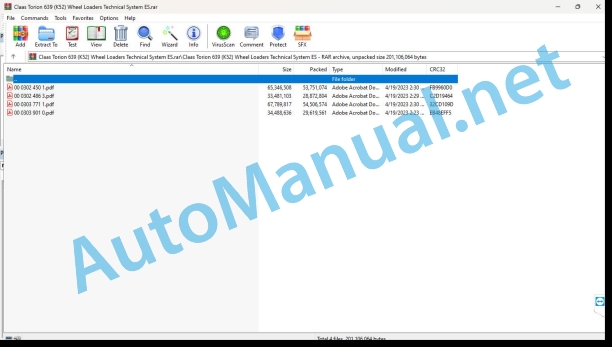
00 0302 450 1.pdf
00 0302 486 3.pdf
00 0303 771 1.pdf
00 0303 901 0.pdf
00 0302 450 1.pdf:
TORION 535TORION 639
Introduction
Manual validity
Manual validity
Security
General information
Signage of warning and danger indications
security routines
First aid measures
CCN Explanation
CCN (CLAAS Component Number)
Electrical regulations
Hydraulic regulations
CCN (CLAAS Component Number)
01 Engine
0125 Fuel/injection system
Fuel system
Table of measured values
Function Description
0150 Engine coupled parts
Synopsis of the electrical components of the diesel engine
0155 Engine adjustment
Electronic engine regulation
Table of measured values
Function Description
0165 Exhaust gas aftertreatment
Exhaust gas aftertreatment
0197 Check / measure / adjust
Engine Check Report
Important notices and preparations
Check report
Check and adjust the drive
Check the speed of the diesel engine
Particulate filter service regeneration
03 Chassis
0335 Propulsion
Hydraulic propulsion system
Function Description
propulsion pump
Table of measured values
Function Description
propulsion motor
Function Description
0397 Check / measure / adjust
Propulsion check report
Important notices and preparations
Check report
Check and adjust propulsion
Check and adjust the propulsion pump
Check and adjust the propulsion motor
04 Brake
0400 Brake
Table of measured values
Function Description
0497 Check / measure / adjust
Brake System Check Report
Important notices and preparations
Check report
Check and adjust the brake system
Check and adjust inch valve
05 Address
0505 Address
Function Description
0597 Check / measure / adjust
Check and adjust the steering system
Important notices and preparations
Check the control module
06 Lifting device
0630 Lifting arms
Work equipment
Function Description
0697 Check / measure / adjust
Check report – working hydraulic system
Important notices and preparations
Check report
Check and adjust the working hydraulic system
Check and adjust the control block
Stabilization module
Check the shutdown function
Check the forward vibration damping hydraulic accumulator
09 Hydraulics
0905 Hydraulic oil tank
Oil temperature adjustment
Function Description
0910 Bombs
Working hydraulic system pump
Table of measured values
Function Description
Priority valve
Only active working hydraulic system (a)
Active management team (b)
0920 Valves
Working hydraulic system control block
Function Description
Stabilization module
Function Description
Command module
Function Description
0980 Hydraulic connection diagram
Connection diagram of the working hydraulic system
Hydraulic working system with 3. manual function
Working hydraulic system with 3rd and 4th electrical function
Connection diagram of the hydraulic propulsion system
Wiring diagram of the steering hydraulic system
0997 Check / measure / adjust
Check the nitrogen filling of the hydraulic accumulator
10 Install. electrical/electronic
1012 Modules / sensors
A10-LBH module – display
Denominations
Denominations
1030 On-board computer / display devices
Adjust service hours on the screen
1080 Electrical connection diagram
Connection diagrams of the electrical installation of the machine (SCM), emissions phase 3B
SCM 11 – Power supply
Denominations
SCM 12 – Load control, buzzer
Denominations
SCM 13 – Control lever, forward direction, reverse gear warning device
Denominations
SCM 14 – Advance pedal
Denominations
SCM 15 – Fuel level, gear ranges
Denominations
SCM 16 – Flashing Light System
Denominations
SCM 17 – Windshield wipers, horn
Denominations
SCM 18 – Work lights, interior lighting
Denominations
SCM 19 – Advance Light
Denominations
SCM 20 – Dirty air filter, display illumination
Denominations
SCM 21 – Display power, hydraulic oil temperature
Denominations
SCM 22 – Control lever power, working hydraulic system lock
Denominations
SCM 23 – Radio, operator’s seat, 12 V socket
Denominations
SCM 24 – Rotating flashing light, rear windshield heating
Denominations
SCM 25 – Heating and air conditioning equipment (machine side)
Denominations
SCM 26 – Heating and air conditioning equipment (system side)
SCM 27 – Quick Changer, Feed Direction Control Feed
Denominations
SCM 29 – Diesel particulate filter regeneration
Denominations
SCM 31 – Relay/fuse reserve
Denominations
SCM 32 – 3. control circuit I
Denominations
SCM 33 – 3. control circuit II
Denominations
SCM 36 – Starter, generator, preheating system, exhaust gas recirculation
Denominations
SCM 37 – Diesel particulate filter check
Denominations
SCM 38 – Engine oil pressure, fuel pump, engine diagnosis
Denominations
SCM 39 – X36 Diesel Engine Transfer Connector
Denominations
SCM 40 – X37 Diesel Engine Transfer Connector
Denominations
SCM 41 – X38 Diesel Engine Transfer Connector
Denominations
SCM 42 – X39 Diesel Engine Transfer Connector
Denominations
SCM 43 – Power supply / motor ground
Denominations
SCM 46 – Mirror heating option
Denominations
SCM 47 – Option warning device for reverse gear (acoustic)
Denominations
SCM 48 – Regulated transported quantity option
Denominations
SCM 49 – Trailer hitch option
Denominations
SCM 50 – Strobe Option
Denominations
SCM 51 – Contour light option, sweeper option
Denominations
SCM 52 – Central lubrication system, anti-break tube protection
Denominations
SCM 53 – 4th control circuit
Denominations
SCM 54 – Automatic engine stop option
Denominations
SCM 56 – Vibration damping option during advancement
Denominations
SCM 59 – OBD Diagnostic Connector and Telemetry System
Denominations
1085 Networks
Function Description
12 Driver’s cab/platform
1240 Air conditioning equipment
Heating, ventilation, air conditioning installation
Function Description
75 Central lubrication
7505 Container, pump
Central lubrication system
Function Description
7515 Lubrication/piping equipment
Fat distribution
92 Diagnosis
9210 Machine Error Codes
Error codes
Location of components
Hydraulic installation
1001-1999 Oil tank/filter/radiator
2001-2999 Pump/motor
3001-3999 Hydraulic Cylinder
5001-5999 Pressure accumulator
6001-6999 Valves – mechanically actuated (hydraulic installation)
7001-7999 Valves – hydraulically actuated
8001-8999 Couplings/connections
9001-9999 Measuring points / indicating instruments
Electrical installation
To Terminal/modules
B Sensors
H Device – / signal light
K Relays
M Engine
R Potentiometers/resistors
S Switch/button – cabin operation
X Pluggable connections
and electromagnetic coils
00 0303 771 1.pdf:
TORION 535TORION 639
Introduction
Information regarding the instruction manual
Manual validity
Information regarding this technical systems manual
Using the manual
Structuring with construction group structure
Search and find
Direction signs
Security
Recognize warning signs
Danger symbols
Safety instructions
Graphic danger symbols and warning indications
Requirements for technical personnel
Children in danger
Machine danger zones
Accompanying instructor during work
Risk of injury due to rotating shafts
Construction modifications to the machine
Optional equipment and spare parts
Control of the machine running
Technical status
Comply with technical limit values
Danger from machine parts during coasting
Keep protective devices operational
Personal protective equipment
Wear appropriate clothing
Remove dirt and loose objects
Park the machine safely
Unsuitable consumables
Safe handling of consumables and auxiliary materials
Environmental protection and waste disposal
Keep the cabin free of chemicals
Fire prevention
Lethal electrical shock due to overhead power lines and lightning strikes
Current discharge through the electrical installation
Noise can cause health damage
Prestressed machine parts
Liquids under pressure
Air under presure
Toxic exhaust gases
Hot surfaces
Safe ascent and descent
Only work on the stopped machine
Dangers in repair work
Machine parts and lifted loads
Danger from welding work
Check and charge the battery
Emergency Preparations
CCN Explanation
CCN (CLAAS Component Number)
Electrical regulations
Hydraulic regulations
CCN (CLAAS Component Number)
01 Engine
0125 Fuel/injection system
Fuel system
Table of measured values
Function Description
0150 Engine coupled parts
Synopsis of the electrical components of the diesel engine
0155 Engine adjustment
Electronic engine regulation
Table of measured values
Function Description
0165 Exhaust gas aftertreatment
Exhaust gas aftertreatment
0197 Check / measure / adjust
Engine Check Report
Important notices and preparations
Check report
Check and adjust the drive
Check the speed of the diesel engine
Particulate filter service regeneration
03 Chassis
0335 Propulsion
Propulsion
Table of measured values
Function Description
propulsion pump
Table of measured values
Function Description
propulsion motor
Function Description
0397 Check / measure / adjust
Propulsion check report
Important notices and preparations
Check report
Check and adjust propulsion
Check and adjust the propulsion pump
Check and adjust the propulsion motor
04 Brake
0400 Brake
Table of measured values
Function Description
0497 Check / measure / adjust
Brake System Check Report
Important notices and preparations
Check report
Check and adjust the brake system
Check and adjust inch valve
05 Address
0505 Address
Function Description
0597 Check / measure / adjust
Check and adjust the steering system
Important notices and preparations
Check the control module
06 Lifting device
0630 Lifting arms
Work equipment
Function Description
0697 Check / measure / adjust
Check report – working hydraulic system
Important notices and preparations
Check report
Check and adjust the working hydraulic installation
Check and adjust the control block
Stabilization module
Check the shutdown function
Check the forward vibration damping hydraulic accumulator
09 Hydraulics
0905 Hydraulic oil tank
Oil temperature adjustment
Function Description
0910 Bombs
Hydraulic system pump working up to K5000260, K5200209
Table of measured values
Function Description
Priority valve
Only the working hydraulic system is active (a)
Active management team (b)
Hydraulic system pump working from K5000261, K5200210
Function Description
Priority valve
Only the working hydraulic system is active (a)
Active management team (b)
0920 Valves
Working hydraulic system control block
Function Description
Stabilization module
Function Description
Command module
Function Description
0980 Hydraulic connection diagram
Connection diagram of the working hydraulic system
Hydraulic working system with 3. manual function
Working hydraulic system with 3rd and 4th electrical function
Connection diagram of the hydraulic propulsion system
Wiring diagram of the steering hydraulic system
0997 Check / measure / adjust
Check the nitrogen filling of the hydraulic accumulator
10 Install. electrical/electronic
1012 Modules / sensors
A10-LBH module – display
Denominations
Denominations
A200-LBH module – central control
Denominations
Denominations
1030 On-board computer / display devices
Adjust service hours on the screen
1080 Electrical connection diagram
Connection diagrams for the electrical installation of the machine (SCM), emissions level 5
SCM 12 – Voltage supply
Denominations
SCM 13 – Load control, buzzer
Denominations
SCM 14 – Forward direction, reverse warning device
Denominations
SCM 15 – Control lever
Denominations
SCM 16 – Advance pedal
Denominations
SCM 17 – Fuel level, gear ranges
Denominations
SCM 18 – Flashing Light System
Denominations
SCM 19 – Windshield wipers, horn
Denominations
SCM 20 – Work lights, interior lighting
Denominations
SCM 21 – Advance Light
Denominations
SCM 22 – Dirty air filter, display illumination
Denominations
SCM 23 – Display power, CAN, hydraulic oil temperature
Denominations
SCM 24 – Control lever supply, work hydraulic system lock
Denominations
SCM 25 – Radio, operator’s seat, 12 V socket
Denominations
SCM 26 – Rotating flashing light, rear windshield heating
Denominations
SCM 27 – Heating and air conditioning installation (on the machine)
Denominations
SCM 28 – Heating and air conditioning installation (on site)
SCM 29 – Quick changer
Denominations
SCM 30 – Parking brake
Denominations
SCM 31 – Diesel particulate filter regeneration
Denominations
SCM 33 – Relay/fuse reserve
Denominations
SCM 34 – Release 3. / 4. control circuit
Denominations
SCM 35 – 3. control circuit I
Denominations
SCM 36 – 3. control circuit II
Denominations
SCM 38 – Activation of options
Denominations
SCM 39 – Central control power supply
Denominations
SCM 42 – Starter, generator, preheating system, exhaust gas return
Denominations
SCM 43 – Diesel particulate filter check
Denominations
SCM 44 – Engine oil pressure, fuel pump, engine diagnosis
Denominations
SCM 45 – X36 Diesel Engine Transfer Connector
Denominations
SCM 46 – X37 Diesel Engine Transfer Connector
Denominations
SCM 47 – X38 Diesel Engine Transfer Connector
Denominations
SCM 48 – X39 Diesel Engine Transfer Connector
Denominations
SCM 49 – Motor power / ground
Denominations
SCM 52 – Mirror heating option
Denominations
SCM 53 – Option warning device for reverse gear (acoustic)
Denominations
SCM 54 – Regulated transported quantity option
Denominations
SCM 55 – Trailer hitch option
Denominations
SCM 56 – Strobe Option
Denominations
SCM 57 – Contour light option, sweeper option
Denominations
SCM 58 – Central lubrication system, pipe breakage protection, operator’s cabin fan
Denominations
SCM 59 – 4. control circuit
Denominations
SCM 60 – Automatic engine stop option
Denominations
SCM 62 – Vibration damping option during travel
Denominations
SCM 63 – Manual slow speed device angle sensor option
Denominations
SCM 66 – OBD Diagnostic Connector and Telemetry System
Denominations
1085 Networks
Function Description
12 Driver’s cab/platform
1240 Air conditioning equipment
Heating, ventilation, air conditioning installation
Function Description
75 Central lubrication
7505 Container, pump
Central lubrication system
Function Description
7515 Lubrication/piping equipment
Fat distribution
92 Diagnosis
9210 Machine Error Codes
Error codes
Location of components
Hydraulic installation
1001-1999 Oil tank/filter/radiator
2001-2999 Pump/motor
3001-3999 Hydraulic Cylinder
5001-5999 Pressure accumulator
6001-6999 Valves – mechanically actuated (hydraulic installation)
7001-7999 Valves – hydraulically actuated
8001-8999 Couplings/connections
9001-9999 Measuring points / indicating instruments
Electrical installation
To Terminal/modules
B Sensors
H Device – / signal light
K Relays
M Engine
R Potentiometers/resistors
S Switch/button – cabin operation
X Pluggable connections
and electromagnetic coils
John Deere Repair Technical Manual PDF
John Deere Transmission Control Unit Component Technical Manual CTM157 15JUL05
John Deere Repair Technical Manual PDF
John Deere Repair Technical Manual PDF
John Deere Repair Technical Manual PDF
John Deere Repair Technical Manual PDF
John Deere DF Series 150 and 250 Transmissions (ANALOG) Component Technical Manual CTM147 05JUN98
John Deere Repair Technical Manual PDF
John Deere Repair Technical Manual PDF
John Deere Repair Technical Manual PDF
John Deere Repair Technical Manual PDF

