Claas Torion 956 Sinus (K54) Wheel Loaders Repair Manual EN
$100.00
- Model: Torion 956 Sinus (K54) Wheel Loaders
- Type Of Manual: Repair Manual
- Language: EN
- Format: PDF(s)
- Size: 125 MB
File List:
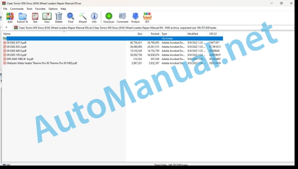
00 0302 837 0.pdf
00 0302 853 2.pdf
00 0303 840 0.pdf
00 0305 185 0.pdf
DPS 4045 TIER 4f 4i.pdf
Webasto Water heater Thermo Pro 90 Thermo Pro 90 HDD.pdf
00 0302 837 0.pdf:
INTRODUCTION
VERSION TRACKING
MANUAL APPLICABILITY AND SUPPORTED MODELS
SPECIFICATIONS
DATA PLATE
CONVERSION TABLES
Units of pressure
Unit of weight
Units of torque
TORQUE SPECIFICATIONS
COARSE PITCH
FINE PITCH
WHEEL NUT TIGHTENING TORQUES
MAINTENANCE
MAINTENANCE POINTS
Integrated reduction gear
FLANGED reduction gear
OIL DRAINING MANDATORY PROCEDURE
MAINTENANCE INTERVALS
LUBRICANT & SEALANT SPECIFICATIONS
SAFETY PRECAUTIONS
Hydraulic gear control
Exploded view
Disassembly
Assembly
2nd GEAR SWITCH ADJUSTMENT
1st GEAR SWITCH ADJUSTMENT
Hydraulic gear control – valve on board
Exploded view
Disassembly
Assembly
Hydraulic gear control (contactless sensor)
Exploded view
Disassembly
Assembly
Sensor functionality check
Counter-revolution sensor
Replacement
SHORT FLANGED REDUCTION GEAR
Exploded view
Disassembly
INPUT SHAFT
Assembly
Gearbox installation
Disassembly
Integrated gear box
Exploded view
Disassembly
Assembly
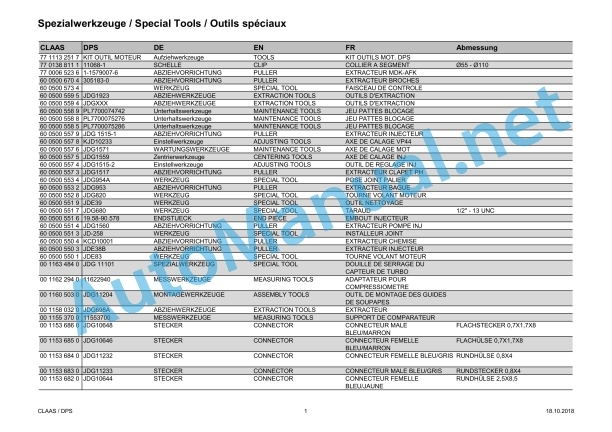
SPECIAL TOOLS
SPECIAL TOOLS
00 0302 853 2.pdf:
TORION 956 SINUS
Table of contents
Introduction
General information
Validity of manual
Using the manual
Text and figures
Document structure based on sub-assemblies
Search and find
Directions
Abbreviations
Technical terms
General repair instructions
Technical specifications
Information on technically correct repairs
Self-locking bolts
Liquid locking compound
Steel roller chains
Tensioning
Chain connector
Chain connector type E with spring
Chain connector type G with wire
Chain connector type S with cotter pins
Taper ring fasteners
Dismounting
Installing
Gib head key connections
Dismounting
Installing
Lock collar bearing
Dismounting
Installing
Adapter sleeve bearing
Dismounting
Installing
Chuck bushing
Removing
Dismounting of version A
Dismounting of version B
Installing
Chuck bushing version A
Chuck bushing version B
Circlips
Ferrule fittings
Screwing in
Leaky ferrule fittings
Sealing cone fittings
Hydraulic hoses
Hose placement
Treatment of sealing faces
Spare parts
Operating materials
Tightening torques
Tightening torques for metric standard and fine threads
Tightening torques for hydraulic fittings with ferrule
Tightening torques for screwed pipe connections with sealing cone joint and hydraulic threaded joints with soft core seal
Tightening torques for hydraulic male connectors SDS shape B and E
Tightening torques for hydraulic swivel screw fittings
Tightening torque for hollow screws (with copper sealing ring)
Tightening torques for hydraulic male connectors SDE shape H, with adjustable direction
Tightening torques for brake line screw fittings
Tightening torque for tubes with O-ring and union nuts
Tightening torques for worm drive hose clamps
Tightening torques for hose clamps with round pins
General tightening torques for Bosch-Rexroth
CCN explanation
CCN (CLAAS Component Number)
Electric systems standard
Hydraulic system standard
CCN (CLAAS Component Number)
General information
Safety and hazard information
Important
Signal word
General safety and accident prevention regulations
First-aid measures
Danger of injury from hydraulic liquid
Leaving the machine
Putting the machine out of operation
Jacking up the machine
Adjusting and maintenance work
Welding work
01 Engine
0102 Complete component
Diesel engine
Technical specifications
Work preparation
Removing
Installing
0125 Injection / Fuel system
Fuel tank
Technical specifications
Removing
Installing
Fuel sediment filter
Technical specifications
Removing
Installing
Fuel cooler
Technical specifications
Removing
Installing
0130 Lubricating oil system
Oil filter
Technical specifications
Removing
Installing
0135 Cooling system
Engine radiator
Technical specifications
Work preparation
Removing
Installing
Fan motor
Technical specifications
Removing
Installing
Gear pump
Work preparation
Removing
Installing
0140 Exhaust system
Diesel particulate filter
Technical specifications
Work preparation
Removing
Installing
Exhaust pipe
Technical specifications
0145 Air intake
Air filter housing
Technical specifications
Removing
Installing
Charge air cooler
0165 Exhaust gas aftertreatment
Exhaust gas treatment – General
Work preparation
Special tool
Checking the purity of the urea solution
Checking the density of the urea solution
SCR catalytic converter
Technical specifications
Removing
Installing
Urea tank
Technical specifications
Removing
Installing
Dosing unit
Technical specifications
Removing
Installing
Urea injection nozzle
Technical specifications
Removing
Installing
Urea pre-filter
Technical specifications
Removing
Installing
02 Gearbox / Clutch / Universal drive shaft
0260 Universal drive shaft
Universal drive shaft
Technical specifications
Removing
Disassembling
Assembling
Installing
03 Chassis
0316 Drive axle, front
Front drive axle
Technical specifications
Removing
Installing
Wheel hub
Technical specifications
Auxiliary tools
Removing
Installing
Axle body
Technical specifications
Removing
Installing
Bevel gear drive
Technical specifications
Work preparation
Auxiliary tools
Removing
Installing
Differential
Technical specifications
Work preparation
Auxiliary tools
Removing
Disassembling
Assembling
Installing
0330 Rear steering drive axle
Rear driven steering axle
Technical specifications
Work preparation
Removing
Installing
Stub axle
Technical specifications
Auxiliary tools
Removing
Installing
Wheel hub
Technical specifications
Work preparation
Auxiliary tools
Removing
Installing
Axle body
Technical specifications
Removing
Installing
Floating axle
Technical specifications
Work preparation
Auxiliary tools
Removing
Installing
Bevel gear drive
Technical specifications
Work preparation
Auxiliary tools
Removing
Installing
Differential
Technical specifications
Work preparation
Auxiliary tools
Removing
Disassembling
Assembling
Installing
Axle transfer gearbox
Technical specifications
Work preparation
Removing
Disassembling
Assembling
Installing
Shift cylinder
Technical specifications
Work preparation
Removing
Installing
0335 Ground drive
Ground drive hydraulic motor
Technical specifications
Work preparation
Removing
Installing
0340 Front wheels
Front wheels
Special tool
Removing
Installing
0345 Rear wheels
Rear wheels
Special tool
Removing
Installing
04 Brake
0400 Brake
Technical specifications
Work preparation
Removing
Installing
Service brake 2nd circuit
Technical specifications
Work preparation
Auxiliary tools
Removing
Installing
Brake pedal
Technical specifications
Removing
Installing
Brake oil compensating tank
Removing
Installing
05 Steering
0505 Steering
Steering column
Technical specifications
Removing
Disassembling
Assembling
Installing
Orbitrol
Technical specifications
Removing
Installing
Steering hydraulic cylinder
Technical specifications
Removing
Installing
0530 Articulated steering
Steering linkage
Technical specifications
Work preparation
Removing the left steering rod
Removing the right steering rod
Installing the left steering rod
Installing the right steering rod
Adjusting the track
06 Lift device
0630 Lift arms
Lift arms
Technical specifications
Quick-hitch plate
Technical specifications
Removing
Installing
Lift cylinder
Technical specifications
Removing
Installing
Tipping cylinder
Technical specifications
Removing
Installing
Guide lever
Technical specifications
Removing
Installing
Link plate
Technical specifications
Removing
Installing
09 Hydraulic system
0900 Hydraulic system – General
Hydraulic system – General
Special tool
Filling the accumulator
0905 Hydraulic oil tank
Hydraulic oil tank
Specifications
Special tool
Removing
Installing
Generating a vacuum
Stopping generating a vacuum
0907 Hydraulic oil cooler
Hydraulic oil cooler
0910 Pumps
Ground drive hydraulic pump
Technical specifications
Work preparation
Removing
Installing
Working hydraulics pump
Technical specifications
Work preparation
Removing
Installing
0915 Hydraulic lines
Pilot control hydraulic accumulator
Technical specifications
Removing
Installing
0920 Valves
Pilot control unit
Technical specifications
Removing
Installing
Working hydraulics valve block
Technical specifications
Removing
Installing
Vibration damper valve block
Removing
Installing
Pipe rupture valve
Removing
Installing
10 Electrical / Electronic equipment
1005 Power supply
Technical specifications
Removing
Installing
1010 Central electrics
Central terminal compartment
Technical specifications
Removing
Installing
1012 Modules / sensors
Rear compartment monitoring
Technical specifications
Removing
Installing
1020 Driving lights
Front drive lights
Technical specifications
Removing
Installing
Rear road lighting
Technical specifications
Removing
Installing
Numberplate lighting
Technical specifications
Removing
Installing
Warning beacon
Technical specifications
Removing
Installing
1025 Working lights
Work light
Technical specifications
Removing, front
Removing, rear
Installing, front
Installing, rear
1035 Operation / Multifunction control lever
Technical specifications
Removing
Installing
Control panel 1
Technical specifications
Removing
Installing
Control panel 2
Technical specifications
Removing
Installing
12 Cab / Operator’s platform
1210 Cab
Technical specifications
Removing
Installing
Roof covering
Technical specifications
Removing
Installing
Door lock / locking device
Technical specifications
Work preparation
Removing
Installing
Windscreen washer liquid tank
Technical specifications
Removing
Installing
Front windscreen wiper
Technical specifications
Removing
Installing
Rear wiper
Technical specifications
Removing
Installing
1230 Seat
Driver_x0019_s seat
Technical specifications
Removing
Installing
1235 Cab heater
Heating/cooling housing
Technical specifications
Removing
Installing
1240 Air condition
Air conditioner condenser
Technical specifications
Removing
Installing
Air conditioner compressor
Technical specifications
Removing
Installing
75 Central lubrication system
7505 Reservoir / Pump
Grease container
Technical specifications
Removing
Installing
7510 Distributor
Progressive distributor
Removing the main progressive distributor
Removing the rear section progressive distributor
Removing the front section progressive distributor
Removing the lift arms progressive distributor
Installing the lift arms progressive distributor
Installing the front section progressive distributor
Installing the rear section progressive distributor
Installing the main progressive distributor
80 Various components / Machine body
8015 Access
Cab access
Technical specifications
Removing
Installing
8025 Panellings / Hoods
Engine bonnet
Technical specifications
Removing
Installing
Side panel
Technical specifications
Removing the right side panel
Installing the right side panel
Removing the cooling system side panel
Installing the cooling system side panel
Inspection cover
Removing the inspection cover
Installing the inspection cover
8030 Mud guards
Wheel case
Remove the rear left wheel case.
Installing the rear left wheel case
Remove the rear right wheel case
Install the rear right wheel case
8045 Legal equipment
Backup warning unit
Removing
Installing
95 Maintenance parts overview
9599 Maintenance jobs
Maintenance position 1
Maintenance position 2
Adjusting the valve lash
Checking the glow plugs of the diesel engine
Changing the diesel engine oil
Draining oil
Topping up oil
Changing the diesel engine oil filter
Work preparation
Replacing the filter element of the diesel engine oil separator
Changing the fuel pre-filter
Changing the fuel fine filter element
Bleeding the fuel system
Checking the ventilation system of the crankcase
Checking the anti-freeze and anti-rust protection function of the diesel engine coolant
Correcting the anti-freeze concentration
Use of anti-rust compound without anti-freeze
Changing the coolant
Draining the coolant
Topping up coolant
Top up coolant in the cooling system
Topping up coolant in the compensating tanks
Checking the diesel engine belt
Changing the diesel engine belt
Checking the intake system and the exhaust system
Checking the intake system
Checking the exhaust system
Changing the filter module of the diesel particulate filter
Changing the urea filter
Changing the urea pre-filter element
Checking the axle transfer gearbox oil level
Changing the axle transfer gearbox oil
Draining oil
Topping up oil
Testing and measuring the ground drive
Checking the universal drive shafts
Checking the axles’ oil level
Differential gear
Wheel hubs
Changing the axles’ oil
Draining the differential gearbox oil
Topping up the differential gearbox oil
Draining the wheel hubs’ oil
Topping up the wheel hubs’ oil
Checking the tightening torque of the mounting bolts on the axles
Greasing the steering knuckle bearings
Greasing the steering knuckle bearings
Checking the wear of brake discs
Work preparation
Checking the operating clearance and the wear of service brake 2nd circuit
Checking the wear
Checking the operating clearance
Testing and measuring the brake system
Testing and measuring the steering system
Checking the bearing seat of steering knuckle bearings and conical joints of steering rods
Checking the bearing seat
Checking the bucket bearing sleeves on the lift arms
Checking the bucket stops
Draining the condensate and sediment from the hydraulic oil tank
Changing the hydraulic oil tank return line filter cartridge
Changing the hydraulic oil tank fresh air filter element
Changing the hydraulic oil
Draining the hydraulic oil
Topping up hydraulic oil
Performing a hydraulic oil analysis
Cleaning and lubricating the pilot control unit
Checking and measuring the working hydraulics
Checking the liquid level of batteries
Replacing the forward/reverse control rocker switch and the multifunction handle cap
Checking the air conditioner filter receiver dryer
Checking the heater and air conditioning system
00 0303 840 0.pdf:
TORION 537TORION 644TORION 956
Table of contents
Validity of manual
Validity of manual
General safety precautions
Important
Marking of warnings and hazard prevention notes
10 Electrical / Electronic equipment
1000 Electrical / Electronic equipment general
Shipping package of repair kit 00 1954 769 X
Installation of repair kit 00 1954 769 X – machine types K51 and K53
Installation of repair kit 00 1954 769 X – machine type K54
00 0305 185 0.pdf:
DPS 4045DPS 6068
Table of contents
Introduction
General information
Validity of manual
Using the manual
Text and figures
Document structure based on sub-assemblies
Search and find
Directions
Abbreviations
Technical terms
General repair instructions
Technical specifications
Information on technically correct repairs
Self-locking bolts
Liquid locking compound
Steel roller chains
Tensioning
Chain connector
Chain connector type E with spring
Chain connector type G with wire
Chain connector type S with cotter pins
Taper ring fasteners
Dismounting
Installation
Gib head key connections
Dismounting
Installation
Lock collar bearing
Dismounting
Installing
Adapter sleeve bearing
Dismounting
Installation
Chuck bushing
Removing
Dismounting of version A
Dismounting of version B
Installing
Chuck bushing version A
Chuck bushing version B
Circlips
Ferrule fittings
Screwing in
Leaky ferrule fittings
Sealing cone fittings
Hydraulic hoses
Hose placement
Treatment of sealing faces
Spare parts
Tightening torques
Tightening torques for metric ISO screw thread
Tightening torques for metric fine thread
Tightening torques for screwed pipe connections with sealing cone joint and hydraulic threaded joints with soft core seal
Tightening torques for hydraulic fittings with ferrule
Tightening torques for hydraulic male connectors SDS shape B and E
Tightening torques for hydraulic swivel screw fittings
Tightening torque for hollow screws (with copper sealing ring)
Tightening torques for hydraulic male connectors SDE shape H, with adjustable direction
Tightening torques for brake line screw fittings
Tightening torques for worm drive hose clamps
Tightening torques for hose clamps with round pins
CCN explanation
CCN (CLAAS Component Number)
Electric systems standard
Hydraulic system standard
CCN (CLAAS Component Number)
Explanation of symbols
Personnel requirements
Follow the safety instructions
Proposition 65 (California)
Rules for avoiding damage to health and personal injury
Rules and regulations on pollutant emissions
Fuels, lubricants and coolant
01 Engine
0102 Complete component
Cranking the engine
Special tool
0110 Engine housing
Timing gear cover
Technical specifications
Removing
Installing
Timing gear cover
Technical specifications
Removing
Installing
Front panel
Technical specifications
Removing
Installing
Front panel
Technical specifications
Removing
Installing
Cylinder block
Technical specifications
Dimensional properties of the four-cylinder engine
Work preparation
Special tool
Removing
Checking
Installing
Cylinder block
Technical specifications
Special tool
Removing
Checking
Installing
Oil sump
Technical specifications
Removing
Installing
Oil sump
Technical specifications
Removing
Installing
Exhaust gas throttle valve (twin turbochargers)
Technical specifications
Removing
Installing
Crankcase ventilation
Technical specifications
Checking
Crankcase ventilation
Technical specifications
Removing
Checking
Installing
Crankshaft front seal
Technical specifications
Special tool
Removing
Installing
Crankshaft front seal
Technical specifications
Special tool
Removing
Installing
Crankshaft rear seal
Technical specifications
Special tool
Removing
Installing
Crankshaft rear seal
Technical specifications
Special tool
Removing
Installing
Flywheel housing
Technical specifications
Removing
Checking
Installing
Flywheel housing
Technical specifications
Removing
Checking
Installing
0115 Engine unit
Piston with connecting rod
Technical specifications
Special tool
Removing
Disassembling
Checking
Assembling
Installing
Measuring the excess dimension
Piston with connecting rod
Technical specifications
Special tool
Removing
Disassembling
Checking
Assembling
Installing
Measuring the excess dimension
Cylinder liner
Technical specifications
Special tool
Removing
Installing
Checking
Check the excess length
Cylinder liner
Technical specifications
Special tool
Removing
Installing
Checking
Check the excess length
Crankshaft
Technical specifications
Special tool
Removing
Checking
Checking the oil clearance
Checking the axial play
Reconditioning
Installing
Removing the crankshaft gear
Installing the crankshaft gear
Removing the crankshaft timing wheel
Installing the crankshaft timing wheel
Crankshaft
Technical specifications
Special tool
Removing
Checking
Checking the oil clearance
Checking the axial play
Reconditioning
Installing
Removing the crankshaft gear
Installing the crankshaft gear
Removing the crankshaft timing wheel
Installing the crankshaft timing wheel
Oscillation damper
Technical specifications
Special tool
Removing
Checking
Installing
Flywheel
Technical specifications
Removing
Disassembling
Assembling
Checking
Installing
Flywheel
Technical specifications
Removing
Disassembling
Assembling
Checking
Installing
Gear wheels of the valve train
Technical specifications of the four-cylinder engine
Dimensional properties
Special tool
Removing the upper intermediate gear wheel
Installing the upper intermediate gear wheel
Removing the lower intermediate gear wheel
Installing the lower intermediate gear wheel
Axial play of the intermediate gear wheels
Checking the upper intermediate gear wheel
Checking the lower intermediate gear wheel
Checking the backlash of the gear wheels of the valve train
Six-cylinder engine
Gear wheels of the valve train
Technical specifications of the six-cylinder engine
Dimensional properties
Special tool
Removing the upper intermediate gear wheel
Installing the upper intermediate gear wheel
Removing the lower intermediate gear wheel
Installing the lower intermediate gear wheel
Axial play of the intermediate gear wheels
Checking the upper intermediate gear wheel
Checking the lower intermediate gear wheel
Checking the backlash of the gear wheels of the valve train
Six-cylinder engine
Piston spray nozzle
Technical specifications
Removing
Checking
Installing
Piston spray nozzle
Technical specifications
Removing
Checking
Installing
Equaliser shafts
Specifications
Dimensional properties
Work preparation
Special tool
Removal Procedure
Removing the bushes
Checks and measurements
Bushings
Bore holes for the bushes
Main bearing of the equaliser shaft
Stop plate
Installing the bushes
Exchanging the equaliser shaft gear wheel
Installation
Checking the axial play of the equaliser shaft
Adjusting the equaliser shaft and the lower intermediate gear wheel
0120 Cylinder head / Valves / Idler gear
Valve cover
Technical specifications
Removing
Installing
Valve cover
Technical specifications
Removing
Installing
Checking
Cylinder head
Technical specifications
Special tool
Removing
Installing
Checking
Cylinder head
Technical specifications
Special tool
Removing
Installing
Checking
Glow plugs
Technical specifications
Removing
Installing
Checking
Glow plugs
Technical specifications
Removing
Installing
Checking
Glow plug heat shield
Technical specifications
Glow plug heat shield
Option A
Technical specifications
Removing
Installing
Option B
Technical specifications
Removing
Installing
Glow plug wiring harness
Technical specifications
Removing
Installing
Glow plug wiring harness
Technical specifications
Removing
Installing
Rocker arm
Technical specifications
Work preparation
Removing
Disassembling
Assembling
Installing
Checking the rocker arm
Rocker arm
Technical specifications
Work preparation
Special tool
Removing
Disassembling
Assembling
Installing
Checking the rocker arm
Technical specifications
Special tool
Removing the valves
Removing the valve guide
Removing the valve seat inserts
Installing the valve guide
Installing the valve seat inserts
Installing the valves
Checking the valves
Checking / adjusting the valve clearance
Technical specifications
Special tool
Removing the valves
Removing the valve guide
Removing the valve seat inserts
Installing the valve guide
Installing the valve seat inserts
Installing the valves
Checking the valves
Checking / adjusting the valve clearance
Camshaft
Technical specifications
Special tool
Removing the camshaft
Removing the camshaft gear
Removing the camshaft bush
Installing the camshaft bush
Installing the camshaft gear
Installing the camshaft
Checking
Adjusting the camshaft gear
Camshaft
Technical specifications
Special tool
Removing the camshaft
Removing the camshaft gear
Removing the camshaft bush
Installing the camshaft bush
Installing the camshaft gear
Installing the camshaft
Checking
Adjusting the camshaft gear
Cam tappet
Technical specifications
Removing
Installing
Cam tappet
Technical specifications
Removing
Installing
Checking
0125 Injection / Fuel system
High-pressure pump
Technical specifications
Special tool
Removing
Disassembling
Assembling
Installing
Control valve
Technical specifications
Removing
Installing
High-pressure pump
Specifications
Work preparation
Special tool
Removing
Disassembling
Assembling
Installing
Low-pressure fuel pump (four-cylinder engine)
Technical specifications
Removing
Installing
Pressure relief valve of the fuel common rail
Technical specifications
Removing
Installing
Pressure relief valve
Technical specifications
Removing
Installing
Flow controller
Technical specifications
Special tool
Removing
Installing
Flow controller
Technical specifications
Special tool
Removing
Installing
Technical specifications
Special tool
Removing
Installing
Technical specifications
Special tool
Removing
Installing
Fuel control solenoid coil
Technical specifications
Removing
Installing
Fuel pressure sensor
Technical specifications
Removing
Installing
Injection nozzle wiring harness
Technical specifications
Removing
Installing
Injection nozzle wiring harness
Technical specifications
Removing
Installing
Solenoid coil of the pressure control valve
Technical specifications
Removing
Installing
High-pressure injection lines and supply pipes
Technical specifications
Special tool
Removing
Installing
High-pressure injection lines and supply pipes
Technical specifications
Special tool
Removing
Installing
Injection nozzles
Technical specifications
Special tool
Removing
Installing
Injection nozzles
Technical specifications
Special tool
Removing
Installing
Injection nozzle sleeves
Technical specifications
Work preparation
Special tool
Removing
Installing
Injection nozzle sleeves
Technical specifications
Work preparation
Special tool
Removing
Installing
Push rods of the fuel feed pump
Technical specifications
Removing
Checking
Installing
Fuel leakage line
Technical specifications
Removing
Installing
Line from the high-pressure fuel pump to the common rail
Technical specifications
Removing
Installing
0130 Lubricating oil system
Oil pump
Specifications
Special tool
Removing
Installing
Oil pump
Specifications
Removing the oil pump
Installing the oil pump
Oil cooler adapter plate
Specifications
Removing
Installing
Filter and oil cooler
Technical specifications of the four-cylinder engine
Removing the oil cooler
Removing the oil filter bypass valve
Installing the oil filter bypass valve
Installing the oil cooler
Removing the cover plate of the oil filler adapter
Installing the cover plate of the oil filler adapter
Filter and oil cooler
Technical specifications of the six-cylinder engine
Removing the oil cooler
Removing the oil filter head
Removing the oil filter bypass valve
Installing the oil filter head
Installing the oil filter bypass valve
Installing the oil cooler
Checking
Oil pressure controller
Specifications
Special tool
Removing
Installing
Oil pressure controller
Technical specifications
Special tool
Removing
Installing
Oil intake pipe
Technical specifications
Removing
Installing
Oil supply line of the turbocharger with exhaust gas bypass valve (single turbocharger)
John Deere Repair Technical Manual PDF
John Deere Repair Technical Manual PDF
John Deere Parts Catalog PDF
John Deere Tractors 7500 Parts Catalog CPCQ26568 30 Jan 02 Portuguese
John Deere Parts Catalog PDF
John Deere Tractors 6300, 6500, and 6600 Parts Catalog CQ26564 (29SET05) Portuguese
John Deere Repair Technical Manual PDF
John Deere 18-Speed PST Repair Manual Component Technical Manual CTM168 10DEC07
John Deere Repair Technical Manual PDF
John Deere Repair Technical Manual PDF
John Deere Repair Technical Manual PDF
John Deere Transmission Control Unit Component Technical Manual CTM157 15JUL05

