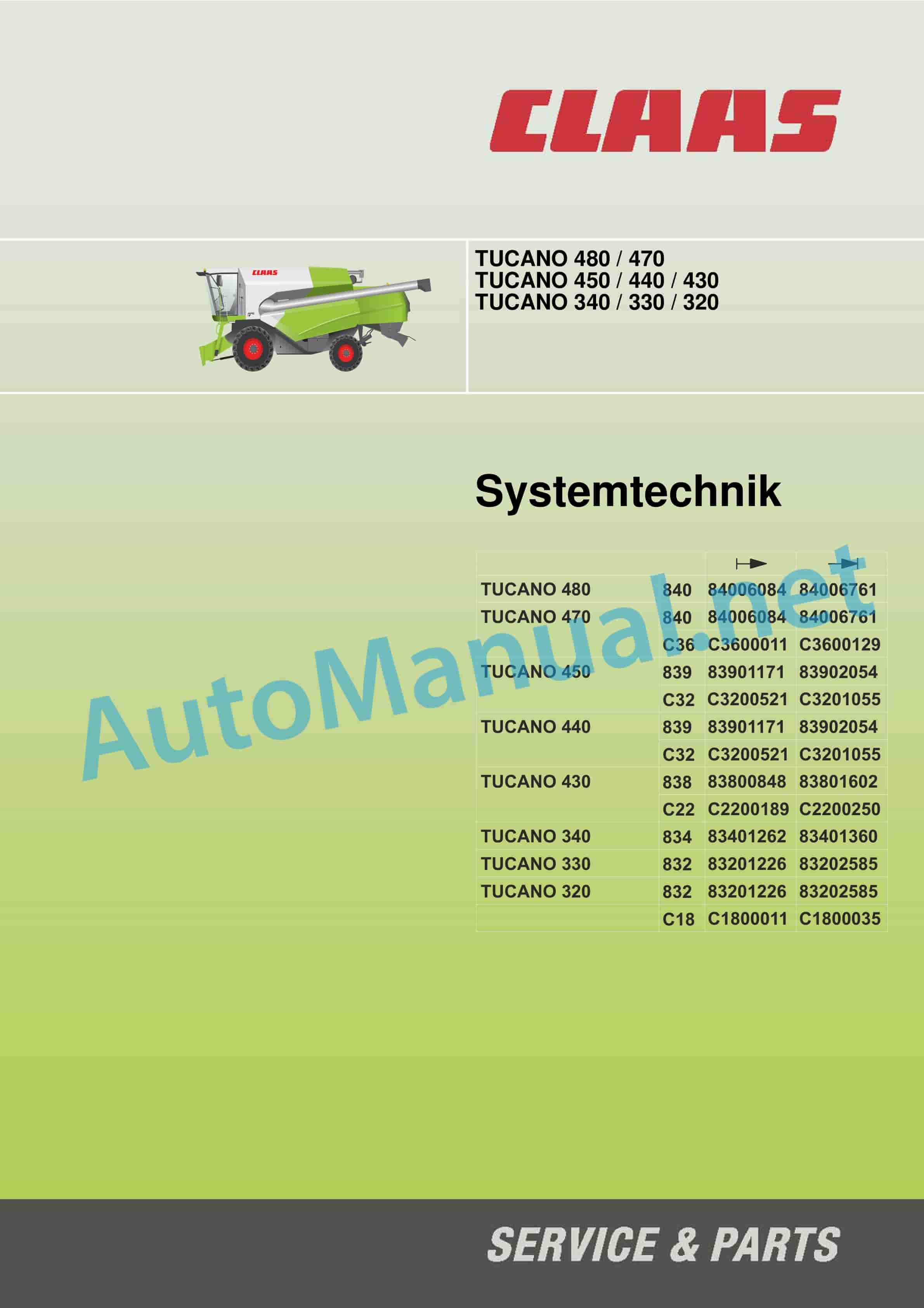
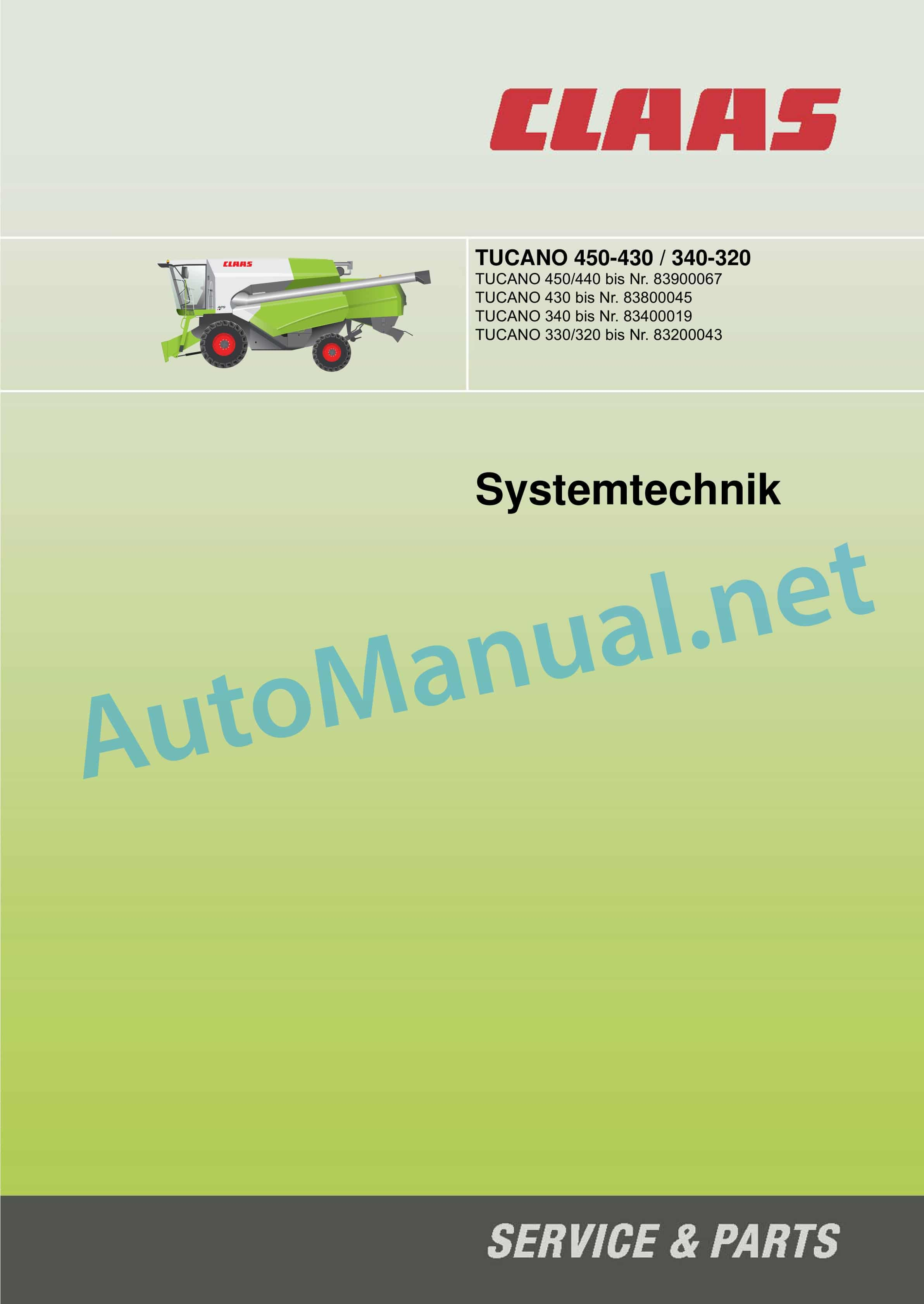
Claas TUCANO 330-320 (832) Combine Technical System DE
$300.00
- Model: TUCANO 330-320 (832) Combine
- Type Of Manual: Technical System
- Language: DE
- Format: PDF(s)
- Size: 216 MB
File List:
– 00 0290 241 0.pdf
– 00 0290 640 1.pdf
– 00 0291 026 2.pdf
– 00 0292 118 1.pdf
– 00 0295 561 3.pdf
00 0290 241 0.pdf
Table of Content:
1 Table of Contents
2 CCN Declaration
2.1 CCN (CLAAS Component Number)
3 CCN (CLAAS Component Number)
3.1 CCN Index
4 Introduction
4.1 General information
5 01 Motor
5.1 0125 Injection/fuel system
5.2 0150 engine attachments
5.3 0155 Motor control
5.4 0165 Exhaust gas aftertreatment
6 03 Chassis
6.1 0330 Rear steering drive axle
6.2 0335 travel drive
7 04 Brake
7.1 0405 Service brake
8 05 Steering
8.1 0505 Steering
8.2 0510 Automatic steering
9 09 Hydraulics
9.1 0920 Valves
9.2 0980 Hydraulic circuit diagrams
10 10 Electrics / Electronics
10.1 1010 Central Electrics
10.2 1012 modules / sensors
10.3 1015 cable sets
10.4 1035 Operation / Multifunction lever
10.5 1040 Yield measurement
10.6 1080 electrical circuit diagrams
10.7 1081 Connector overview
10.8 1085 Networks
11 12 Cab / Driver’s cab
11.1 1230 seat
11.2 1240 Air conditioning
12 20 Good intake
12.1 2002 attachment
12.2 2010 Cutting table
12.3 2015 Haspel
13 26 Floor guide
13.1 2605 Auto-Contour
14 41 Threshing mechanism
14.1 4100 Threshing mechanism
14.2 4120 Threshing drum
15 43 Cleaning
15.1 4320 sieves / sieve box
15.2 4325 Fan
16 60 Goods deposit / Straw deposit
16.1 6010 straw chopper
17 61 Kornbergung
17.1 6120 Grain tank emptying
18 Diagnosis by error codes
18.1 FMI error code (Failure Mode Indicator)
18.2 Error codes machine
18.3 Error codes diesel engine
19 Location of the components
19.1 Hydraulics
19.2 Electrics
00 0290 640 1.pdf
Table of Content:
2 CCN declarations
2.1 CCN (CLAAS Component Number)
3 CCN (CLAAS Component Number)
4 Introduction
4.1 Validity of the instructions
4.2 3D visualizations
4.3 DAIMLER – Start diesel engine, diesel engine monitoring
5 03 Chassis
5.1 Hydrostatic travel drive
5.2 4-Trac
6 05 Steering
6.1 Steering system
6.2 Functional diagram neutral
6.3 Functional diagram, steering-operated
6.4 Check steering system
7 09 Hydraulics
7.1 Valve blocks
7.2 Circuit diagrams vehicle hydraulics
7.3 Circuit diagrams for hydraulic attachment
8 10 Electrics
8.1 Road travel function – field travel circuit
8.2 Seat contact function
8.3 CAN function (Daimler-Benz)
8.4 Function T-Signal
8.5 Central electrics
8.6 Module
8.7 Introduction to circuit diagrams
8.8 Electrical circuit diagrams for the machine (SCM)
8.9 Circuit diagrams for electrical attachments (SCM)
8.10 Connector representation
9 20 Good recording
9.1 Raise/lower attachment
9.2 Attachment on/off
9.3 Reverse intent
9.4 Raise/lower reel, automatic reel height
9.5 Reel forward/back
9.6 Reel speed adjustment, automatic reel speed control
9.7 VARIO – cutting table adjustment
9.8 Manual lateral control
9.9 Attachment
10 26 Floor guide
10.1 Auto Contour (CAC) / Contour
11 41 Threshing mechanism
11.1 Coupling the threshing mechanism
11.2 Threshing drum speed adjustment
12 43 Cleaning
12.1 Fan speed adjustment
12.2 Sieve adjustment – upper sieve
12.3 Sieve adjustment – lower sieve
13 61 Kornbergung
13.1 Swivel grain tank pipe
13.2 Grain tank emptying
14 Diagnosis according to error codes
14.1 FMI error code (Failure Mode Indicator)
15 Location of components
15.1 Hydraulics
15.2 Electrics
00 0291 026 2.pdf
Table of Content:
1MB OM460LAMB OM502LAMB OM906LAMB OM926LA
2 Table of Contents
3 CCN Declaration
3.1 CCN (CLAAS Component Number)
4 CCN (CLAAS Component Number)
5 Introduction
5.1 Safety instructions
5.2 Validity of the instructions
6 01 Motor
6.1 0125 injection/fuel system
6.2 0155 Motor control
6.3 0165 Exhaust gas aftertreatment
7 10 Electrics / Electronics
7.1 1012 modules / sensors
7.2 1085 Networks
8 92 Diagnosis
8.1 Diagnosis according to error codes
8.2 9220 Error Codes Diesel Engine (J1939)
00 0292 118 1.pdf
Table of Content:
1 Table of Contents
2 CCN Declaration
2.1 CCN (CLAAS Component Number)
3 CCN (CLAAS Component Number)
3.1 CCN Index
4 Introduction
4.1 General information
5 01 Motor
5.1 0125 Injection/fuel system
5.2 0150 engine attachments
5.3 0155 Motor control
5.4 0165 Exhaust gas aftertreatment
6 03 Chassis
6.1 0330 Rear steering drive axle
6.2 0335 travel drive
7 04 Brake
7.1 0405 Service brake
8 05 Steering
8.1 0505 Steering
8.2 0510 Automatic steering
9 09 Hydraulics
9.1 0920 Valves
9.2 0980 Hydraulic circuit diagrams
10 10 Electrics / Electronics
10.1 1010 Central Electrics
10.2 1012 modules / sensors
10.3 1015 cable sets
10.4 1035 Operation / Multifunction lever
10.5 1040 Yield measurement
10.6 1080 electrical circuit diagrams
10.7 1081 Connector overview
10.8 1085 Networks
11 12 Cab / Driver’s cab
11.1 1230 seat
11.2 1240 Air conditioning
12 20 Good intake
12.1 2002 attachment
12.2 2010 Cutting table
12.3 2015 Haspel
13 26 Floor guide
13.1 2605 Auto-Contour
14 41 Threshing mechanism
14.1 4100 Threshing mechanism
14.2 4120 Threshing drum
15 43 Cleaning
15.1 4320 sieves / sieve box
15.2 4325 Fan
16 60 Goods deposit / Straw deposit
16.1 6010 straw chopper
17 61 Kornbergung
17.1 6120 Grain tank emptying
18 Diagnosis by error codes
18.1 FMI error code (Failure Mode Indicator)
18.2 Error codes
18.3 Error code list J 1939 / engine diagnosis
19 Location of the components
19.1 Hydraulics
19.2 Electrics
00 0295 561 3.pdf
Table of Content:
2 CCN declarations
2.1 CCN (CLAAS Component Number)
3 CCN (CLAAS Component Number)
4 Introduction
4.1 Validity of the instructions
4.2 3D visualizations
5 01 Motor
5.1 DAIMLER – Start diesel engine, diesel engine monitoring
6 03 Chassis
6.1 Hydrostatic travel drive – diesel engine Daimler
6.2 4-Trac
7 05 Steering
7.1 Steering system
7.2 Functional diagram neutral
7.3 Functional diagram, steering-operated
7.4 Check steering system
8 09 Hydraulics
8.1 Valve blocks
8.2 Circuit diagrams vehicle hydraulics
8.3 Circuit diagrams for hydraulic attachment
9 10 Electrics
9.1 Road travel function – field travel circuit
9.2 Seat contact function
9.3 CAN function (Daimler-Benz)
9.4 Function T-Signal
9.5 Central electrics
9.6 Module
9.7 Introduction to circuit diagrams
9.8 Electrical circuit diagrams for the machine (SCM)
9.9 Circuit diagrams for electrical attachments (SCM)
9.10 Cable sets
9.11 Connector representation
10 20 Good intake
10.1 Raise/lower attachment
10.2 Header on/off
10.3 Reverse intent
10.4 Raise/lower reel, automatic reel height system
10.5 Reel forward/back
10.6 Reel speed adjustment, automatic reel speed control
10.7 VARIO – cutting table adjustment
10.8 Manual lateral control
10.9 Attachment damping
11 26 Floor guide
11.1 Auto Contour (CAC) / Contour
12 41 Threshing mechanism
12.1 Coupling the threshing mechanism
12.2 Threshing drum speed adjustment
13 43 Cleaning
13.1 Fan speed adjustment
13.2 Sieve adjustment – upper sieve
13.3 Sieve adjustment – lower sieve
14 60 Goods deposit / Straw deposit
14.1 Spreading plate adjustment
15 61 Kornbergung
15.1 Swivel grain tank pipe
15.2 Grain tank emptying
16 Diagnosis by error codes
16.1 FMI error code (Failure Mode Indicator)
17 Location of components
17.1 Hydraulics
17.2 Electrics
New Holland Service Manual PDF
John Deere Repair Technical Manual PDF
John Deere Repair Technical Manual PDF
John Deere 18-Speed PST Repair Manual Component Technical Manual CTM168 10DEC07
John Deere Repair Technical Manual PDF
John Deere POWERTECH E 4.5 and 6.8 L Diesel Engines TECHNICAL MANUAL 25JAN08
John Deere Parts Catalog PDF
John Deere Tractors 7500 Parts Catalog CPCQ26568 30 Jan 02 Portuguese
John Deere Repair Technical Manual PDF
John Deere Repair Technical Manual PDF
John Deere Diesel Engines PowerTech 4.5L and 6.8L – Motor Base Technical Manual 07MAY08 Portuguese
John Deere Repair Technical Manual PDF
John Deere Repair Technical Manual PDF
John Deere Application List Component Technical Manual CTM106819 24AUG20
John Deere Repair Technical Manual PDF

