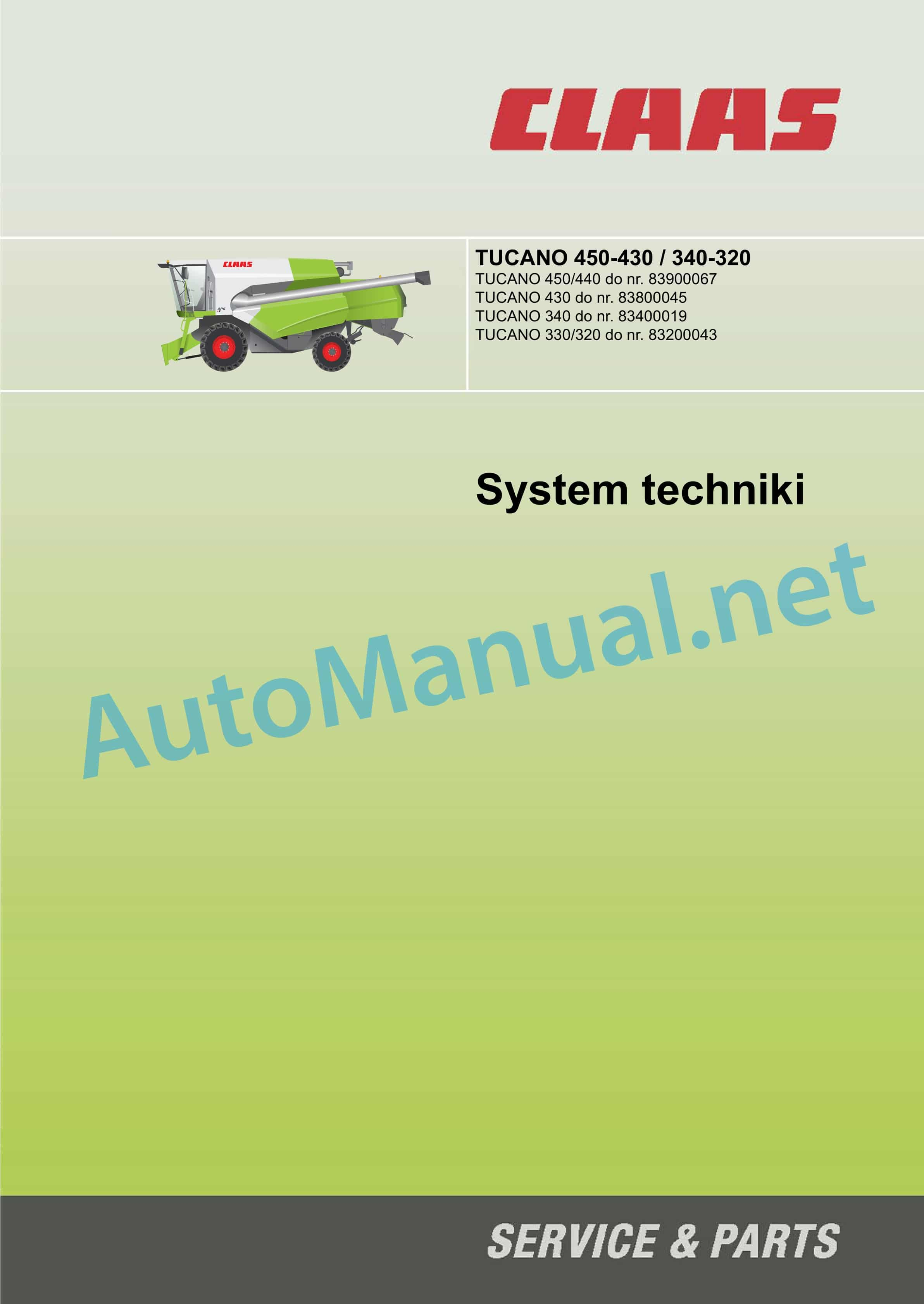
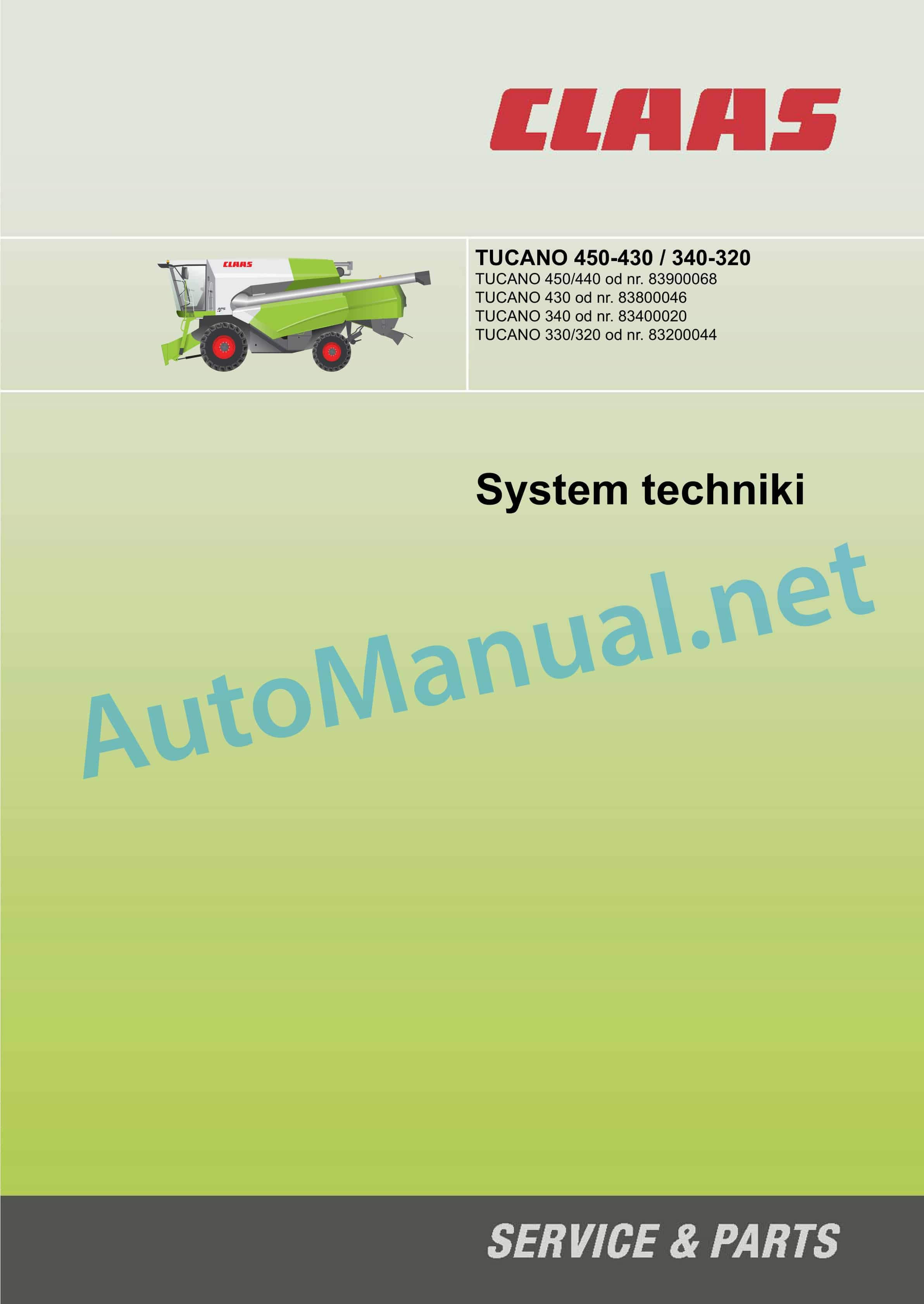
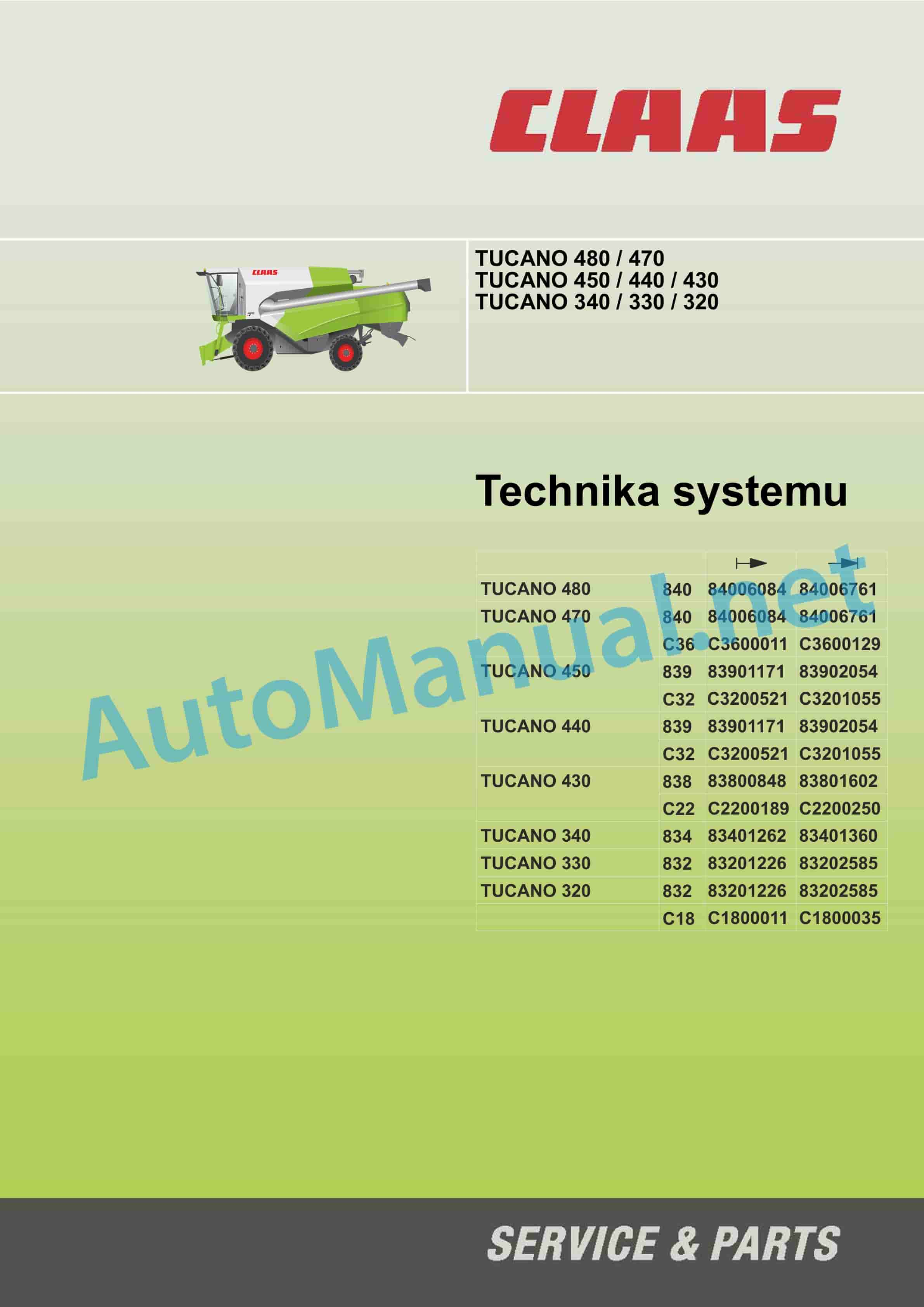
Claas TUCANO 340 (834) Combine Technical System PL
$150.00
- Model: TUCANO 340 (834) Combine
- Type Of Manual: Technical System
- Language: PL
- Format: PDF(s)
- Size: 232 MB
File List:
– 00 0290 223 3.pdf
– 00 0290 252 0.pdf
– 00 0290 647 1.pdf
– 00 0291 038 2.pdf
– 00 0292 125 1.pdf
00 0290 223 3.pdf
Table of Content:
1 Table of contents
2 Explanations CCN
2.1 CCN (CLAAS Component Number)
3 CCN (CLAAS Component Number)
4 Introduction
4.1 Scope of instruction
4.2 Visualizations-3D
5 01 Engine
5.1 DAIMLER – diesel engine start, diesel engine supervision
6 03 Vehicle
6.1 Hydrostatic drive – diesel engine Daimler
6.2 4-Trac
7 05 Steering
7.1 Steering system
7.2 Neutral function diagram
7.3 Function diagram of activated steering
7.4 Checking the steering system
8 09 Plumbing
8.1 Valve blocks
8.2 Vehicle hydraulic diagrams
8.3 Connection diagrams of the implement hydraulics
9 10 Electrics
9.1 Road driving function – turning on field driving
9.2 Function of the switch in the seat
9.3 CAN function (Daimler-Benz)
9.4 Signal function-T
9.5 Electrical unit
9.6 Modutiuction to connection diagrams
9.8 Machine electrical connection diagrams (SCM)
9.9 Work equipment electrical connection diagrams (SCM)
9.10 Cable bundles
9.11 Presentation of plug-in connectors
10 20 Material download
10.1 Raising / lowering the attachment
10.2 Switch implement on/off
10.3 Reversing the attachment
10.4 Raising / lowering the reel, automatic reel height
10.5 Reel extension/retraction
10.6 Changing the reel speed, automatic reel speed
10.7 Adjusting the cutterbar table VARIO
10.8 Manual transverse adjustment
10.9 Depreciation of the working attachment
11 26 Ground guidance
11.1 Auto-Contour (CAC) / Contour
12 41 Mocarnia
12.1 Turning on mocarni
12.2 Beating drum – change of speed
13 43 Cleaning
13.1 Blower – changing the number of revolutions
13.2 Adjusting the sieves – upper sieve
13.3 Adjusting the sieves – 61 Grain protection
15.1 Adjusting the unloading pipe
15.2 Emptying the grain tank
16 Diagnosis by error codes
16.1 FMI Error Codes (Failure Mode Indicator)
17 Part location
17.1 Hydraulics
17.2 Electrics
18 Index hase
00 0290 252 0.pdf
Table of Content:
1 TUCANO 480 / 470TUCANO 450 / 440 / 430TUCANO 340 / 330 / 320
2 Table of contents
3 Explanation CCN
3.1 CCN (CLAAS Component Number)
4 CCN (CLAAS Component Number)
5 Introduction
5.1 General instructions
6 01 Engine
6.1 0125 Injection system / fuel system
6.2 0150 Engine Mounted Parts
6.3 0155 Engine regulation
6.4 0165 Secondary exhaussteering axle
7.2 0335 Travel drive
8 04 Brakes
8.1 0405 Service brake
9 05 Steering
9.1 0505 Steering
9.2 0510 Automatic steering
10 09 Plumbing
10.1 0920 Valves
10.2 0980 Hydraulic wiring diagrams
11 10 Electrics / Electronics
11.1 1010 Electrical panel
11.2 1012 Sensors / modules
11.3 1015 Cable harnesses
11.4 1035 Operation / Multifunction lever
11.5 1040 Set size measurement
11.6 1080 Electrical wiring diagrams
11.7 1081 List of plugins
11.8 1085 Networks
12 12 Cab/driver platform
12.1 1230 Armchair
12.2 1240 Air conditioning
13 20 Material download
13.1 2002 Attachment
13.2 2010 Cutterbar table
13.3 2015 Nagarniacz
14 26 Ground guidance
14.1 2605 Auto-Contour
15 41 Threshing
15.1 4100 Threshing
15.2 4120 Threshing drum
16 43 Cleaning
16.1 4320 Sieves / sieve box
16.2 4325 Blower
17 60 Material placement / straw placement
17.1 6010 Straw chopper
18 61 Grain protection
18.1 6120 Grain tank – emptying
19 Diagnosis by error codes
19.1 FMI Error Codes (Failure Mode Indicator)
19.2 Fehlercodes Maschine
19.3 Fehlercodes Dieselmotor
20 Part location
20.1 Hydraulics
20.2 Electric
00 0290 647 1.pdf
Table of Content:
1 Table of contents
2 Explanations CCN
2.1 CCN (CLAAS Component Number)
3 CCN (CLAAS Component Number)
4 Introduction
4.1 Scope of instruction
4.2 Visualizations-3D
4.3 DAIMLER – diesel engine start, diesel engine supervision
5 03 Vehicle
5.1 Hydrostatic travel drive
5.2 4-Trac
6 05 Stee diagram
6.3 Function diagram of activated steering
6.4 Checking the steering system
7 09 Plumbing
7.1 Valve blocks
7.2 Vehicle hydraulics diagrams
7.3 Connection diagrams of the implement hydraulics
8 10 Electrics
8.1 Road driving function – turning on field driving
8.2 Function of the switch in the seat
8.3 CAN function (Daimler-Benz)
8.4 Signal function-T
8.5 Electrical unit
8.7 Introduction to connection diagrams
8.8 Machine electrical connection diagrams (SCM)
8.9 Connection diagrams for work equipment (SCM)
8.10 Presentation of plug-in connectors
9 20 Material download
9.1 Raising / lowering the attachment
9.2 Switch implement on/off
9.3 Reversing the attachment
9.4 Raising / lowering the reel, automatic reel height
9.5 Reel extension/retraction
9.6 Changing the reel speed, automatic reel speed
9.7 Adjusting the cutterbar table VARIO
9.8 Manual trhment
10 26 Ground guidance
10.1 Auto-Contour (CAC) / Contour
11 41 Mocarnia
11.1 Turning on mocarni
11.2 Crushing drum – change of speed
12 43 Cleaning
12.1 Blower – changing the number of revolutions
12.2 Adjusting the sieves – upper sieve
12.3 Adjusting the sieves – lower sieve
13 61 Grain protection
13.1 Adjusting the unloading pipe
13.2 Emptying the grain tank
14 Diagnosis by error codes
14.1 FMI Error Codes (Failure Mode Indicator)
15 Part location
15.1 Hydraulics
15.2 Electrics
16 Index hase
00 0291 038 2.pdf
Table of Content:
1 MB OM460LAMB OM502LAMB OM906LAMB OM926LA
2 Table of contents
3 Explanation CCN
3.1 CCN (CLAAS Component Number)
4 CCN (CLAAS Component Number)
5 In 6.3 0165 Secondary exhaust gas circuit
7 10 Electrics / Electronics
7.1 1012 Sensors / modules
7.2 1085 Networks
8 92 Diagnosis
8.1 Diagnosis by error codes
8.2 9220 Diesel Engine Fault Codes (J1939)
00 0292 125 1.pdf
Table of Content:
1 TUCANO 480 / 470
2 TUCANO 450 / 440 / 430
3 TUCANO 340 / 330 / 320
4 Table of contents
5 Explanation of CCN
5.1 CCN (CLAAS Component Number)
6 CCN (CLAAS Component Number)
6.1 CCN Index
7 Introduction
7.1 General instructions
8 01 Engine
8.1 0125 Injection system / fuel system
8.2 0150 Engine mounted parts
8.3 0155 Engine regulation
8.4 0165 Secondary exhaust gas circuit
9 03 Chassis
9.1 0330 Driven rear steering axle
9.2 0335 Travel drive
10 04 Brakes
10.1 0405 Service brake
11 05 Steering system
11.1 0505 Steering
11.2 0510 Automatic steering
12 09 Plumbing
12.1 0920 Valves
12.2 0980 Hydraulic wiring diagrams
13 10 Electrics / Electronics
13.1 1010 Electrical panel
13.2 1012 Sensors / modules
13.3 1015 Cable harnesses
13.4 1035 Operation / Multifunction lever
13.5 1040 Set size measurement
13.6 1080 Electrical wiring diagrams
13.7 1081 List of plugins
13.8 1085 Networks
14 12 Driver’s cab/bridge
14.1 1230 Armchair
14.2 1240 Air conditioning
15 20 Material download
15.1 2002 Attachment
15.2 2010 Cutterbar table
15.3 2015 Nagarniacz
16 26 Ground guidance
16.1 2605 Auto-Contour
17 41 Threshing
17.1 4100 Threshing
17.2 4120 Threshing drum
18 43 Cleaning
18.1 4320 Sieves / sieve box
18.2 4325 Blower
19 60 Material placement / straw placement
19.1 6010 Straw chopper
20 61 Grain protection
20.1 6120 Grain tank – emptying
21 Diagnosis by error codes
21.1 FMI Error Codes (Failure Mode Indicator)
21.2 Error codes
21.3 List of error codes J 1939 / engine diagnosis
22 Part location
22.1 Hydraulics
22.2 Electric
John Deere Parts Catalog PDF
John Deere Tractors 6300, 6500, and 6600 Parts Catalog CQ26564 (29SET05) Portuguese
John Deere Repair Technical Manual PDF
John Deere Repair Technical Manual PDF
John Deere Repair Technical Manual PDF
John Deere Repair Technical Manual PDF
John Deere Application List Component Technical Manual CTM106819 24AUG20
John Deere Repair Technical Manual PDF
John Deere Repair Technical Manual PDF
John Deere POWERTECH E 4.5 and 6.8 L Diesel Engines TECHNICAL MANUAL 25JAN08
John Deere Repair Technical Manual PDF
John Deere Repair Technical Manual PDF
John Deere Repair Technical Manual PDF

