Claas Tucano 430-420 (838) Combines Operator Manual EN
$50.00
- Model: Tucano 430-420 (838) Combines
- Type Of Manual: Operator Manual
- Language: EN
- Format: PDF(s)
- Size: 356 MB
File List:
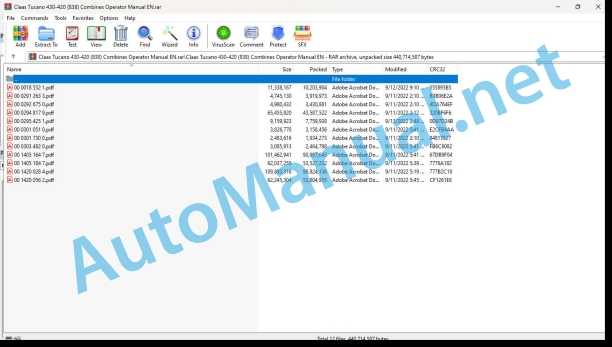
00 0018 552 1.pdf
00 0291 263 3.pdf
00 0292 675 0.pdf
00 0294 817 9.pdf
00 0295 425 1.pdf
00 0301 051 0.pdf
00 0301 730 0.pdf
00 0303 482 0.pdf
00 1405 164 7.pdf
00 1405 184 7.pdf
00 1420 028 4.pdf
00 1420 056 2.pdf
00 0018 552 1.pdf:
TELEMATICS Website
Table of contents
1 About this Concise Operator’s Manual
1.1 Notes on the manual
1.1.1 Validity of manual
1.1.2 Notes regarding the Concise Operator’s Manual
1.1.3 Notes on warranty
2 Safety
2.1 Intended use
2.1.1 Proper use
3 Product description
3.1 Overview and method of operation
3.1.1 TELEMATICS product variants
3.1.2 TONI (TELEMATICS on implements)
3.1.3 Fleet View
3.1.4 TELEMATICS basic
3.1.5 TELEMATICS advanced
3.1.6 TELEMATICS professional
3.1.7 TELEMATICS app
4 Operating and control elements
4.1 TELEMATICS overview
4.1.1 Illustration conventions of buttons and navigation elements
4.1.2 Symbols and colours
4.2 Menu structure
4.2.1 Start screen
4.2.2 TELEMATICS website site map
4.2.3 Main menu overview
4.2.4
4.2.5
4.2.6
00 0291 263 3.pdf:
TUCANO 470 – 320
Table of contents
1 To this operator’s manual
1.1 General Information
1.1.1 General instructions
1.1.2 Validity of manual
1.1.3 Handling of manual
1.1.4 Symbols and notes
1.1.5 Machine equipment
1.1.6 Technical specifications
2 Safety
2.1 Safety decals on the machine
2.1.1 Crop discharge / straw discharge
2.1.2 Safety decals
3 Machine description
3.1 Overview and method of operation
3.1.1 Engine overview
4 Operating and control elements
4.1 Cab / Operator’s platform
4.1.1 Vehicle information unit
4.2 Board computer / Indicators
4.2.1 Vehicle control display overview
5 Technical specifications
5.1 TUCANO 470 / 450 / 440 / 430 / 340 / 320 – Type 840 / 839 /838 / 834 / 832
5.1.1 Engine
5.1.2 Electrical/electronic equipment
5.1.3 Attachment parts / machine body weights
6 Machine preparation
6.1 Shutting down and securing the machine
6.1.1 Switch off and secure the machine
6.2 Loading the machine
6.2.1 Use of lifting gears
7 Operation
7.1 General Information
7.1.1 General warnings
7.2 Crop discharge / Swath discharge
7.2.1 Adjusting the straw chopper speed (TUCANO 450 / 440 / 430 / 340 / 320, drive on left side)
Reduce the straw chopper speed
Increasing the straw chopper speed
7.2.2 Straw chopper overview
7.2.3 Converting the straw chopper to swathing position
7.2.4 Converting the straw chopper to chopping position
7.2.5 Adjusting the inclination (Special Cut deflector plate spreader)
8 Faults and remedies
8.1 General Information
8.1.1 General warnings
8.2 Cab / Operator’s platform
8.2.1 Basic central terminal compartment
8.3 Electrical / Electronic equipment
8.3.1 Vehicle main fuse
8.3.2 Installation position of battery
8.3.3 Assist-starting (12 V / 24 V)
Assist-starting (12 V / 24 V)
Diesel engine assist-starting
9 Maintenance
9.1 General Information
9.1.1 General warnings
9.1.2 Permissible fuels
9.1.3 Urea solution
Use of urea solution
Purity / urea solution standard
Storage of urea solution in tanks / containers
Properties of urea solution at high / low outside temperatures
9.1.4 Welding work on combine harvester
9.2 Operating utilities
9.2.1 Lubricants
9.3 Service intervals
9.3.1 Every 10 operating hours or daily
9.3.2 Every 500 operating hours or annually
9.3.3 Every 1000 operating hours or every 2 years
9.3.4 Every 3 years
9.4 Engine
9.4.1 Cleaning the diesel engine surroundings
9.4.2 Refilling a machine with urea solution
9.4.3 Replacing the urea solution filter
9.5 Drives
9.5.1 General warnings
9.5.2 Adjusting the drives
9.5.3 Adjusting belt (R26)
9.5.4 Removing belt (R27)
9.5.5 Adjusting belt (R27)
9.5.6 Removing belt (R53)
9.5.7 Installing belt (R53)
9.5.8 Adjusting belt (R53)
9.6 Various components / Machine body
9.6.1 Replacing the dry-type air cleaner in the compressed air cleaning system
9.7 Lubrication chart
9.7.1 Lubrication points – 100 h left
9.7.2 Lubrication points – 500 h left
00 0292 675 0.pdf:
LEXION 770 – 620TUCANO 470 – 320
Table of contents
1 To this operator’s manual
1.1 General Information
1.1.1 Validity of manual
1.1.2 Symbols and notes
2 Operating and control elements
2.1 Cab / Operator’s platform
2.1.1 CEBIS control panel
2.2 Board computer CEBIS
2.2.1 General instructions – CEBIS
2.2.2 Vehicle control display overview
2.2.3 Vehicle control display overview
2.2.4 Harvest display overview
2.2.5 CRUISE PILOT harvest display overview
2.2.6 CEBIS direct menu overview
2.2.7 Understanding CEBIS fault code information
Understanding the type of fault code information
Understanding the format of fault code information
Clearing fault code information
Viewing the alarm history
Viewing active alarms
2.2.8 Symbols in windows
2.2.9 CEBIS direct menu
2.2.10 HOTKEY direct menu
2.2.11 Quick access menu
2.2.12 Main menu
2.2.13 Front attachment menu
2.2.14 Driving menu
2.2.15 AUTO PILOT menu
2.2.16 Machine settings menu
2.2.17 Crop settings menu
2.2.18 Recorder menu
2.2.19 Maintenance menu
2.2.20 CEBIS menu
00 0295 425 1.pdf:
1 Instructions
1.1 Allgemeine Hinweise
1.1.1 Handling of the connection
Text and Abbildungen
Gliederung mit Baugruppenstruktur
Suchen and Finden
Richtungsangaben
1.1.2 Instructions of the connection
1.1.3 Gltigkeit des Lieferumfangs
1.1.4 Strohhckslerbersicht
2 Sicherheit
2.1 Beachten
2.1.1 Sonders on the beach
2.1.2 Kennzeichnung von Warn- und Gefahrenhinweisen
3 Lieferumfang
3.1 Umbau von Getreide 1.1 Nachrustsatz
3.1.2 Nachrustsatz
3.1.3 Nachrustsatz
4.1 Allgemeine Hinweise
4.1.1 Allgemeine Warnhinweise
4.2 Strohhcksler auf But umrsten
4.2.1 Lieferumfang controls
4.2.2 Strohleitblech ausbauen (Strohhcksler mit Standardverteiler)
4.2.3 Schlegelmesser abschrauben (Getreide)
4.2.4 Schlegelmesser anschrauben (But)
4.2.5 Querschneide ausbauen (Strohhcksler Standard)
4.2.6 Querschneide zurckstellen (Strohhcksler Special Cut)
4.2.7 Automatic transmission (Strohhcksler Standard)
4.2.8 Heightened zurckschwenken (Strohhcksler Special Cut)
4.2.9 Winkelblech (Getreide) austauschen (Strohhcksler Standard)
4.2.10 Strohleitblech einbauen (Strohhcksler mit Standardverteiler)
4.2.11 SSeitenteilen einbauen (But)
4.2.12 Strohhcksler Antriebsdrehzahl ndern (But)
Strohhcksler Standard bis Maschinen-Nr. …
Strohhcksler Standard ab Maschinen-Nr. … anbereiten und durchfhren
4.3 Strohhcksler auf Getreide umrsten
4.3.1 Machine at the beginning
4.3.2 Strohhcksler Antriebsdrehzahl ndern (Getreide)
Strohhcksler Standard bis Maschinen-Nr. …
Strohhcksler Standard ab Maschinen-Nr. … and Strohhcksler Special Cut
All the machines
4.3.3 Spritztuch und Seitenteile ausbauen (Getreide)
4.3.4 Winkelblech (Getreide, Mais) (Strohhcksler Standard)
4.3.5 Strohleitblech ausbauen (Strohhcksler mit Standardverteiler)
4.3.6 Schlegelmesser abschrauben (But)
4.3.7 Schlegelmesser anschrauben (Getreide)
4.3.8 Querschneide einbauen (Strohhcksler Standard)
4.3.9 Querschneide vorstellen (Strohhcksler Special Cut)
4.3.10 General specificaler Standard)
4.3.11 Heightened loads (Strohhcksler Special Cut)
4.3.12 Strohleitblech einbauen (Strohhcksler mit Standardverteiler)
4.3.13 Probelauf vorbereiten und durchfhren
5 Arbeitseiablage / Strohablage
5.2.1 Querschneide einstellen (Strohhcksler Standard)
5.2.2 Querschneide einstellen (Strohhcksler Special Cut)
5.2.3 General instructions (Strohhcksler Standard)
5.2.4 Special Cut Slots (Strohhcksler Special Cut)
1 Introduction
1.1 General Information
1.1.1 How to use this manual
Texts and figures
Document structure based on subassemblies
Search and find
Directions
1.1.2 Validity of instructions
1.1.3 Validity of shipping package
1.1.4 Straw chopper overview
2 Safety precautions
2.1 Important
2.1.1 Important information
2.1.2 Identification of warning and danger signs
3 Package list
3.1 Conversion from grain to maize
3.1.1 Supplement
3.1.2 Supplementary kit
3.1.3 Supplementary kit
4 Conversion
4.1 General Information
4.1.1 General warnings
4.2 Converting the straw chopper to maize
4.2.1 Check shipping package
4.2.2 Removing the straw guide plate (straw chopper with sta4.2.3 Unscrew the free-swinging knives (grain)
4.2.4 Fitting the free-swinging knives (maize)
4.2.5 Removing the cross blade (standard straw chopper)
4.2.6 Resetting the cross blade (Special Cut straw chopper)
4.2.7 Removing the stationary knives (standard straw chopper)
4.2.8 Folding back the stationary knives (Special Cut straw chopper)
4.2.9 Replacing the angle plate (grain) (standard straw chopper)
4.2.10 Installing the straw guide plate (straw chopper with standard spreader)
4.2.11 Installing the deflector curtain with side elements (maize)
4.2.12 Changing the straw chopper drive speed (maize)
Standard straw chopper up to serial no. …
Standard straw chopper from serial no. … and Special Cut straw chopper
All machines
4.2.13 Prepare and carry out a test run
4.3 Converting the straw chopper to grain
4.3.1 Putting the machine out of action
4.3.2 Changing the straw chopper drive speed (grain)
Standard straw chopper up to serial no. …
Standard straw chopper from serial no. … and Special Cut straw chopper
All machines
4.3.3 Removing the deflector curtain and the side elements (grain)
4.3.4 Angle plate (grain, maize) (standard straw chopper)
4.3.5 Removing the straw guide plate (straw chopper with standard spreader)
4.3.6 Removing the free-swinging knives (maize)
4.3.7 Fitting the free-swinging knives (grain)
4.3.8 Installing the cross blade (standard straw chopper)
4.3.9 Setting the cross blade forward (Special Cut straw chopper)
4.3.10 Installing the stationary knives (standard straw chopper)
4.3.11 Folding the stationary knives forward (Special Cut straw chopper)
4.3.12 Installing the straw guide plate (straw chopper with standard spreader)
4.3.13 Prepare and carry out a test run
5 Fieldwork
5.1 General Information
5.1.1 General warnings
5.2 Crop receptacle / straw receptacle
5.2.1 Adjusting the cross blade (standard straw chopper)
5.2.2 Adjusting the cross blade (Special Cut straw chopper)
5.2.3 Adjust the stationary knives (standard straw chopper)
5.2.4 Adjusting the stationary knives (Special Cut straw chopper)
1 Introduction
1.1 General advice
1.1.1 Use of the instructions
Texts and illustrations
Classification by module structure
Seek and find
Directions
1.1.2 Validity of the notice
1.1.3 Validity of the parts provided
1.1.4 Overview of straw choppers
2 Safety Tips
2.1 Observe
2.1.1 Important
2.1.2 Marking of warnings and dangers
3 pieces supplied
3.1 Modification to move from cereals to corn
3.1.1 Retrofit clearance
3.1.2 Retrofit clearance
3.1.3 Retrofit clearance
4 Editing the edit
4.1 General advice
4.1.1 General safety advice
4.2 Modify the straw chopper to switch to corn
4.2.1 Check the parts provided
4.2.2 Remove the straw guide plate (straw chopper with standard distributor)
4.2.3 Unscrew the articulated knives (cereals)
4.2.4 Screw in the articulated knives (corn)
4.2.5 Remove the cross blade (standard straw chopper)
4.2.6 Retract the cross blade (Special Cut straw chopper)
4.2.7 Remove the counter-knives (standard straw chopper)
4.2.8 Pivot the counter-knives backwards (Special Cut straw chopper)
4.2.9 Replace the angle iron (cereals) (standard straw chopper)
4.2.10 Install the straw guide plate (straw chopper with standard distributor)
4.2.11 Install the anti-splash fabric with the side parts (corn)
4.2.12 Change the training regime of the straw chopper (corn)
Standard straw chopper up to machine No.
Standard straw chopper from machine No. … and Special Cut straw chopper
All machines
4.2.13 Prepare a test operation and carry it out
4.3 Modify the straw chopper for cereals
4.3.1 Turn off the machine
4.3.2 Change the training regime of the straw chopper (cereals)
Standard straw chopper up to machine No.
Standard straw chopper from machine No. … and Special Cut straw chopper
All machines
4.3.3 Remove the anti-splash fabric and the side pieces (cereals)
4.3.4 Angle iron (cereals, corn) (standard straw chopper)
4.3.5 Remove the straw guide plate (straw chopper with standard distributor)
4.3.6 Unscrew the articulated knives (corn)
4.3.7 Screw in the articulated knives (cereals)
4.3.8 Install the cross blade (standard straw chopper)
4.3.9 Advance the cross blade (Special Cut straw chopper)
4.3.10 Install the counter-knives (standard straw chopper)
4.3.11 Pivot the counter-knives forward (Special Cut straw chopper)
4.3.12 Install the straw guide plate (straw chopper with standard distributor)
4.3.13 Prepare a test operation and carry it out
5.1 General advice
5.1.1 General safety advice
5.2 Deposit of harvested product / deposit of straw
5.2.1 Adjust the cross blade (standard straw chopper)
5.2.2 Adjusting the cross blade (Special Cut straw chopper)
5.2.3 Adjust the counterblade (standard straw chopper)
5.2.4 Adjust the counter-knives (Special Cut straw chopper)
1 Introduction
1.1 General information
1.1.1 Application of the user manual
Testi e figure
Order by which the structure of the group is structured
Here and there
Directions information
1.1.2 Validity of the user manual
1.1.3 Validity of the supply package
1.1.4 View from inside the trinciapaglia
2 Sicurezza
2.1 How to operate
2.1.1 Important warnings
2.1.2 Warning and warning signal
3 Complessivo di fornitura
3.1 Modification of the corn grain
3.1.1 Improvement kit
3.1.2 Improvement kit
3.1.3 Improvement kit
4 Change
4.1 General information
4.1.1 General warnings
4.2 Transformation of trinciapaglia per mais
4.2.1 Check the component of the device
4.2.2 Show the blade to guide the blade (Trinciapaglia with standard blades)
4.2.3 Save the batten blade (cereal)
4.2.4 Avvitare the batten blade (but)
4.2.5 Smontaggio della mama transversele (standard trinciapaglia)
4.2.6 Arretramento de la miera transversele (trinciapaglia Special Cut)
4.2.7 Smontaggio delle controlame (standard trinciapaglia)
4.2.8 Ribbon all’indietro delle controle (Trinciapaglia Special Cut)
4.2.9 Sostituzione dangolare lamiera (cereal) (standard trinciapaglia)
4.2.10 Guide rail guide (Trinciapaglia with standard equipment)
4.2.11 Montaggio del telo in gomma con le parti laterali (but)
4.2.12 Change the transmission number of the transmission (but)
Trinciapaglia standard fino alla macchina Nr. …
Standard trinciapaglia from the machine Nr. … and Special Cut trinciapaglia
Shut up the machine
4.2.13 Preparation and preparation for operation
4.3 Modify the cereal trinciaglia
4.3.1 Please allow the machine to be used
4.3.2 Variation of the transmission number of the trinket (cereal)
Trinciapaglia standard fino alla macchina Nr. …
Standard trinciapaglia from the machine Nr. … and Special Cut trinciapaglia
Shut up the
4.3.3 Show the grain and side particles (cereals)
4.3.4 Lamiera angolare (cereal, corn) (standard trinciapaglia)
4.3.5 Show the blade to guide the blade (Trinciapaglia with standard blades)
4.3.6 Svitare the batten blade (but)
4.3.7 Add the battered blade (cereal)
4.3.8 Montaggio della mama transversale (standard trinciapaglia)
4.3.9 Posting in front of the cross blade (special cut trinciapaglia)
4.3.10 Montaggio delle controlame (standard trinciapaglia)
4.3.11 Ribbing in front of the control blade (Trinciapaglia Special Cut)
4.3.12 Guide rail guide (Trinciapaglia with standard equipment)
4.3.13 Preparation and preparation for operation
5 Practical use on the field
5.1 General information
5.1.1 General warnings
5.2 Product Deposit / Paglia Deposit
5.2.1 Registration of the cross lama (standard trinciapaglia)
5.2.2 Register the cross lama (Trinciapaglia Special Cut)
5.2.3 Controller registration (standard trinciapaglia)
5.2.4 Control blade registration (Special Cut trinket)
1 Introduction
1.1 General information
1.1.1 Using the instructions
Texts and figures
Construction with the construction of construction groups
Buscar y encontrar
Directional indications
1.1.2 Validate the instructions
1.1.3 Validate the suministro set
1.1.4 Sumario del picador de paja
2 Safety meds
2.1 Observer
2.1.1 Especially important
2.1.2 Signaling warnings and warnings
3 Suministro Set
3.1 Cereal to corn processing
3.1.1 Rear mounting game
3.1.2 Rear mounting game
3.1.3 Rear mounting game
4 Transformation
4.1 General information
4.1.1 General warnings
4.2 Modify the corn paddle picker
4.2.1 Checking the suministro set
4.2.2 Remove the paja guide cover (paja pin with standard distributor)
4.2.3 Destornillar las cuchillas picadoras (cereal)
4.2.4 Stirring the picadora knives (corn)
4.2.5 Remove the transverse cuchilla (standard paddle picker)
4.2.6 Place the transversal cuchilla at the side (Special Cut Paja Picador)
4.2.7 Remove the contracuchillas (standard paddle picker)
4.2.8 Put the contracuchillas in place (Special Cut pajamas picador)
4.2.9 Replace the chapa (cereal) angle (standard grain picador)
4.2.10 Install the paja guide cover (paja pin with standard distributor)
4.2.11 Montar london peto with the side pieces (maize)
4.2.12 Modifying the rotational speed of the rice cooker (corn)
Picador de paja estndar hasta la mquina nr. …
Picador de paja estndar de la mquina nr. … and picador de paja Special Cut
All the machines
4.2.13 Prepare and carry out a preview of the operation
4.3 Transform the picador from rice to cereal
4.3.1 Pion the machine for service
4.3.2 Changing the rotation rate of the grain harvester (cereal)
Picador de paja estndar hasta la mquina nr. …
Picador de paja estndar de la mquina nr. … and picador de paja Special Cut
All theside pieces (cereal)
4.3.4 Angulo de chapa (cereal, corn) (picador de paja standard)
4.3.5 Remove the paja guide cover (paja pin with standard distributor)
4.3.6 Destornillar las cuchillas picadoras (corn)
4.3.7 Atornillar las cuchillas picadoras (cereal)
4.3.8 Mount the transverse cuchilla (standard paddle picker)
4.3.9 Position the transverse cuchilla hacia delante (picador de paja Special Cut)
4.3.10 Montar las contracuchillas (picador de paja standard)
4.3.11 Place the contracuchillas hacia delante (picador de paja Special Cut)
4.3.12 Install the paja guide cover (paja pin with standard distributor)
4.3.13 Prepare and carry out a preview of the operation
5 Operational service
1 General information
5.1.1 General warnings
5.2 Deposit the material/deposit the paja
5.2.1 Adjust the transverse cuchilla (standard paddle picker)
5.2.2 Adjust the transverse cuchilla (picador de paja Special Cut)
5.2.3 Adjust the contracuchillas (standard paddle picker)
5.2.4 Adjust the contracuchillas (Special Cut paddle picker)
00 0301 051 0.pdf:
PROFI CAM 3
Table of contents
1 Introduction
1.1 Notes on the manual
1.1.1 Validity of manual
1.1.2 Information about this Operator’s Manual
1.1.3 Symbols and notes
1.1.4 Optional equipment
1.1.5 Qualified specialist workshop
1.1.6 Maintenance information
1.1.7 Warranty notes
1.1.8 Spare parts and technical questions
1.2 Intended use
1.2.1 Intended use
1.2.2 Reasonably foreseeable misuse
2 Safety
2.1 Identifying warnings
2.1.1 Hazard signs
2.1.2 Signal word
2.2 Safety rules
2.2.1 Meaning of Operator’s Manual
2.2.2 Observing safety decals and warnings
2.2.3 Optional equipment and spare parts
3 Product description
3.1 Overview and method of operation
3.1.1 How the PROFI CAM works
3.2 Identification plates and identification number
3.2.1 Position of identification plates
3.2.2 Explanation of PROFI CAM identification plate
3.3 Information on the product
3.3.1 CE marking
4 Operating and control elements
4.1 Camera system
4.1.1 Camera system monitor
4.2 Menu structure
4.2.1 Main menu
4.2.2
4.2.3
4.2.4
4.2.5
4.2.6
5 Technical specifications
5.1 PROFI CAM
5.1.1 Monitor
5.1.2 Camera
5.1.3 Switch box
5.1.4 Degree of protection against foreign bodies and water
6 Preparing the product
6.1 Shutting down and securing the machine
6.1.1 Switching off and securing the machine
6.2 Prior to operation
6.2.1 Carry out prior to operation
6.2.2 Installing the sun protection
6.2.3 Aligning the camera
6.2.4 Connecting the camera electrics
7 Operation
7.1 Monitor
7.1.1 Switching on the monitor
7.1.2 Calling up the menu
7.1.3 Setting a menu item
7.1.4 Setting the image orientation
7.1.5 Setting automatic screen darkening
7.1.6 Image mirroring
7.1.7 Setting the trigger view
7.1.8 Setting the follow-up time for trigger view
7.1.9 Setting the display mode
7.1.10 Activating/deactivating a display mode
8 Faults and remedies
8.1 Electrical and electronic system
8.1.1 Overview of problems on PROFI CAM camera system
8.1.2 Replacing the switch box fuse
9 Maintenance
9.1 Maintenance intervals
9.1.1 Every 10 operating hours or daily
9.2 Camera system
9.2.1 Checking the camera system for dirt
9.2.2 Cleaning the camera
9.2.3 Cleaning the switch box
9.2.4 Cleaning the monitor
10 Placing out of operation and disposal
10.1 General Information
10.1.1 Putting out of operation and disposal
11 Technical terms and abbreviations
11.1 Abbreviations
11.1.1 Units
11.1.2 Abbreviations
11.1.3 Technical terms
00 0301 730 0.pdf:
Diesel engines IIIB
Table of contents
1 Operation
1.1 Diesel engine
1.1.1 Start the diesel engine
EN – Start the diesel engine
No engine-relevant fault (DTC) detected
Engine-relevant fault (DTC) detected
00 0303 482 0.pdf:
PROFI CAM 4
Table of contents
1 Introduction
1.1 Notes on the manual
1.1.1 Validity of manual
1.1.2 Information about this Operator’s Manual
1.1.3 Symbols and notes
1.1.4 Optional equipment
1.1.5 Qualified specialist workshop
1.1.6 Maintenance information
1.1.7 Notes on warranty
1.1.8 Spare parts and technical questions
1.2 Intended use
1.2.1 Intended use
1.2.2 Reasonably foreseeable misuse
2 Safety
2.1 Identifying warnings
2.1.1 Hazard signs
2.1.2 Signal word
2.2 Safety rules
2.2.1 Meaning of Operator’s Manual
2.2.2 Structural changes
2.2.3 Optional equipment and spare parts
2.2.4 Operation only following proper putting into operation
2.2.5 Technical status
2.2.6 Respecting technical limit values
Respecting technical limit values
2.2.7 Hazards when driving on roads and fields
3 Product description
3.1 Overview and method of operation
3.1.1 How the PROFI CAM works
3.2 Identification plates and identification number
3.2.1 Identification plates
3.3 Information on the product
3.3.1 CE marking
4 Operating and display elements
4.1 Camera system
4.1.1 Camera system monitor
4.1.2 CEBIS
4.2 Menu structure
4.2.1 Main menu
4.2.2
4.2.3
4.2.4
4.2.5
4.2.6
5 Technical specifications
5.1 PROFI CAM
5.1.1 Monitor
5.1.2 Camera
5.1.3 Switch box
6 Preparing the product
6.1 Switching off and securing the machine
6.1.1 Switching off and securing the machine
6.2 Prior to putting into operation
6.2.1 Carry out prior to operation
6.2.2 Installing the sun protection
6.2.3 Aligning the camera
7 Operation
7.1 Monitor
7.1.1 Switching on the monitor
7.1.2 Calling up the menu
7.1.3 Setting a menu item
7.1.4 Setting the image orientation
7.1.5 Setting automatic screen darkening
7.1.6 Image mirroring
7.1.7 Setting the trigger view
7.1.8 Setting the follow-up time for trigger view
7.1.9 Setting the display mode
7.1.10 Activating/deactivating a display mode
8 Faults and remedies
8.1 Electric and electronic system
8.1.1 Overview of problems on PROFI CAM camera system
9 Maintenance
9.1 Maintenance intervals
9.1.1 Every 10 operating hours or daily
9.2 Camera system
9.2.1 Checking the camera system for dirt
9.2.2 Cleaning the camera
9.2.3 Cleaning the switch box
9.2.4 Cleaning the monitor
10 Putting out of operation and disposal
10.1 General information
10.1.1 Putting out of operation and disposal
11 Technical terms and abbreviations
11.1 Abbreviations
11.1.1 Units
11.1.2 Abbreviations
11.1.3 Technical terms
00 1405 164 7.pdf:
GPS PILOT
Table of contents
1 Introduction
1.1 General information
1.1.1 Validity of Manual
1.1.2 Information about this Operator’s Manual
1.1.3 Symbols and notes
1.1.4 Optional equipment
1.1.5 Qualified specialist workshop
1.1.6 Maintenance notes
1.1.7 Notes on warranty
1.1.8 Spare parts and technical questions
1.1.9 Licensing for road traffic
Sample report
Clearance certificate
General operating permit
1.2 Intended use
1.2.1 Intended use
1.2.2 Reasonably foreseeable misuse
2 Safety
2.1 Identifying warnings
2.1.1 Hazard signs
2.1.2 Signal word
2.2 Safety rules
2.2.1 Meaning of Operator’s Manual
2.2.2 Update of terminal software
2.2.3 Requirements made on all persons working with the product
2.2.4 Hazard areas
Hazard areas
2.2.5 Interaction between the control terminal and the machine or tractor
2.2.6 Structural changes
2.2.7 Optional equipment and spare parts
2.2.8 Use of USB devices
2.2.9 Operation only following proper putting into operation
2.2.10 Technical status
2.2.11 Hazard from damage on the product
2.2.12 Respecting technical limit values
Respecting technical limit values
2.2.13 Preparing the product for road travel
2.2.14 Hazards when driving on the road with an ISOBUS implement
Switching on the terminal during road travel.
2.2.15 Hazards when driving on the road and on the field
2.2.16 Electrocution by electrical system
2.2.17 Potentially fatal electric shock from overhead lines
2.2.18 Liquids under pressure
2.2.19 Maintenance operations and repair work
2.2.20 Driving with the GPS PILOT
Road travel
Fieldwork
2.2.21 Working with Task Control* and Section Control*
3 Product description
3.1 Overview and method of operation
3.1.1 Overview of GPS PILOT – Hydraulic system
3.1.2 Overview of GPS PILOT – Steer ready
3.1.3 Overview of GPS PILOT FLEX
3.1.4 Overview of GPS PILOT ex works
3.1.5 Overview of the S10 terminal
3.1.6 Overview of navigation computer (ECU)
3.1.7 Electric steering wheel
3.1.8 Overview of correction signals
EGNOS/WAAS/MSAS
Omnistar HP / XP / G2
RTK FIELD BASE and BASELINE HD
RTK FARM BASE
3.1.9 Module overview
BASELINE HD
RTK FIELD BASE
RTK (Motorola)
RTK FARM BASE
3.2 Safety devices
3.2.1 Automatic cut-out when the maximum speed is exceeded
3.2.2 Automatic cut-out when the speed falls below the minimum
3.2.3 Seat contact switch
3.2.4 Manual override
Electric steering wheel
3.3 Optional equipment
3.3.1 GPS L2*
3.3.2 GLONASS*
3.3.3 TURN IN*
3.3.4 AUTO TURN*
3.3.5 Task Control*
Task Control Basic*
Task Control Geo*
3.3.6 Section Control*
3.4 Identification plates and identification numbers
3.4.1 GPS PILOT identification plate
3.4.2 Identification plate of terminal
3.4.3 Identification plate of navigation controller
4 Operating and display elements
4.1 GPS PILOT
4.1.1 Master switch and drive switch
4.2 Overview of the S10 terminal
4.2.1 Layout conventions of buttons and displays
4.3 GPS PILOT menu structure
4.3.1 Start menu
Start menu without Task Control*
Start menu with Task Control*
4.3.2 Menu overview
4.3.3 Overview of display field
4.3.4
4.3.5
4.3.6
New Holland Service Manual PDF
John Deere Repair Technical Manual PDF
John Deere 16, 18, 20 and 24HP Onan Engines Component Technical Manual CTM2 (19APR90)
John Deere Repair Technical Manual PDF
John Deere Repair Technical Manual PDF
John Deere Repair Technical Manual PDF
John Deere Repair Technical Manual PDF
John Deere DF Series 150 and 250 Transmissions (ANALOG) Component Technical Manual CTM147 05JUN98
John Deere Repair Technical Manual PDF
John Deere Repair Technical Manual PDF
John Deere Repair Technical Manual PDF

