Claas V1050-V540 Vario Lexion Tucano (716) Combines Operator Manual ES
$50.00
- Model: V1050-V540 Vario Lexion Tucano (716) Combines
- Type Of Manual: Operator Manual
- Language: ES
- Format: PDF(s)
- Size: 11.8 MB
File List:
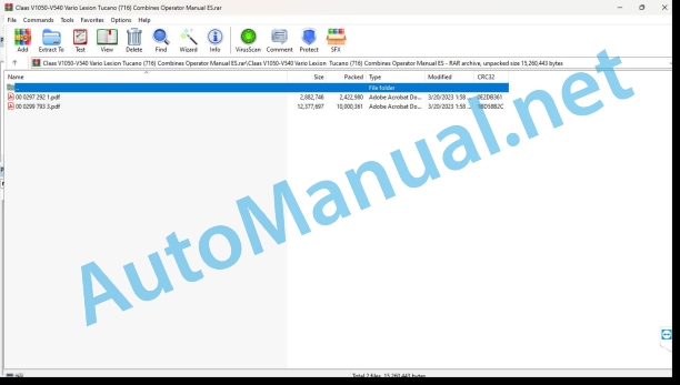
00 0297 292 1.pdf
00 0299 793 3.pdf
00 0297 292 1.pdf:
VARIO 1250 / 1050MAXFLEX 1250 / 1050MAXFLO 1250 / 1050C900 – C450V900 – V540
1. Introduction
1.1 Information on the instruction manual
1.1.1 Validity of the manual
1.1.2 Information on the instruction manual
2 Security
2.1 Recognize warning signs
2.1.1 Danger symbols
2.1.2 Keyword
2.2 Safety instructions
2.2.1 Instruction manual and other sources of information
Meaning of the instruction manual
2.2.2 Invisible laser beam of 1M laser category
2.2.3 Proper machine application
3 Technical data
3.1 LASER PILOT
3.1.1 LASER PILOT
4 Management
4.1 Address
4.1.1 Deploy the LASER PILOT
4.1.2 Adjust the LASER PILOT
Preparing the terrain
Adjust the LASER PILOT to the harvesting material
Adjust the LASER PILOT to the harvesting material
Prepare the adjustment process
Check the LASER PILOT setting
Vertically adjust the LASER PILOT
Control the horizontal preset of the LASER PILOT
Perform horizontal fine adjustment of the LASER PILOT
5 Incident and solution
5.1 Incident summary
5.1.1 LASER PILOT
00 0299 793 3.pdf:
VARIO V1050 – V540
1 Regarding this instruction manual
1.1 Information on the instruction manual
1.1.1 General instructions
1.1.2 Validity of the manual
1.1.3 Handling of the instruction manual
1.1.4 Symbols and indications
1.1.5 Machine equipment
1.1.6 Technical instructions
2 Security
2.1 Safety instructions
2.1.1 Take into account when working on the machine
2.1.2 General instructions
2.1.3 To take special account
2.1.4 Qualification of piloting and maintenance personnel
2.1.5 Proper Machine Application
2.1.6 Reasonably foreseeable misuse
2.1.7 General prescriptions for safety and accident prevention
2.2 Safety measures for use
2.2.1 Precautionaeasures
2.2.2 Pressurized and water
2.2.3 Risk of injury from hydraulic fluids
2.2.4 Prevention against burns
2.2.5 Oil
2.2.6 Prevention against fires and explosions
2.2.7 Pipes, tubes and hoses
2.2.8 Before each start-up
2.2.9 Commissioning of the machine
2.2.10 Driving on roads
2.2.11 Park
2.3 Safety measures in this manual
2.3.1 Warning and danger signs
2.4 Safety instructions on the machine
2.4.1 General information regarding warning symbols
2.4.2 Position of warning symbols
2.5 Safety devices
2.5.1 Place the safety support in the feed channel
2.5.2 Remove the safety support in the feed channel
2.5.3 Place the safety support of the windlass
2.5.4 Remove the safety supports from the reel
2.5.5 Install the cutter bar protection device
3 Machine Description
3.1 Summary and operation
3.1.1 Machine overview
3.1.2 Operating mode of the machine with cereal equipment
3.1.3 Machine operating mode with rapeseed equipment*
3.2 Safety devices
3.2.1 Friction clutch operating mode
3.3 Optional machine equipment
3.3.1 Optional equipment
3.3.2 Reduction of the speed
3.3.3 Rice cutting bar
3.4 Identification plates and identification numbers
3.4.1 Identification plate position
3.4.2 Explanation of machine nameplate
3.5 Machine information
3.5.1 Adhesive
4 Control and display instruments
4.1 Driver’s cabin/platform
4.1.1 Control desk
4.2 Harvest harvest
4.2.1 Cutting table adjustment
5 Technical data
5.1 V1050 / V900 / V750 / V660 / V600 / V540 – type 716
5.1.1 Eligible machines
5.1.2 Measurements
5.1.3 Weights
5.1.4 Cutting widths
5.1.5 Revolution regimes
5.1.6 Harvest harvest
5.1.7 Power unit
5.2 Inputs
5.2.1 Lubricants
5.2.2 Hydraulic oil
6 Preparation of the machine
6.1 Turn off the machine and secure it
6.1.1 Turn off the machine and secure it
6.2 Perform before commissioning
6.2.1 Perform before first start-up
6.2.2 Perform before each start-up
6.3 Load the head
6.3.1 Load and tie down the head
6.4 Assemble the head
6.4.1 Assemble the head
6.4.2 Prepare the bolting
6.4.3 Assemble the ratchet
6.4.4 Attach the head
6.4.5 Lock the head
6.4.6 Assemble the cardan shaft
Check chain length
6.4.7 Install multiple coupling
6.4.8 Remove the support legs
6.5 Disassemble the head
6.5.1 Disassemble the head
6.5.2 Place the table in transport position
6.5.3 Assemble the support legs
6.5.4 Remove multiple coupling
6.5.5 Dismantle articulated shaft
6.5.6 Unlock the head
6.5.7 Unhook the head
6.6 Electrical/electronic installation
6.6.1 AUTO CONTOUR* remove the safety equipment for transporting the probes
6.6.2 Installing the left rapeseed knife switch*
6.7 Harvest harvest
6.7.1 Dismantle the safety equipment for transporting the reel
6.7.2 Dismantle the safety equipment for transporting the reel cylinder
6.8 Power set
6.8.1 Adapt the scraper strips to the feed channel
Select scratching strips
Adjust the scraper bars
7 Management
7.1 Driving the machine
7.1.1 Prepare for road traffic
7.1.2 Prepare the field trip
7.2 Work application
7.2.1 Before field work
7.2.2 Control the collection of harvest material
7.3 Rapeseed harvest
7.3.1 Assemble the rapeseed equipment
7.3.2 Mount the rapeseed equipment belt
7.3.3 Assemble the plates of the rapeseed equipment
7.3.4 Assembling the rapeseed knives
7.3.5 Connect the hydraulic system
Right side of head
Left side of head
7.3.6 Connect the power supply
7.3.7 Mount the deflector canvas
7.3.8 Transform the LASER PILOT* for rapeseed harvesting
7.3.9 Put the hydraulic pump into operation
Put the pump into operation
7.4 Cereal harvest
7.4.1 Assemble the cereal equipment
7.4.2 Putting the hydraulic pump out of service
7.4.3 Transform the LASER PILOT* for cereal harvesting
7.4.4 Remove the deflector canvas
7.4.5 Separate the power supply
7.4.6 Separate the hydraulic system
Right side of head
Left side of head
7.4.7 Removing the rapeseed knife
7.4.8 Remove the plates from the rapeseed equipment
7.4.9 Assemble the cereal equipment belt
7.5 Address
7.5.1 Deploy LASER PILOT*
7.5.2 Deploy LASER PILOT*
7.5.3 Fold LASER PILOT*
7.6 Harvest harvest
7.6.1 Assemble the long crop divider
7.6.2 Dismantle the long crop divider
7.6.3 Adjusting the long crop divider
7.6.4 Deploy the long crop divider
7.6.5 Folding the long crop divider
7.6.6 Assemble the outer separator*
7.6.7 Remove the outer separator*
7.6.8 Assemble the short crop divider
7.6.9 Dismantle the short crop divider
7.6.10 Adjust the short crop divider
7.6.11 Deploy the short crop divider
7.6.12 Fold the short crop divider
7.6.13 Assemble the special crop divider
7.6.14 Dismantle the special crop divider
7.6.15 Deploy the special crop divider
7.6.16 Folding the special crop divider
7.6.17 Adjust the length of the table from the machine
7.6.18 Adjust the length of the table from the headstock
7.6.19 Adjust reel tine
7.7 Power set
7.7.1 Adjusting the feed auger scraper strip
7.7.2 Adjust feed auger position
Adjust the center bearing
7.7.3 Adjust the feed auger fingers
7.7.4 Remove extension of the auger plate
7.7.5 Mount extension of the auger plate
7.7.6 Adjust feed auger speed
Turn the gear wheel
Move the gear wheel
7.8 Mowing device
7.8.1 Assemble the crop lifters
7.8.2 Dismantle the crop lifters
7.8.3 Connecting the rapeseed knife
7.9 Floor guide
7.9.1 Adjust the skates
8 Incident and solution
8.1 Incident summary
8.1.1 Head
8.2 Hydraulic installation
8.2.1 Bleed the reel hydraulic cylinder
8.2.2 Bleed the hydraulic cylinders of the table regulation
8.3 Electrical/electronic installation
8.3.1 Adjust the table adjustment switch
8.3.2 Adjust windlass speed sensor
8.4 Harvest harvest
8.4.1 Adjust the basic adjustment of the reel height
Adjust the spring
8.4.2 Change the reel tines
8.4.3 Replacing the riveted nut of the reel
8.5 Power set
8.5.1 Change the feed auger fingers
8.6 Mowing device
8.6.1 Change the riveted blade
8.6.2 Change the screwed blade
8.6.3 Replacing double fingers
8.7 Floor guide
8.7.1 AUTO CONTOUR* adjust the potentiometer
Left side of head
Right side of head
9 Maintenance
9.1 Maintenance intervals
9.1.1 Management of maintenance intervals
9.1.2 Before harvest
9.1.3 After the first 100 hours of service
9.1.4 Every 10 hours of service or daily
9.1.5 Every 100 hours of service
9.1.6 Every 250 hours of service
9.1.7 Every 500 hours of service or annually
9.1.8 After harvest
9.2 General maintenance work
9.2.1 Preserve the head
9.2.2 Fixing material
9.3 Gears / clutch / cardan shaft
9.3.1 Check the gear oil level
9.3.2 Drain gear oil
9.3.3 Fill gear oil
9.4 Drives
9.4.1 Drive diagram
9.4.2 Remove the belt (R01)
9.4.3 Assemble the belt (R01)
9.4.4 Adjust the belt (R01)
9.4.5 Dismantle the chain (K01)
9.4.6 Assemble the chain (K01)
9.4.7 Adjust the chain (K01)
9.4.8 Dismantle the chain (K02)
9.4.9 Assemble the chain (K02)
9.4.10 Adjust the chain (K02)
9.4.11 Check chain tension
9.5 Hydraulic installation
9.5.1 Check the oil level in the hydraulic tank
9.5.2 Drain the oil from the hydraulic tank
9.5.3 Change the hydraulic tank return filter
9.5.4 Fill oil in the hydraulic tank
9.5.5 Check the hydraulic hoses
9.6 Address
9.6.1 Adjust the LASER PILOT* support
9.7 Harvest harvest
9.7.1 Check the table sliding beams
9.7.2 Adjusting the table sliding beams
9.7.3 Clean the table sliding beams
9.7.4 Clean up hedge funds
9.8 Power set
9.8.1 Check the feed auger friction clutch
9.9 Mowing device
9.9.1 Change blades
9.9.2 Adjust blade guide
9.10 Floor guide
9.10.1 Clean the skates
9.11 Greasing scheme
9.11.1 Grease the lubrication points every 10 hours of service
9.11.2 Grease the lubrication points every 100 hours of service
9.11.3 Grease points – 250 h
10 Service
10.1 Spare parts
10.1.1 Spare parts and technical questions
11 Decommissioning and waste disposal
11.1 General data
11.1.1 Decommissioning and waste disposal
12 EC declaration of conformity
12.1 V1050-V540 – Typ 716
12.1.1 EC declaration of conformity
John Deere Parts Catalog PDF
John Deere Harvesters 8500 and 8700 Parts Catalog CPCQ24910 Spanish
John Deere Repair Technical Manual PDF
John Deere 16, 18, 20 and 24HP Onan Engines Component Technical Manual CTM2 (19APR90)
John Deere Repair Technical Manual PDF
John Deere PowerTech M 10.5 L and 12.5 L Diesel Engines COMPONENT TECHNICAL MANUAL CTM100 10MAY11
John Deere Repair Technical Manual PDF
John Deere Repair Technical Manual PDF
John Deere DF Series 150 and 250 Transmissions (ANALOG) Component Technical Manual CTM147 05JUN98
John Deere Repair Technical Manual PDF
John Deere Repair Technical Manual PDF
John Deere Transmission Control Unit Component Technical Manual CTM157 15JUL05
John Deere Repair Technical Manual PDF


