Claas V750-V540 Vario Lexion (712) Combines Repair Manual EN
$300.00
- Model: V750-V540 Vario Lexion (712) Combines
- Type Of Manual: Repair Manual
- Language: EN
- Format: PDF(s)
- Size: 24.5 MB
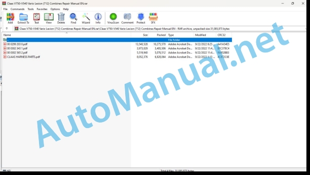
File List:
00 0299 203 0.pdf
00 0302 343 1.pdf
00 0302 565 2.pdf
CLAAS HARNESS PARTS.pdf
00 0299 203 0.pdf:
Contents
General information
Introduction
Introduction to the CLAAS REPAIR MANUAL
Key to symbols
Safety rules
Important information
Identification of warning and danger signs
Correct use of the round baler
General safety and accident prevention regulations
Leaving the combine harvester
Basic rule
Hydraulic accumulators
General repair information
Reason of damage
Spare parts
Transmission
Tensioning the steel roller chains
Taper ring fasteners
Installation:
Removal:
Self-locking bolts
Liquid locking compound
Correct application:
Correct installation of lock collar bearings
Correct installation of adapter sleeve bearings
Loosening the bearing:
Ferrule fittings on hydraulic lines
Pre-assembly:
Installation:
Re-installation:
Ferrule fitting leaks:
Progressive ring fittings on hydraulic lines
Pre-assembly:
Installation:
Progressive ring fitting leaks:
Taper fittings on hydraulic lines
Montage:
Some advice for speedy and correct repair work:
Tightening torques
Hydraulic screw fittings
Specifications
Lubricants chart
Drive diagram
General information on drives
Drive diagram, left-hand:
Drive diagram, right-hand:
Crop dividers
Crop dividers
Removing the crop dividers
Installing the crop dividers
Cutterbar trough – Cutter_x0011_bar
Cutterbar trough – Cutter bar
Removing the VARIO table
Mounting the VARIO table
Adjusting the potentiometer sensing band
Replacing the support bracket
Adjusting the slide bars
Cleaning the slide bars (19)
Cutterbar lock
Removing the cutterbar lock
Mounting and adjusting the cutterbar lock
Cutter bar
Removing the knives
Installing the knife
Adjusting the knife height
Main drive universal drive shaft
Removing the main drive universal drive shaft
Disassembling the main drive universal drive shaft
Assembling the main drive universal drive shaft
Mounting the main drive universal drive shaft
Intermediate drive, left-hand
Removing the left-hand intermediate drive
Installing the left-hand intermediate drive_x0011_shaft
Removing the hydraulic pump drive shaft
Installing the hydraulic pump drive shaft
Knife drive
Removing the knife drive belt (40)
Installing and adjusting the knife drive belt_x0011_(40)
Adjusting the knife drive pull cylinder
Adjusting the limit switch
Removing the pull cylinder of knife drive belt_x0011_(40)
Disassembling the pull cylinder of knife drive belt_x0011_(40)
Pull cylinder of knife drive belt (40), disassembled:
Assembling the pull cylinder of knife drive belt_x0011_(40)
Installing the pull cylinder of knife drive belt_x0011_(40)
Removing the wobble transmission (spare_x0011_part_x0011_no._x0011_643_x0011_656.1 and spare_x0011_part_x0011_no._x0011_643_x0011_656.2)
Disassembling the wobble transmission (spare_x0011_part_x0011_no._x0011_643_x0011_656.1 and spare part_x0011_no._x0011_643_x0011_656.2)
Assembling the wobble transmission (spare_x0011_part_x0011_no._x0011_643_x0011_656.1 and spare_x0011_part_x0011_no._x0011_643_x0011_656.2)
Installing the wobble transmission (spare part no._x0011_643_x0011_656.1 and spare part_x0011_no._x0011_643_x0011_656.2)
Removing the wobble transmission (spare_x0011_part_x0011_no._x0011_637_x0011_534.0)
Disassembling the wobble transmission (spare part no. 637 534.0)
Assembling the wobble transmission (spare part no. 637 534.0)
Installing the wobble transmission (spare part no._x0011_637_x0011_534.0)
Removing the deflection pulley of knife drive_x0011_(40)
Deflection pulley of knife drive (40), disassembled
Installing the jockey pulley of knife drive (40)
Removing the jockey pulleys of knife drive belt_x0011_(40)
Jockey pulley of knife drive (40), disassembled
Jockey pulley of knife drive (40), disassembled
Mounting the jockey pulleys of knife drive (40)
Intake auger
Intake auger drive
Removing the feed drive chain (41)
Installing and adjusting the feed drive chain_x0011_(41)
Removing the intake auger slip clutch
Intake auger slip clutch, disassembled
Mounting the intake auger slip clutch
Intake auger
Removing the left-hand intake auger bearing
Left-hand intake auger bearing, disassembled
Installing the left-hand intake auger bearing
Removing the left-hand intake auger drive shaft
Installing the left-hand intake auger drive shaft
Removing the right-hand intake auger bearing
Right-hand intake auger bearing, disassembled
Installing the right-hand intake auger bearing
Removing the right-hand intake auger flange
Installing the right-hand intake auger flange
Removing the adjusting shaft
Installing the adjusting shaft
Removing the control shaft
Installing the control shaft
Removing the intake auger finger
Installing the intake auger fingers
Removing the intake auger
Installing the intake auger
Reel drive belt / drive chains
Removing the reel drive chain (42)
Installing and adjusting the reel drive chain_x0011_(42)
Removing the reel drive chain (46)
Installing and adjusting the reel drive chain_x0011_(46)
Removing the sprocket of reel drive chain (46)
Mounting the sprocket of reel drive chain_x0011_(46)
Removing the reel drive belt (43)
Installing the reel drive belt_x0011_(43)
Removing the reel drive variable speed pulleys
Installing the reel drive variable speed pulleys
Reel drive universal drive shaft / angle drive
Removing the reel drive universal drive shaft with friction clutch
Disassembling the reel drive universal drive shaft with friction clutch
Reel drive universal drive shaft with friction clutch, disassembled:
Assembling the reel drive universal drive shaft with friction clutch
Mounting the reel drive universal drive shaft with friction clutch
Replacing the friction linings of the reel drive universal drive shaft with friction clutch
Mounting the friction linings of reel drive universal drive shaft with friction clutch
Adjusting the slip clutch
Removing the rear angle drive
Disassembling the rear angle drive
Rear angle drive, disassembled:
Assembling the rear angle drive
Mounting the rear angle drive
Removing the front angle drive
Disassembling the front angle drive
Front angle drive, disassembled:
Assembling the front angle drive
Mounting the front angle drive
Electric reel speed adjustment
Removing the electric reel variable-speed pulley
Electric reel variable-speed pulley, disassembled
Mounting the electric reel variable-speed pulley
Removing the electric reel speed adjustment (up to machine no.)
Disassembling the electric reel speed adjustment (up to machine no.)
Assembling the electric reel speed adjustment (up to machine no.)
Mounting the electric reel speed adjustment (up to machine no.)
Removing the electric reel speed adjustment (from machine no.)
Electric reel-speed adjustment, disassembled (from machine no.)
Mounting the electric reel-speed adjustment (from machine no.)
Removing the reel variable-speed drive bearing tube
Reel variable-speed drive bearing tube, disassembled
Assembling and installing the reel variable- speed drive bearing tube
Removing the spring-loaded reel variable- speed pulley
Spring-loaded reel variable-speed pulley, disassembled
Mounting the spring-loaded reel variable-speed pulley
Removing the reel
Installing the reel
Reel height adjustment (Basic setting)
Reel, disassembled
Removing the reel bearing
Installing the reel bearing
Removing the control rollers
Installing the control rollers
Checking and adjusting the track of control rollers
Removing the outside right-hand reel spider
Mounting the outside right-hand reel spider
Removing the outside left-hand control spider
Mounting the outside left-hand control spider
Removing the outside left-hand reel spider
Mounting the outside left-hand reel spider
Removing the reel shaft (on 7.50 m cutterbars)
Installing the reel shaft (on 7.50 m cutterbars)
Removing the centre reel spider
Mounting the centre reel spider
Hydraulic system / Electric system
Control valves
Removing the cutterbar control valve block
Cutterbar control valve block, disassembled
Assembling and installing the cutterbar control valve block
Replacing the non-return valve
Removing the Reel lower 2/2-way valve (Y23)
Reel lower 2/2-way valve (Y23), disassembled
Installing the reel lower 2/2-way valve (Y23)
Removing the reel backward 3/2-way valve_x0011_(Y25)
Reel backward 3/2-way valve (Y25), disassembled
Installing the reel backward 3/2-way valve_x0011_(Y25)
Removing the lock-up valve unit of reel backward valve (Y25)
_x0004_Disassembling the lock-up valve unit of reel backward valve (Y25)
Lock-up valve unit of reel backward valve_x0011_(Y25), disassembled:
Assembling the lock-up valve unit of reel backward valve (Y25)
Installing the lock-up valve unit of reel backward valve (Y25)
Hydraulic cylinders
Removing the left-hand double-acting reel height adjustment hydraulic cylinder
Disassembling the left-hand double-acting reel height adjustment hydraulic cylinder
Left-hand double-acting reel height adjustment hydraulic cylinder, disassembled:
Assembling the left-hand double-acting reel height adjustment hydraulic cylinder
Installing the left-hand double-acting reel height adjustment hydraulic cylinder
Removing the right-hand single-acting reel height adjustment hydraulic cylinder
Disassembling the right-hand single-acting reel height adjustment hydraulic cylinder
Right-hand single-acting reel height adjustment hydraulic cylinder, disassembled:
Assembling the right-hand single-acting reel_x0011_height_x0011_adjustment_x0011_hydraulic_x0011_cylinder
Installing the right-hand single-acting reel height adjustment hydraulic cylinder
Removing the reel horizontal adjustment hydraulic cylinder
Disassembling the reel horizontal adjustment hydraulic cylinder
Reel horizontal adjustment hydraulic cylinder, _x0004_disassembled:
Assembling the reel horizontal adjustment hydraulic cylinder
Installing the reel horizontal adjustment hydraulic cylinder
Removing the VARIO table hydraulic cylinder
Disassembling the VARIO table hydraulic cylinder
VARIO table hydraulic cylinder, disassembled:
Assembling the VARIO table hydraulic cylinder
Installing the VARIO table hydraulic cylinder
Hydraulic motors / pumps
Removing the rape side cutter hydraulic pump
Mounting the rape side cutter hydraulic pump
00 0302 343 1.pdf:
PROFI CAM 3
Table of contents
General information
Marking of warnings and hazard prevention notes
First-aid measures
CCN explanation
CCN (CLAAS Component Number)
Electric system standard
Overview
Hydraulic system standard
Overview
CCN (CLAAS Component Number)
10 Electrical / Electronic equipment
1030 Board computer / Indicators
Camera system
Description of function
1097 Testing / Measuring / Adjusting
Testing / measuring / adjusting the PROFI CAM
Checking the fuse in the video channel select box (C102)
Testing the video camera connector (C055)
1098 Fault / remedy
Fault / remedy PROFI CAM
The video monitor (C101) shows no image or cannot be switched on (indicator light fails to light up)
Video monitor (C102) displays a blue image either permanently or temporarily
The video monitor image is blurred
Replacing the fuse in the video channel select box (C102)
Connection and connecting cable with video camera (C055)
00 0302 565 2.pdf:
Sensor system
Table of contents
CCN explanation
CCN (CLAAS Component Number)
Electric system standard
Overview
Hydraulic system standard
Overview
CCN (CLAAS Component Number)
Introduction
Safety rules
Safety and hazard information
10 Electrical / Electronic equipment
1097 Testing / Measuring / Adjusting
Test report of the angle sensor (0011780.x)
Application of test report
Required tools
Test report of the angle sensor (0011780.x)
Testing / Measuring / Adjusting of angle sensor (0011780.x)
1. Reason for test
2. Mechanical test of angle sensor
3. Electric test with CDS
4. Electric test with multimeter
5. Mechanical test of connecting cable
Completing the machine
Test report of position and speed sensors
Application of test report
Required tools
Sensor variants
Part numbers of speed sensors
Part number of position sensor
Test report of position and speed sensors
Testing / measuring / adjusting of position and speed sensors
1. Reason for test
2. Mechanical test
3. Electric test with CDS
4a. Installation dimensions
Check of installation dimension
Installation dimensions of gearbox speed sensor (0011 799.x) and cam speed sensor (0011 810.x)
Installation dimension of position sensor (0011 815.x)
4b. Installation position
Centring of sensor
Metal-free zone
5. Electric test with multimeter
Voltage measurement
Direction of rotation and speed sensor (0011 605.x)
Measured values table
6. Mechanical test of connecting cable
Completing the machine
Test report of the urea sensor (00 0773 207 x)
Application of test report
Required tools
Parts number of the urea sensor
Test report of the urea sensor
Testing / measuring / adjusting urea sensor
1. Reason for test
2. Mechanical test
3. Mechanical test of connecting cable
4. Electric test with multimeter
5. Component test with the CDS
CLAAS HARNESS PARTS.pdf:
CLAAS HARNESS PARTS
Table of contents
10 Electrical / Electronic equipment
1081 Overview of connectors
CLAAS HARNESS PARTS (CHP)
John Deere Repair Technical Manual PDF
John Deere 16, 18, 20 and 24HP Onan Engines Component Technical Manual CTM2 (19APR90)
John Deere Repair Technical Manual PDF
John Deere Repair Technical Manual PDF
John Deere DF Series 150 and 250 Transmissions (ANALOG) Component Technical Manual CTM147 05JUN98
John Deere Parts Catalog PDF
John Deere Tractors 7500 Parts Catalog CPCQ26568 30 Jan 02 Portuguese
New Holland Service Manual PDF
John Deere Repair Technical Manual PDF
John Deere Transmission Control Unit Component Technical Manual CTM157 15JUL05
John Deere Repair Technical Manual PDF
John Deere Application List Component Technical Manual CTM106819 24AUG20
John Deere Repair Technical Manual PDF
John Deere Repair Technical Manual PDF
John Deere PowerTech M 10.5 L and 12.5 L Diesel Engines COMPONENT TECHNICAL MANUAL CTM100 10MAY11
John Deere Repair Technical Manual PDF

