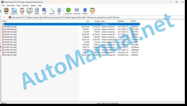
Claas Variant 370 (771) Balers Operator Manual EN
$50.00
- Model: Variant 370 (771) Balers
- Type Of Manual: Operator Manual
- Language: EN
- Format: PDF(s)
- Size: 185 MB
File List:
00 0288 354 6.pdf
00 0290 499 0.pdf
00 0290 518 0.pdf
00 0292 273 0.pdf
00 0293 389 3.pdf
00 0294 290 7.pdf
00 0295 237 5.pdf
00 0296 870.0.pdf
00 0301 051 0.pdf
00 0304 150 0.pdf
00 2348 408 0.pdf
00 2348 427 0.pdf
00 0288 354 6.pdf:
VARIANT 450VARIANT 470
Table of contents
1 Introduction
1.1 General information
1.1.1 Manual validity
1.1.2 Information about this Operator’s Manual
1.1.3 Symbols and notes
1.1.4 Optional equipment
1.1.5 Qualified specialist workshop
1.1.6 Maintenance notes
1.1.7 Notes on warranty
1.1.8 Spare parts and technical questions
1.2 Intended use
1.2.1 Using in line with intended usage
1.2.2 Reasonably foreseeable misuse
2.1 Identifying warnings
2.1.1 Hazard signs
2.1.2 Signal word
2.2 Safety rules
2.2.1 Importance of Operator’s Manual
2.2.2 Observing safety decals and warnings
2.2.3 Requirements for all persons working with the machine
2.2.4 Children in danger
2.2.5 Hazard areas
2.2.6 Presence between tractor and machine
2.2.7 Persons riding on the machine
2.2.8 Hitching the tractor to the machine
2.2.9 Danger of injury from rotating shafts
2.2.10 Structural alterations
2.2.11 Optional equipment and spare parts
2.2.12 Controlling the tractor when it is running
2.2.13 Operation only after proper putting into operation
2.2.14 Technical condition
2.2.15 Danger from damage to the machine
2.2.16 Complying with technical limit values
2.2.17 Danger from continued running of machine parts
2.2.18 Keeping safety devices functional
2.2.19 Personal protective equipment
2.2.20 Wearing suitable clothing
2.2.21 Removing dirt and loose objects
2.2.22 Preparing the machine for road travel
2.2.23 Risks when driving on the road and in the field
2.2.24 Parking the machine safely
2.2.25 Unsupervised parking
2.2.26 Unsuitable operating materials
2.2.27 Safe handling of operating and auxiliary utilities
2.2.28 Environmental protection and disposal
2.2.29 Fire prevention
2.2.30 Highly dangerous electric shock from the overhead power lines
2.2.31 Electrocution by electrical system
2.2.32 Pressurised fluids
2.2.33 Compressed air
2.2.34 Hot surfaces
2.2.35 Working on machine only after shutting it down
2.2.36 Maintenance work and repairs
2.2.37 Raised machine parts and loads
2.2.38 Risks related to welding work
2.3 Safety decals
2.3.1 Layout of safety decals
2.3.2 Location of safety stickers
3 Machine description
3.1 Existing models
3.1.1 Machine description
3.2 Overview and functions
3.2.1 Left-hand side
3.2.2 Right-hand side
3.2.3 Roller identification
3.3 Safety equipment
3.3.1 Indicator lights
3.3.2 Reflective equipment
Clearance reflectors
3.3.3 Jack stand
3.3.4 Chocks
3.3.5 Retaining cable*
3.3.6 Locking the tailgate
3.3.7 Locking the pick-up
3.3.8 Extinguisher
3.3.9 Main gearbox output protection, without twine tying
3.4 Working and service areas
3.4.1 General points
3.4.2 Front section of the baler
3.5 Identification plate and serial number
3.5.1 Replacement parts and technical information
3.5.2 Serial number, identification number or VIN code
3.5.3 Machine identification plate
Identification plate for a machine with European certification
Identification plate for a machine without European certification
Identification plate for countries in the Customs Union (Belarus, Kazakhstan, Russia)
3.5.4 Axle identification plate
3.5.5 Drawbar identification plate*
3.6 General operating principle
3.6.1 Baling cycle
3.7 Information on the machine
3.7.1 Location of information stickers
3.8 Control terminal
3.8.1 Control terminal*
3.9 Transmission and drive
3.9.1 Transmission
3.9.2 Drive
3.9.3 Drive chains
3.9.4 Pick-up drive
3.9.5 Rotor drive
3.10 Coupling frame
3.10.1 Types of hitch
3.11 Crop feeding
3.11.1 Pick-up
3.11.2 Crop guard
3.11.3 Short crop plate*
3.11.4 Roller crop press*
3.12 Feeder unit
3.12.1 Rotor
3.13 Baling system
3.13.1 Bale chamber and belts
3.13.2 Soft centre
3.13.3 Managing the peripheral layers
3.13.4 Bale chamber filling indicator*
3.14 Tying system
3.14.1 Tying types and processes
3.14.2 Standard tying
3.14.3 Twine tying
3.14.4 Net tying
3.14.5 Extra wide net tying*
3.14.6 Tying feed plate
3.14.7 Tying process
3.14.8 Twine/net box
3.15 Bale discharge
3.15.1 Bale ramp
3.16 Lubricating oil system
3.16.1 Automatic chain lubrication
3.17 Hydraulic system
3.17.1 Baler hydraulic block
3.17.2 Active hydraulics
3.18 Equipment
3.18.1 Ladder
3.18.2 Step
3.18.3 Modules
3.18.4 Anti-theft device
4 Operating and display elements
4.1 OPERATOR
4.1.1 Presentation
4.1.2 Description of the OPERATOR menus
4.1.3 Description of the simplified* OPERATOR menu
5 Technical specifications
5.1.1 Dimensions
5.1.2 Weight
5.1.3 Hitching
5.1.4 Universal drive shaft
5.1.5 Feeding and baling
5.1.6 Tying device
5.1.7 Wheels
5.1.8 Hydraulic circuit
5.1.9 Bolt tightening torques
5.1.10 Greasing and lubrication
5.1.11 Noise level
5.2 Safety devices
5.2.1 Shear bolt
5.2.2 Cut-out clutch
5.3 Operating utilities
5.3.1 Lubricants
5.3.2 Tying twine
5.3.3 Tying net
5.4 Tractor
5.4.1 Power required
5.4.2 Maximum authorised weight of the towing vehicle
5.4.3 Hitching
5.4.4 Power take-off
5.4.5 Hydraulic oil and circuit
5.4.6 Electrical connections
5.4.7 Hydraulic connections
6 Machine preparation
6.1 Switching off and securing the machine
6.1.1 Stopping and securing the tractor and machine
6.2 Adapting the tractor
6.2.1 Checking the protective guard on the tractor PTO shaft
6.2.2 Configuring the tractor air brake system
6.2.3 Installing the OPERATOR*
6.2.4 Battery cable*
6.3 Adapting the machine
6.3.1 Recommendations
6.3.2 Adapting clevis hitch / swinging drawbar
Drawbar arm
Drawbar in bottom position
Drawbar in upper position
Hitching device
Tightening torques for the drawbar arm bolts and hitching device bolts
6.3.3 Overlap of the universal drive shaft
6.3.4 Adapting the length of the universal drive shaft
6.3.5 Conversion kit – 8 splines*
6.4 Hitching the machine
6.4.1 Retaining cable*
6.4.2 Locking the hitch
6.4.3 Universal drive shaft safety advice
6.4.4 Fitting the universal drive shaft
6.4.5 Identifying the hydraulic hoses
6.4.6 Connection to the tractor’s double action control valves
6.4.7 Identifying the electrical cables
6.4.8 Lighting
6.4.9 Power supply for the baler and the OPERATOR*
6.5 Preparing fieldwork
6.5.1 Pick-up wheels
6.5.2 Pick-up height
6.5.3 Roller crop press*
6.6 Twine tying
6.6.1 Twine quality
6.6.2 Preparation
6.6.3 Adjusting the twine tensioner
6.6.4 Fitting the reels
6.6.5 Threading the twine
6.6.6 Selecting twine tying*
6.7 Net tying
6.7.1 Quality of the net
6.7.2 Preparation
6.7.3 Fitting the net
Position of the net roller
Position of the
6.7.4 Selecting net tying*
6.8 Loading the machine
6.8.1 Lashing the baler
6.8.2 Lifting points
Lifting eyes
Lifting points
6.8.3 Lifting
7 Operation
7.1 General information
7.1.1 Baler user
7.1.2 Opening the flaps and covers
Side flaps
Opening the side flaps
Closing the side flaps
Left pick-up housing
7.1.3 Raising / lowering the pick-up
7.1.4 Opening / closing the tailgate
7.1.5 Resetting the net knife
7.2 Travelling with the baler
7.2.1 Checking the equipment
7.2.2 Preparing for transportation
7.2.3 Travelling on the road
7.2.4 Arriving at the field
7.2.5 Driving in fields
7.2.6 Parking
7.3 Before each usage
7.3.1 Reminders
7.3.2 Universal drive shaft
7.3.3 Baler maintenance
7.3.4 Checking the equipment
7.3.5 Periods of very hot weather
7.4 Commissioning in the field
7.4.1 User advice
7.4.2 Starting the machine
7.5 Specific use
7.5.1 Use for wilted silage
Tailgate belt guides
7.6 Pick-up
7.6.1 Important
7.7.1 Reminders
7.7.2 Selecting twine tying or net tying*
7.7.3 Setting the number of twine wraps with standard tying
7.7.4 Setting the number of net wraps with standard tying
7.7.5 Setting the number of net wraps with standard Extra wide* tying
7.7.6 Adjusting the net brake
7.7.7 Replacing the net roller
7.8 Bale parameters
7.8.1 General points
7.8.2 Settings advised for dry crop (straw or hay)
Bale parameters
Soft centre parameters
Baler equipped with OPERATOR with simplified menu
Baler equipped with OPERATOR
7.8.3 Recommended settings for wilted silage
7.9 OPERATOR
7.9.1 Counters menu
7.9.2 Bale parameter settings
Bale and soft centre settings
Diameter of the outer layer of the bale
Correction of the bale diameter
Pressure of the outer layer of the bale
Soft centre density and diameter
Net tying* settings
Twine tying* settings
Tying delay
Selecting the tying type
Alert delay before tying start
Restoring the factory settings
7.9.3 Name of setting mode
7.9.4 Baling / tying process
7.9.5 Baling pressure
7.9.6 Manual tying start
7.9.7 Tying delay
7.9.8 Bale chamber filling indicator*
7.9.9 Faults
7.9.10 Monitoring the sensors and actuators
7.10 OPERATOR with simplified menu
7.10.1 Bale parameter settings
Setting the tying delay
Tying delay
7.10.2 Baling / tying process
7.10.3 Baling pressure
7.10.4 Manual tying start
7.10.5 Tying delay
7.10.6 Bale chamber filling indicator*
7.10.7 Faults
7.11 Unblocking the baler
7.11.1 How can blockages be avoided?
7.11.2 Safety advice
7.11.3 Unblocking the pick-up
7.11.4 Unblocking the baler
7.12 After use
7.12.1 Reminders
7.12.2 Securing the baler
7.12.3 Daily checks
7.12.4 Daily cleaning
7.12.5 Uncoupling the baler
7.13 Unhitching the machine
7.13.1 Retaining cable*
7.13.2 Uncoupling the baler
8 Faults and remedies
8.1 General information
8.1.1 Sensors
8.2 Hydraulic system
8.2.1 Hydraulic block
8.2.2 Baling pressure
8.2.3 Rotor
8.2.4 Tailgate
8.3 OPERATOR
8.3.1 Baling pressure
8.3.2 Oversize
8.3.3 Bale discharge
8.3.4 Twine knife
8.3.5 Electric circuit
8.4.1 Twine tying
8.4.2 Net tying
8.5 Lubricating oil system
8.5.1 Cause of the problems
8.5.2 Resolving problems
8.6 Greasing system
8.6.1 Cause of the problems
8.6.2 Resolving problems
8.7 Other functions
8.7.1 General functions
9 Maintenance
9.1 General maintenance information
9.1.1 Maintenance and safety advice
9.1.2 Wheels and tyres
9.1.3 Brakes
9.1.4 Hydraulic circuit
9.1.5 V-belt
9.1.6 Chains
9.1.7 Universal drive shaft
9.1.8 Safety device
9.1.9 Inductive sensors
9.2 Maintenance schedules
9.2.1 Before the harvest
9.2.2 After the first 10 hours of operation
9.2.3 After the first 50 hours of operation
9.2.4 Every 8 hours of operation or every day
9.2.5 Every 50 hours of operation
9.2.6 Every 100 hours of operation
9.2.7 Every 250 hours of operation
9.2.8 Every 500 hours of operation or every year
9.3 Lubrication plan
9.3.1 Important
9.3.2 Lubrication intervals
9.3.3 Lubrication points – 8 h
9.3.4 Lubrication points – 50 h
9.3.5 Lubrication points – 100 h
9.3.6 Lubrication points – 250 h
9.4 Maintenance operations gearbox
9.4.1 540 rpm drive gearbox
9.4.2 1000 rpm drive gearbox
9.4.3 Universal drive shaft shear bolt
9.5 Maintenance operations axle and wheels
9.5.1 Checking the tyres
9.5.2 Checking the wheel tightness
9.5.3 Lifting points
9.5.4 Changing the wheels
9.5.5 Wheel hub
9.6 Maintenance operations hitch
9.6.1 Drawbar and hitching device mounting
Checking the drawbar and hitching device mounting
9.7 Maintenance operations hydraulic system
9.7.1 Hydraulic hoses
Hose placement
9.7.2 Filter
9.8 Maintenance operations pick-up
9.8.1 Pick-up
9.8.2 Pick-up shear bolt*
9.9 Maintenance operations feeder unit
9.9.1 Rotor cut-out clutch
9.10 Maintenance operations baling chamber
9.10.1 Loosening
9.10.2 Checking wear
9.10.3 Repair
9.10.4 Replacing a belt
9.10.5 Replacing a complete set
9.10.6 Centring endless belts
If the belts are still incorrectly centred
If the belts are centred correctly
9.10.7 Roller No.1
9.10.8 Roller No.5
9.10.9 Drive springs
9.10.10 Tailgate eccentric rings
9.11 Maintenance operations tying
9.11.1 Twine tying
9.11.2 Net tying
9.11.3 Tying feed plate
9.11.4 Cleaning the tying clutch
9.12 Maintenance operations bale discharge
9.12.1 Bale ramp
9.13 Maintenance operations lubrication system
9.13.1 Chain lubrication
9.14 Maintenance operations greasing system
9.14.1 Manual lubrication
9.15 Maintenance operations machine body
9.15.1 Side flaps
9.15.2 Twine box*
9.15.3 Extinguisher*
9.15.4 Tailgate inductive sensor
9.16 Winter storage
9.16.1 General points
9.16.2 Cleaning
9.16.3 Cleaning surfaces with stickers
9.16.4 Lubricating
9.16.5 Maintenance
9.16.6 Storage
10 Putting out of operation and disposal
10.1 General information
10.1.1 Removal from service and disposal
11 EC declaration of conformity
11.1 General information
11.1.1 Declaration of Conformity for EC
00 0290 499 0.pdf:
1 Introduction
1.1 General information
1.2 Equipped machines
2 Security signs
2.1 Important
2.1.1 General information
2.1.2 Utilization compliant with the destination
2.2 Safety notices
2.2.1 Characterization of the indications on the dangers
2.2.2 General signs for safety and prevention of accidents
2.2.3 Stationing the machine
3 Lots of pieces
3.1 Rouleau kit N_x001E_ 5 – 4 courroies – 00 0857 297 0
3.2 Rouleau kit N_x001E_ 5 – 5 courroies – 00 0857 298 0
4 Assembly instructions
4.1 Introduction
4.1.1 General information
4.2 Dépose du rouleau N˚ 5
4.2.1 Press security
4.2.2 Preparation of the press
4.2.3 Dépose du rouleau N˚ 5
4.3 Reassembly of the machine
4.3.1 Remontage rouleau N_x001E_ 5
4.3.2 Remontage de l’entraînement
4.3.3 Function tests
5 Grass plan
5.1 Graissage de la presse
5.2 Greasing points
5.2.1 Greases and oils of lubrication
5.2.2 Greasing intervals
5.3 Graissage manual de la presse
5.3.1 Côté left – every 10 hours
5.3.2 Côté droit – to10 h
1 Einleitung
1.1 Allgemeines
1.2 Auszurüstende Maschinen
2 Sicherheitsvorschriften
2.1 Wichtig
2.1.1 Allgemeines
2.1.2 Benutzung gemäß Zweckbestimmung
2.2 Sicherheitsvorschriften
2.2.1 Kennzeichnung der Gefahrenhinweise
2.2.2 Allgemeine Vorschriften zur Sicherheit und Unfallverhütung
2.2.3 Parking of the Machine
3 Stückliste
3.1 Set für Walze Nr. 5 – 4 Bands – 00 0857 297 0
3.2 Set für Walze Nr. 5 – 5 Bands – 00 0857 298 0
4 Anbauanleitung
4.1 Einleitung
4.1.1 Allgemeines
4.2 Ausbau der Walze Nr. 5
4.2.1 Sichern der Presse
4.2.2 Vorbereiten der Presse
4.2.3 Ausbau der Walze Nr. 5
4.3 Assembly of the machine
4.3.1 Walze Nr. 5 wieder einbauen
4.3.2 Zusammenbau des Antriebs
4.3.3 Funktionstest
5 Schmierplan
5.1 Schmierung der Presse
5.2 Schmierpunkte
5.2.1 Schmierfette and Schmieröle
5.2.2 Schmier interval
5.3 Manuelle Schmierung der Presse
5.3.1 Linke Seite – at 10 am
5.3.2 Right Page – at 10 am
1 Introduction
eral points
1.2 Machines that can be fitted
2 Safety advice
2.1 Important
2.1.1 General points
2.1.2 Use in accordance with original specifications
2.2 Safety instructions
2.2.1 Definition of hazard information
2.2.2 General safety and accident prevention advice
2.2.3 Parking the car
3 Parts kit
3.1 Roller kit no. 5 – 4 belts – 00 0857 297 0
3.2 Roller kit no. 5 – 5 belts – 00 0857 298 0
4 Assembly instructions
4.1 Introduction
4.1.1 General points
4.2 Removing roller no. 5
4.2.1 Securing the baler
4.2.2 Preparing the baler
4.2.3 Removing roller no. 5
4.3 Reassembling the machine
4.3.1 Refitting roller no. 5
4.3.2 Refitting the drive
4.3.3 Operating tests
5 Lubrication plan
5.1 Greasing the baler
5.2 Lubrication points
5.2.1 Lubricating oils and grease
5.2.2 Lubrication intervals
5.3 Manual lubrication of the baler
5.3.1 Left-hand side – every 10 hours
5.3.2 Right-hand side – every 10 hours
1. Introduction
1.1 General information
1.2 Machines to be equipped
2 Safety instructions
2.1 Important
2.1.1 General information
2.1.2 Intended use
2.2 Safety instructions
2.2.1 Characterization of hazard statements
2.2.2 General safety and accident prevention instructions
2.2.3 Parking of the machine
3 Lot of pieces
3.1 Roller kit N_x001E_ 5 – 4 belts – 00 0857 297 0
3.2 Roller kit N_x001E_ 5 – 5 belts – 00 0857 298 0
4 Assembly instructions
4.1 Introduction
4.1.1 General information
4.2 Removing the roller N_x001E_ 5
4.2.1 Securing the press
4.2.2 Preparation of the press
4.2.3 Removing the N_x001E_ 5 roller
4.3 Reassembly of the machine
4.3.1 Reassembling roller N_x001E_ 5
4.3.2 Reassembly of the transmission
4.3.3 Operational test
5 Lubrication plan
5.1 Lubrication of the press
5.2 Lubrication points
5.2.1 Greases and lubricating oils
5.2.2 Lubrication intervals
5.3 Manual lubrication of the press
5.3.1 Left side – every 10 hours
5.3.2 Right side – every 10 hours
1 Introduction
1.1 General information
1.2 Applicable machines
2 Safety regulations
2.1 Important
2.1.1 General information
2.1.2 Use in accordance with the application
2.2 Safety regulations
2.2.1 Symbols applicable to the safety indications
2.2.2 General safety and accident prevention regulations
2.2.3 Fijación de la máquina
3 Lots of piezas
3.1 Roller kit n._x001E_ 5 – 4 correas – 00 0857 297 0
3.2 Roller kit n._x001E_ 5 – 5 correas – 00 0857 298 0
4 Assembly manual
4.1 Introduction
4.1.1 General information
4.2 Disassembly of the rod n._x001E_ 5
4.2.1 Fijación de la prensa
4.2.2 Preparation of the packing
4.2.3 Disassemble the rod n._x001E_ 5
4.3 Return to assembling the machine
4.3.1 Turn to fit the rod n._x001E_ 5
4.3.2 Assembly of the gear
4.3.3 Operational procedure
5 Plan de engrase
5.1 Engaging the empacadora
5.2 Entry points
5.2.1 Greases and lubricating oils
5.2.2 Engaging intervals
5.3 Manually insert mixer
5.3.1 Left alone, every 10 hours
5.3.2 Right side, each 10 hours
1 Ââåäåíèå
1.1 Îáùèå ñâåäåíèØ
1.2 Îáî²óäóåìûå ìàøèíû
2 ÓêàçàíèØ ïî ìå²àì áåçîïàñíîñòè
2.1.1 Îáùèå ñâåäåíèØ
2.1.2 Èñïîëüçîâàíèå ïî íàçíà÷åíè
2.2 ÓêàçàíèØ ïî ìå²àì áåçîïàñíîñòè
2.2.1 Âûäåëåíèå óêàçàíèé íà îïàñíîñòè
2.2.2 Îáùèå óêàçàíèØ ïî ìå²àì áåçîïàñíîñòè è ï²åäóï²åæäåíè íåñ÷àñòíûõ ñëó÷àåâ
2.2.3 ÑòîØíêà ìàøèíû
3 Êîìïëåêò äåòàëåé
3.1 Êîìïëåêò âàëêà ¶ 5 – 4 ²åìíØ – 00 0857 297 0
3.2 Êîìïëåêò âàëêà ¶ 5 – 5 ²åìíåé – 00 0857 298 0
4 Ãóêîâîäñòâî ïî óñòàíîâêå
4.1 ÂÂÅÄÅÍÈÅ
4.1.1 Îáùèå ñâåäåíèØ
4.2 ÑíØòèå âàëêà ¶ 5
4.2.1 ϲèâåäåíèå ï²åññ-ïîäáî?-?????????
5.3.1 ????? ?????? – ?????? 10 ?????
5.3.2 ϲ???? ?????? – ?????? 10 ?????
00 0290 518 0.pdf:
1 Introduction
1.1 Generalities
1.2 Machines to equip
2 Safety instructions
2.1 Important
2.1.1 Generalities
2.1.2 Use according to destination
2.2 Safety instructions
2.2.1 Characterization of indications on the dangers
2.2.2 General safety and accident prevention instructions
2.2.3 Parking the machine
3 Lot of pieces
3.1 VARIANT 3XX – 00 0857 722 0
3.1.1 Garde-corps et visserie
4 Montage du garde-corps
4.1 Description
4.1.1 Press security
4.2 Press preparation
4.2.1 Moving the hydraulic brake flexible support (depending on equipment)
4.2.2 Drilling the fixing holes
4.3 Mise en place du garde-corps
1 Introduction
1.1 General
1.2 Auszurustende Maschinen
2 Sicherheitsvorschriften
2.1 Important
2.1.1 General
2.1.2 Benutzung gem?? Zweckbestimmung
2.2 Sicherheitsvorschriften
2.2.1 Kennzeichnung der Gefahrenhinweise
2.2.2 Allgemeine Vorschriften zur Sicherheit und Accidentverhütung
2.2.3 Parking the machine
3 parts list
3.1 VARIANT 3XX – 00 0857 722 0
3.1.1 Railing and fastening material
4 Montage des Geländers
4.1 Description
4.1.1 Sichern der Presse
4.2 Vorbereiten der Presse
4.2.1 Verlegen des Halters für die hydraulic Bremsleitung (je nach Ausrüstung)
4.2.2 Durchführen der Befestigungsbohrungen
4.3 Installation of Railings
1 Introduction
1.1 General points
1.2 Machines that can be fitted
2 Safety advice
2.1 Important
2.1.1 General points
2.1.2 Use in accordance with original specifications
2.2 Safety instructions
2.2.1 Definition of hazard information
2.2.2 General safety and accident prevention advice
2.2.3 Parking the machine
3 parts kit
3.1 VARIANT 3XX – 00 0857 722 0
3.1.1 Guard rail and bolts
4 Fitting the guard rail
4.1 Description
4.1.1 Securing the baler
4.2 Preparing the baler
4.2.1 Moving the hydraulic brake hosport (depending on equipment)
4.2.2 Drilling the mounting holes
4.3 Fitting the guard rail
1 Introduction
1.1 Generality
1.2 Equipment machine
2 Safety instructions
2.1 Important
2.1.1 Generality
2.1.2 Use as intended
2.2 Safety instructions
2.2.1 Characterization of the indications relative to danger
2.2.2 General safety and incident prevention instructions
2.2.3 Parking the machine
3 Lotto di pezzi
3.1 VARIANT 3XX – 00 0857 722 0
3.1.1 Protection and fittings
4 Installation of the protection
4.1 Description
4.1.1 Rush security
4.2 Press preparation
4.2.1 Displacement of the hydraulic brake hose support (depending on equipment)
4.2.2 Execution of the fixing forum
4.3 Installation of the protection
1 Introduction
1.1 General information
1.2 Applicable machines
2 Safety rules
2.1 Important
2.1.1 General information
2.1.2 Use according to the application
2.2 Security rules
2.2.1 Symbols applicable to danger indications
2.2.2 General safety and accident prevention rules
2.2.3 Fixing the machine
3 Lot of pieces
3.1 VARIANT 3XX – 00 0857 722 0
3.1.1 Body protection and screws
4 Assembling the body protection
4.1 Description
4.1.1 Fixation of the press
4.2 Preparation of the press
4.2.1 Displacement of the hydraulic brake flexible support (depending on the equipment)
4.2.2 Drilling of the fixing holes
4.3 Placement of body protection
1 Ââåäåíèå
1.1 Îáùèå ñâåäåíèØ
1.2 Îáî²óäóåìûå ìàøèíû
2 ÓêàçàíèØ ïî ìå²àì áåçîïàñíîñòè
2.1.1 Îáùèå ñâåäåíèØ
2.1.2 Èñïîëüçîâàíèå ïî íàçíà÷åíè
2.2 ÓêàçàíèØ ïî ìå²àì áåçîïàñíîñòè
2.2.1 Âûäåëåíèå óêàçàíèé íà îïàñíîñòè
2.2.2 Îáùèå óêàçàíèØ ïî ìå²àì áåçîïàñíîñòè è ï²åäóï²åæäåíè íåñ÷àñòíûõ ñëó÷àåâ
2.2.3 ÑòîØíêà ìàøèíû
3 Êîìïëåêr? ????????????? ???????? ??????? (? ??????????? ?? ???????????)
4.2.2 ???????? ???????? ????????
4.3 Disclaimer
00 0292 273 0.pdf:
VARIANT 370 POWER
Table of contents
1 To this operator’s manual
1.1 General Information
1.1.1 Manual validity
1.1.2 Using the manual
1.1.3 Technical specifications
2.1 General Information
2.1.1 General points
2.1.2 Using in line with intended usage
2.1.3 Reasonably foreseeable improper usage
2.1.4 Driving on the road
2.1.5 Definition of hazard information
2.1.6 Safety advice
2.1.7 Accident prevention
2.1.8 Waste disposal
2.1.9 Residual risks
2.2 Safety decals
2.2.1 Description
2.2.2 Location of safety stickers
2.3 Safety equipment
2.3.1 Indicator lights
2.3.2 Reflective equipment
2.3.3 Jack stand
2.3.4 Chocks
2.3.5 Retaining cable (machine not equipped with brake and which can be used in France)
2.3.6 Locking the tailgate
2.3.7 Locking the pick-up
2.3.8 Extinguisher
2.3.9 Main gearbox output protection, without twine tying
3 Machine description
3.1 Existing models
3.1.1 Machine description
3.2 Overview and functions
3.2.1 Left-hand side
3.2.2 Right-hand side
3.2.3 Roller identification
3.3 Working and service areas
3.3.1 General points
3.3.2 Front section of the baler
3.4 Identification plate and serial number
3.4.1 Replacement parts and technical information
3.4.2 Serial number
3.4.3 Machine identification plate
3.4.4 Drawbar identification plate (depending on equipment)
3.4.5 Axle identification plate (depending on equipment)
3.5 General operating principle
3.5.1 Baling cycle
3.6 Control terminal
3.6.1 Control terminal
3.6.2 ISOBUS connection
3.7 Transmission and drive
3.7.1 Transmission
3.7.2 Drive
3.7.3 Drive chains
3.7.4 Pick-up drive
3.7.5 Rotor drive
3.8 Crop feeding
3.8.1 Pick-up
3.8.2 Crop guard
3.8.3 Short crop plate (option)
3.8.4 Roller crop press (option)
3.9 Feeder unit
3.9.1 Rotor
3.10 Baling system
3.10.1 Bale chamber and belts
3.10.2 Soft centre
3.10.3 Bale chamber filling indicator (option)
3.11 Tying system
3.11.1 Tying types and processes
3.11.2 Standard tying
3.11.3 Twine tying
3.11.4 Net tying
3.11.5 Tying feed lips
3.11.6 Tying process
3.11.7 Twine/net box
3.12 Bale discharge
3.12.1 Bale ramp
3.13 Central lubrication
3.13.1 Automatic chain lubrication
3.14 Hydraulic system
3.14.1 Active hydraulics
3.15 Equipment
3.15.1 Ladder
3.15.2 Step
3.15.3 Pressure gauge
3.15.4 Indicator light
3.15.5 Mechanical counter
3.15.6 Module
4 Operating and control elements
4.1 CLAAS STANDARD TERMINAL
4.1.1 Presentation
4.1.2 Key identification
4.1.3 Introduction to the displays
4.2 CLAAS Medium Terminal
4.2.1 Presentation
4.2.2 Screen
4.2.3 Key identification
4.2.4 Home page
4.2.5 Description of the menus
4.3 ISOBUS terminal
4.3.1 Presentation
4.3.2 General points
4.3.3 Screen
4.3.4 Description of the ISOBUS terminal Use menus
5 Technical specifications
5.1.1 General points
5.1.2 Dimensions
5.1.3 Weight
5.1.4 Hitching
5.1.5 Universal drive shaft
5.1.6 Feeding and baling
5.1.7 Tying device
5.1.8 Wheels
5.1.9 Hydraulic circuit
5.1.10 Bolt tightening torques
5.1.11 Greasing and lubrication
5.1.12 Noise level
5.2 Safety devices
5.2.1 Shear bolts
5.2.2 Torque limiter
5.3 Tractor
5.3.1 Power required
5.3.2 Hitching
5.3.3 Power take-off
5.3.4 Hydraulic oil and circuit
5.3.5 Electrical connections
5.3.6 Hydraulic connections
6 Machine preparation
6.1 General Information
6.1.1 Before first use
6.1.2 Checking the equipment
6.2 Universal drive shaft
6.2.1 Safety advice
6.2.2 Overlap of the universal drive shaft
6.2.3 Adapting the length of the universal drive shaft
6.2.4 Fitting the universal drive shaft
6.3 Coupling frame
6.3.1 Recommendations
6.3.2 Coupling types
6.3.3 Adapting jaw drawbar/swinging drawbar
6.3.4 Fitting the universal drive shaft
6.3.5 Retaining cable (machine not equipped with brake and which can be used in France)
6.4 Hydraulic connections
6.4.1 Identifying the hydraulic hoses
6.4.2 Connection to the tractor’s double action control valves
6.5 Electrical connections
6.5.1 Identifying the electrical cables
6.5.2 Lighting
6.5.3 Battery cable (optional)
6.5.4 Electrical supply for the baler and the CLAAS Standard Terminal
6.5.5 Power supply for the baler and the CLAAS Medium Terminal
6.5.6 Electrical supply for the baler using the ISOBUS cable
6.6 Twine tying
6.6.1 Twine quality
6.6.2 Preparation
6.6.3 Adjusting the twine tensioner
6.6.4 Fitting the reels
6.6.5 Threading the twine with standard tying
6.6.6 Selecting twine tying (depending on equipment)
6.7 Net tying
6.7.1 Preparation
6.7.2 Fitting the net
6.7.3 Selecting net tying (depending on equipment)
6.8 Loading the machine
6.8.1 Lashing the baler
6.8.2 Lifting eyes
6.8.3 Lifting
7 Operation
7.1 General Information
7.1.1 Baler user
7.1.2 Opening the doors and housings
Side doors
Opening the side doors
Closing the side doors
Left-hand pick-up housing
7.2 Travelling with the baler
7.2.1 Checking the equipment
7.2.2 Preparing for transportation
7.2.3 Travelling on the road
7.2.4 Arriving at the field
7.2.5 Driving in fields
7.2.6 Parking
7.3 Before each usage
7.3.1 Reminders
7.3.2 Universal drive shaft
7.3.3 Baler maintenance
7.4 Commissioning in the field
7.4.1 User advice
7.4.2 Starting the machine
7.5 Specific use
7.5.1 Use in wilted silage and silage
7.6 Pick-up
7.6.1 Important
7.6.2 Pick-up wheels
7.6.3 Pick-up height
7.6.4 Roller crop press
7.7.1 Reminders
7.7.2 Selecting twine or net tying (depending on equipment)
7.7.3 Setting the number of twine wraps with standard tying
7.7.4 Setting the number of net wraps with standard tying
7.7.5 Adjusting the net brake
7.8 Bale parameters
7.8.1 Bale diameter settings
7.8.2 Settings with dry crop (straw or hay)
7.8.3 Settings in wilted silage and silage
7.9 CLAAS STANDARD TERMINAL
7.9.1 Bale parameter settings
Tying delay settings
7.9.2 Baling/tying process
7.9.3 Baling pressure
7.9.4 Manually activating the tying process
7.9.5 Manually delaying the tying process
7.9.6 Faults
7.10 CLAAS Medium Terminal
7.10.1 Sound
7.10.2 Counters Menu
7.10.3 Bale parameter settings
Pressure settings
Tying delay settings
7.10.4 Baling/tying process
7.10.5 Baling pressure
7.10.6 Manually activating the tying process
7.10.7 Tying delay
7.10.8 Bale chamber filling indicator (option)
7.10.9 Faults
7.11 ISOBUS terminal
7.11.1 Job selection and settings
7.11.2 Bale parameter settings
Pressure settings
Tying delay settings
7.11.3 Baling/tying process
7.11.4 Baling pressure
7.11.5 Manually activating the tying process
7.11.6 Tying delay
7.11.7 Bale chamber filling indicator (option)
7.11.8 Resetting the maintenance indicator
7.11.9 Faults
7.12 Unblocking the baler
7.12.1 How can blockages be avoided?
7.12.2 Safety advice
7.12.3 Unblocking the pick-up
7.12.4 Unblocking the baler
7.13 After use
7.13.1 Reminders
7.13.2 Securin
John Deere Repair Technical Manual PDF
John Deere Repair Technical Manual PDF
John Deere Diesel Engines POWERTECH 2.9 L Component Technical Manual CTM126 Spanish
John Deere Parts Catalog PDF
John Deere Harvesters 8500 and 8700 Parts Catalog CPCQ24910 Spanish
John Deere Repair Technical Manual PDF
John Deere Repair Technical Manual PDF
John Deere Application List Component Technical Manual CTM106819 24AUG20
John Deere Parts Catalog PDF
John Deere Tractors 7500 Parts Catalog CPCQ26568 30 Jan 02 Portuguese
John Deere Repair Technical Manual PDF
John Deere POWERTECH E 4.5 and 6.8 L Diesel Engines TECHNICAL MANUAL 25JAN08
John Deere Repair Technical Manual PDF
John Deere Repair Technical Manual PDF

