Claas Variant 485 480 385 380 Rc Rf (752) Balers Operator Manual EN
$50.00
- Model: Variant 485 480 385 380 Rc Rf (752) Balers
- Type Of Manual: Operator Manual
- Language: EN
- Format: PDF(s)
- Size: 193 MB
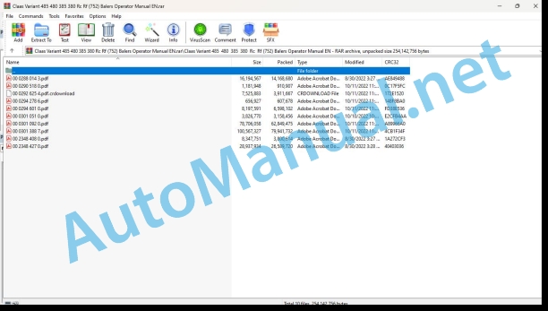
File List:
00 0288 014 3.pdf
00 0290 518 0.pdf
00 0292 625 4.pdf.crdownload
00 0294 278 6.pdf
00 0294 601 0.pdf
00 0301 051 0.pdf
00 0301 092 0.pdf
00 0301 388 7.pdf
00 2348 408 0.pdf
00 2348 427 0.pdf
00 0288 014 3.pdf:
EASY on board app
Table of contents
1 Introduction
1.1 General information
1.1.1 Validity of the manual
1.1.2 Information about this Operator’s Manual
1.1.3 Symbols and notes
1.1.4 Qualified specialist workshop
1.1.5 Maintenance notes
1.1.6 Notes on warranty
1.1.7 Spare parts and technical questions
1.1.8 Technical requirements
1.2 Intended use
1.2.1 Intended use
1.2.2 Reasonably foreseeable misuse
2.1 Identifying warnings
2.1.1 Hazard signs
2.1.2 Signal word
2.2 Safety rules
2.2.1 Meaning of Operator’s Manual
2.2.2 Requirements made on all persons working with the product
2.2.3 Hazard areas
2.2.4 Check interactions with self-propelled machines / tractors and implements
2.2.5 Structural changes
2.2.6 Optional equipment and spare parts
2.2.7 Technical status
2.2.8 Hazard caused by damage to the product
2.2.9 Visibility of work area
2.2.10 Glare and reflections
2.2.11 Unintentional triggering of functions
2.2.12 Hazards caused by signal tones
2.2.13 Unauthorised use
2.2.14 Use of mobile terminal outside the cab
2.2.15 Follow the safety instructions
2.2.16 Respecting technical limit values
2.2.17 Preparing the product for road travel
2.2.18 Hazards when driving on the road and on the field
2.2.19 Hazards when driving on the road with an ISOBUS implement
2.2.20 Switching off the mobile terminal while driving
2.2.21 Hazards from disturbance of WLAN environment
2.2.22 Hazards from covering up the App
2.2.23 Hazards caused by malfunctions of the app
2.2.24 Raised machine parts and loads
3 Product description
3.1 Overview and method of operation
3.1.1 Overview of CWI
3.1.2 Functions of CWI
3.2 Identification plates and identification numbers
3.2.1 CWI identification plate
3.3 Information on the product
3.3.1 Factory settings
3.3.2 Software and hardware version
3.3.3 Seal on the CWI
4 Operating and display elements
4.1 CLAAS Wireless Interface (CWI)
4.1.1 CWI operating elements
4.2 CWI Setup App
4.2.1 Overview of screen
4.2.2 Buttons
4.2.3
4.2.4
4.2.5
5 Technical specifications
5.1 CLAAS Wireless Interface (CWI)
5.1.1 Specification
6 Preparing the product
6.1 Installing the product
6.1.1 Installing the CWI Setup app
6.1.2 Installing the EASY on board app
6.1.3 Connecting the tablet
7 Operation
7.1 Initial operation
7.1.1 Establishing the WLAN connection for the first time
7.1.2 Changing factory settings
7.1.3 Establishing the WLAN connection
7.2 CWI Setup App
7.2.1 Calling up menus
7.2.2 Establishing a secure data connection
7.2.3 Deleting a secure data connection
7.2.4 Displaying the software version
7.3 CWI Setup – Settings
7.3.1 Changing settings
7.3.2 Switching LEDs on and off
7.4 CWI setup – Advanced settings
7.4.1 Deleting the connection partner in CWI
7.4.2 Deleting the connection partner on the tablet
7.4.3 Resetting the CWI to factory settings
7.4.4 Resetting the tablet to factory settings
7.4.5 Switching the CAN filter on and off
7.5 EASY on board App
7.5.1 Launching Operator’s Manual
8 Faults and remedies
8.1 Overview of problems
8.1.1 CWI faults
8.1.2 Fault message: USB charging connection was disconnected
8.1.3 Fault message: Tablet outside WLAN reception area
8.1.4 Fault message: Screen locked
9 Maintenance
9.1 Maintenance schedules
9.1.1 Daily
9.2 Tablet
9.2.1 Cleaning the tablet
9.2.2 Downloading software updates
9.2.3 Updating the operating system
10 Putting out of operation and disposal
10.1 General information
10.1.1 Decommissioning and disposal
11 EC declaration of conformity
11.1 CLAAS Wireless Interface (CWI)
11.1.1 EU Declaration of conformity
12 Technical terms and abbreviations
12.1 Terms and explanations
12.1.1 Abbreviations
12.1.2 Technical terms
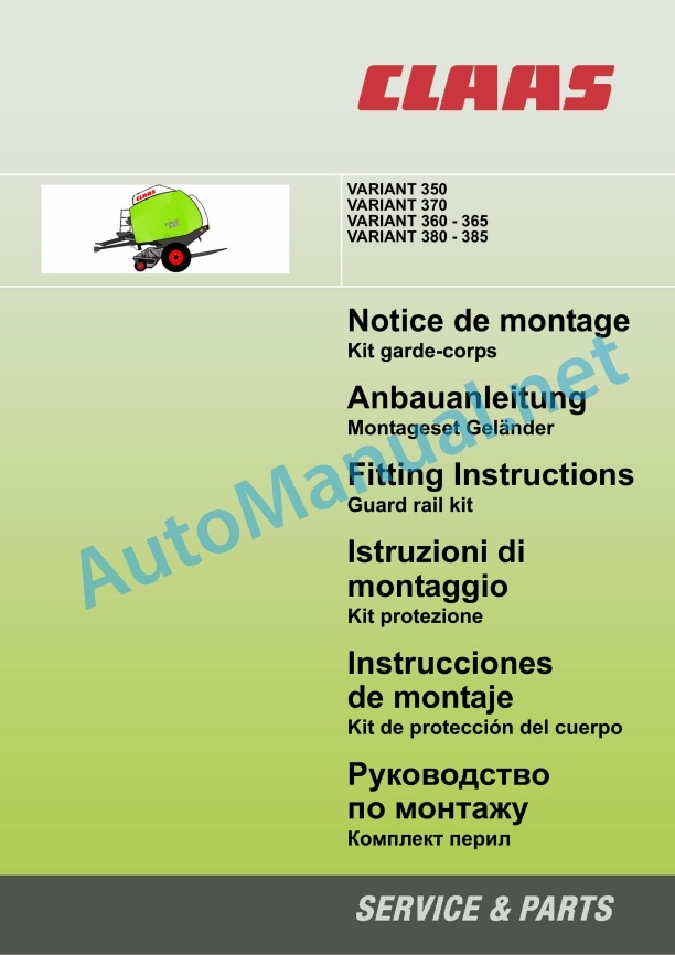
00 0290 518 0.pdf:
1 Introduction
1.1 Generalities
1.2 Machines to equip
2 Safety instructions
2.1 Important
2.1.1 Generalities
2.1.2 Use according to destination
2.2 Safety instructions
2.2.1 Characterization of indications on the dangers
2.2.2 General safety and accident prevention instructions
2.2.3 Parking the machine
3 Lot of pieces
3.1 VARIANT 3XX – 00 0857 722 0
3.1.1 Garde-corps et visserie
4 Montage du garde-corps
4.1 Description
4.1.1 Press security
4.2 Press preparation
4.2.1 Moving the hydraulic brake flexible support (depending on equipment)
4.2.2 Drilling the fixing holes
4.3 Mise en place du garde-corps
1 Introduction
1.1 General
1.2 Auszurustende Maschinen
2 Sicherheitsvorschriften
2.1 Important
2.1.1 General
2.1.2 Benutzung gemäß Zweckbestimmung
2.2 Sicherheitsvorschriften
2.2.1 Kennzeichnung der Gefahrenhinweise
2.2.2 Allgemeine Vorschriften zur Sicherheit und Accidentverhütung
2.2.3 Parking the machine
3 parts list
3.1 VARIANT 3XX – 00 0857 722 0
3.1.1 Railing and fastening material
4 Montage des Geländers
4.1 Description
4.1.1 Sichern der Presse
4.2 Vorbereiten der Presse
4.2.1 Verlegen des Halters für die hydraulic Bremsleitung (je nach Ausrüstung)
4.2.2 Durchführen der Befestigungsbohrungen
4.3 Installation of Railings
1 Introduction
1.1 General points
1.2 Machines that can be fitted
2 Safety advice
2.1 Important
2.1.1 General points
2.1.2 Use in accordance with original specifications
2.2 Safety instructions
2.2.1 Definition of hazard information
2.2.2 General safety and accident prevention advice
2.2.3 Parking the machine
3 parts kit
3.1 VARIANT 3XX – 00 0857 722 0
3.rd rail and bolts
4 Fitting the guard rail
4.1 Description
4.1.1 Securing the baler
4.2 Preparing the baler
4.2.1 Moving the hydraulic brake hose support (depending on equipment)
4.2.2 Drilling the mounting holes
4.3 Fitting the guard rail
1 Introduction
1.1 Generality
1.2 Equipment machine
2 Safety instructions
2.1 Important
2.1.1 Generality
2.1.2 Use as intended
2.2 Safety instructions
2.2.1 Characterization of the indications relative to danger
2.2.2 General safety and incident prevention instructions
2.2.3 Parking the machine
3 Lotto di pezzi
3.1 VARIANT 3XX – 00 0857 722 0
3.1.1 Protection and fittings
4 Installation of the protection
4.1 Description
4.1.1 Rush security
4.2 Press preparation
4.2.1 Displacement of the hydraulic brake hose support (depending on equipment)
4.2.2 Execution of the fixing forum
4.3 Installation of the protection
1 Introduction
1.1 General information
1.2 Applicable machines
2 Safety rules
2.1 Important
2.1.1 General information
2.1.2 Use according to the application
2.2 Security rules
2.2.1 Symbols applicable to danger indications
2.2.2 General safety and accident prevention rules
2.2.3 Fixing the machine
3 Lot of pieces
3.1 VARIANT 3XX – 00 0857 722 0
3.1.1 Body protection and screws
4 Assembling the body protection
4.1 Description
4.1.1 Fixation of the press
4.2 Preparation of the press
4.2.1 Displacement of the hydraulic brake flexible support (depending on the equipment)
4.2.2 Drilling of the fixing holes
4.3 Placement of body protection
1 Ââåäåíèå
1.1 Îáùèå ñâåäåíèØ
1.2 Îáî²óäóåìûå ìàøèíû
2 ÓêàçàíèØ ïî ìå²àì áåçîïàñíîñòè
2.1.1 Îáùèå ñâåäåíèØ
2.1.2 Èñïîëüçîâàíèå ïî íàçíà÷åíè
2.2 ÓêàçàíèØ ïî ìå²àì áåçîïàñíîñòè
2.2.1 Âûäåëåíèå óêàçàíèé íà îïàñíîñòè
2.2.2 Îáùèå óêàçàíèØ t??
4 ?????? ????
4.1 ????????
4.1.1 ϲ???????? ????-????????? ? ?????????? ?????????
4.2 ?????????? ????-?????????
4.2.1 ?????????? ???? ?????? ????????????? ???????? ??????? (? ??????????? ?? ???????????)
4.2.2 ???????? ???????? ????????
4.3 Disclaimer
00 0292 625 4.pdf.crdownload:
COMMUNICATOR II
Table of contents
1 Introduction
1.1 Notes on the manual
1.1.1 Validity of manual
1.1.2 Information about this Operator’s Manual
1.1.3 Symbols and notes
1.1.4 Optional equipment
1.1.5 Qualified specialist workshop
1.1.6 Maintenance notes
1.1.7 Notes on warranty
1.1.8 Spare parts and technical questions
1.2 Intended use
1.2.1 Intended use
1.2.2 Reasonably foreseeable misuse
2.1 Identifying warnings
2.1.1 Hazard signs
2.1.2 Signal word
2.2 Safety rules
2.2.1 Meaning of Operator’s Manual
2.2.2 Requirements made on all persons working with the product
2.2.3 Hazard areas
Hazard areas
2.2.4 Interaction between the control terminal and the machine or tractor
2.2.5 Structural changes
2.2.6 Optional equipment and spare parts
2.2.7 Technical status
2.2.8 Danger from damage to the machine
2.2.9 Complying with technical limit values
2.2.10 Preparing the product for road travel
2.2.11 Hazards when driving on the road and in the field
2.2.12 Hazards when driving on the road with an ISOBUS implement
2.2.13 Switching off the terminal while driving
2.2.14 Electrocution by electrical system
2.2.15 Only carry out work on the machine when it is stopped
2.2.16 Maintenance operations and repair work
2.2.17 Raised machine parts and loads
2.2.18 Welding work prohibited
3 Product description
3.1 Overview and method of operation
3.1.1 Overview of COMMUNICATOR II
3.1.2 Function of COMMUNICATOR II
3.2 Identification plates and identification numbers
3.2.1 Identification plate of COMMUNICATOR II
4 Operating and display elements
4.1 COMMUNICATOR II
4.1.1 Terminal
4.1.2 Terminal program
4.2 Universal terminal menu structure (service)
4.2.1 Main menu of universal terminal
4.2.2
4.2.3
4.2.4
4.2.5
4.3 Job processing (task) menu structure
4.3.1 Job processing main menu
4.3.2
4.3.3
4.3.4
4.3.5
4.3.6
5 Technical specifications
5.1 COMMUNICATOR II
5.1.1 Specification
6 Preparing the product
6.1 Switching off and securing the machine
6.1.1 Shut down and secure the machine
7 Operation
7.1 Switching COMMUNICATOR II on/off
7.1.1 Switching COMMUNICATOR II on
7.1.2 Selecting the application
7.1.3 Switching off COMMUNICATOR II
7.2 Programmable keys
7.2.1 Displaying the key assignment
7.2.2 Creating a key assignment
Step 1: Selecting the control and the key
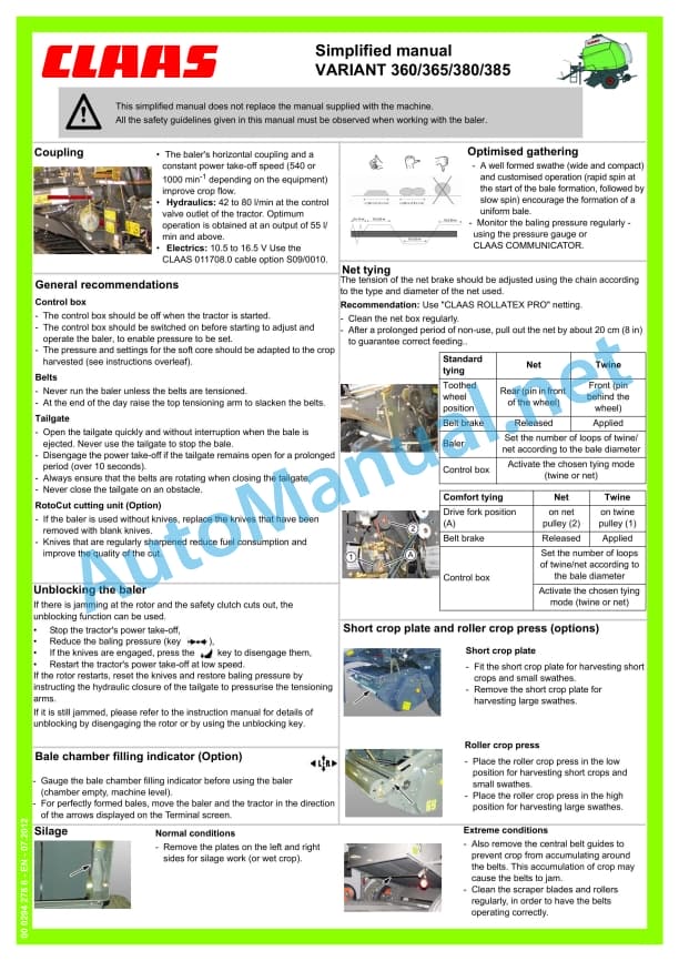
00 0294 278 6.pdf:
Short crop plate
Roller crop press
Short crop plate and roller crop press (options)
Settings (recommended values)
Optimised gathering
General recommendations
Unblocking the baler
Bale chamber filling indicator (Option)
00 0294 601 0.pdf:
FR_0100.pdf
Assembly and use instructions
“Linen – short linen” kit and “Very short linen” kit
FR_0001.pdf
Introduction
FR_0002_V2.pdf
Introduction
FR_0101.pdf
Safety instructions
FR_0102b_V2.pdf
Characterization of hazard indications
General safety and accident prevention instructions
Machine parking
Use as intended
FR_0200.pdf
Installation instructions
Linen and short linen kit
FR_0508_V2.pdf
Use of the press for other crops
Pressing chamber
FR_0507_V2.pdf
Use for pressing very short linen
Preparing the pressing chamber
Mounting the slides on the wall – Variant 360
Mounting the slides on the wall – Variant 380
Installation of the very short linen sheet
Fixing the very short linen sheet
“Moveable” slide adjustment
Harvesting on non-stony ground
Harvesting on stony ground
FR_0506_V2.pdf
Use for pressing short linen
Preparing the pressing chamber
Mounting the slides on the wall – Variant 360
Mounting the slides on the wall – Variant 380llation of the short linen sheet
Fixing the short linen sheet
“Moveable” slide adjustment
Harvesting on non-stony ground
Harvesting on stony ground
FR_0505_V2.pdf
Use for pressing linen
Harvesting on non-stony ground
Harvesting on stony ground
FR_0504_V2.pdf
Before use
Linen kit front frame adjustment
Center wheel height
Height of forage guides
Setting the proximity sensor
Ski height
Press adjustment
Number of turns of string
“Linen” twine guides
Flax harvest
Harvesting short flax and very short flax
Setting up the string
Setting using the Terminal
Pressing pressure adjustment
Bale diameter adjustment
Binding adjustment
FR_0503_V2.pdf
Principle and operation
Pressing direction
Pressing pressure
Tying flax stems
Forward speed and slick ratio
FR_0502_V2.pdf
Introduction
FR_0500.pdf
Instructions for use
FR_0404_V2.pdf
Preparation of the “very short line Variant 360
Drilling the pressing chamber
Pre-assembly of the “very short linen” kit
Variant 380
Drilling the pressing chamber
Pre-assembly of the “very short linen” kit
FR_0402_V2.pdf
Parts set (0844 809.0)
FR_0401_V2.pdf
Introduction
FR_0400.pdf
Installation instructions
Very short linen kit
FR_0210_V2.pdf
Module configuration for linen
Verification of information
Fixing the cable to the chassis
Setting the proximity sensor
Installing the cover
FR_0209_V2.pdf
Twine and knife guides
Fitting the “Linen” twine guides
Assembly of the “Lin” knife
Disassembly of the original knife
Assembly of the “Lin” knife
FR_0208_V2.pdf
Preparation of the “Short linen” kit
Variant 360
Drilling the pressing chamber
Pre-assembly of the “short linen” kit
Variant 380
Drilling the pressing chamber
Pre-assembly of the “short linen” kit
FR_0207_V2.pdf
Assembly of the linen kit
Fixingpress
Mounting the ski on the frame
Attaching the hook to the machine
FR_0206_V2.pdf
Pre-assembly of the linen kit
Mounting the wheel on the frame
Mounting the forage guides on the frame
Mounting the proximity sensor
Lubricator
FR_0205_V2.pdf
Preparing the pick-up
Dismantling the packer
Removing the pick-up protective cover
Assembly of the “Linen Kit” chain wheel
Removing the centering screws
Reassembly of the pickup housing
Removing Pickup Teeth
Preparing the walls of the pick-up
FR_0204_V2.pdf
Reduction in the number of belts
Relaxing the belts
Belt cutting
Belt length adjustment
Stapling the belts
FR_0202_V2.pdf
Parts set (0844 801.0)
FR_0201_V2.pdf
Introduction
FR_0509_V2.pdf
Maintenance
Lubricator
RU_0100.pdf
Èíñò²óêöèØ ïî ñáî²êå è Æêñïëóàòàöèè
Êîìïëåêò «ëåí – êî²îòêèé ëåí» è êîìïëåêò «î÷åíü êî²îòêèé ëåí»
RU_0001.pdf
RU_0002_V2.pdf
R ϲåññ-êàìå²à
Åëåêò²è÷åñêèé òîê
RU_0507_V2.pdf
Èñïîëüçîâàíèå äëØ ï²åññîâêè êî²îòêîãî ëüíà
Îáùèå ñâåäåíèØ
Ïîäãîòîâêà ï²åññ-êàìå²û
Ìîíòàæ íàï²àâëØ ùèõ íà ñòåíêó – Variant 360
Ìîíòàæ íàï²àâëØ ùèõ íà ñòåíêó – Variant 280
Óñòàíîâêà ñâà²íîãî ëèñòà «Î÷åíü êî²îòêèé ëåí»
ÔèêñàöèØ ñâà²íîãî ëèñòà «Î÷åíü êî²îòêèé ëåí»
Ãåãóëè²îâêà «ïîäâèæíîé» íàï²àâëØ ùåé
Óáî²êà íà íåêàìåíèñòîé ïî÷âå
Óáî²êà íà êàìåíèñòîé ïî÷âå
RU_0506_V2.pdf
Èñïîëüçîâàíèå äëØ ï²åññîâêè êî²îòêîãî ëüíà
Îáùèå ñâåäåíèØ
Ïîäãîòîâêà ï²åññ-êàìå²û
Ìîíòàæ íàï²àâëØ ùèõ íà ñòåíêó – Variant 360
Ìf
Ïîäãîòîâêà ê èñïîëüçîâàíè
Íàëàäêà ïå²åäíåé ²àìû êîìïëåêòà «Ëåí»
Âûñîòà öåíò²àëüíîãî êîëåñà
Âûñîòà íàï²àâëØ ùèõ ôó²àæà
Íàñò²îéêà äåòåêòî²à ï²èáëèæåíèØ
Âûñîòà ëûæè
Íàëàäêà ï²åññà
°èñëî îáî²îòîâ áå÷åâêè
Íàï²àâëØ ùèå áå÷åâêè «Ëåí»
Óáî²êà ëüíà
Óáî²êà êî²îòêîãî è î÷åíü êî²îòêîãî ëüíà
Çàï²àâêà áå÷åâêè
Ãåãóëè²îâêà ñ èñïîëüçîâàíèåì òå²ìèíàëà
Ãåãóëè²îâêà äàâëåíèØ ï²åññîâàíèØ
Ãåãóëè²îâêà äèàìåò²à ò êîâ
Ãåãóëè²îâêà îáâØçêè
RU_0503_V2.pdf
ϲèíöèï è ôóíêöèîíè²îâàíèå
Ñêî²îñòü îòáî²à ìîùíîñòè
Íàï²àâëåíèå ï??????? ????
RU_0402_V2.pdf
????? ??????? (0844 809.0)
RU_0401_V2.pdf
RU_0400.pdf
????????? ?? ?????
???????? ?????? ??????? ????
RU_0210_V2.pdf
?????????????????
???????? ?????? ?? ????? ????
ϲ????? ??????
ʲ??????? ?????? ?? ????
?????????? ?????????????? ???????
????????? ????????? ?????
RU_0209_V2.pdf
??????? ??? ??????? ? ???
?????? ??????? ??? ??????? ????????? ?????
?????? ???? ?????
???????? ??????????? ????
?????? ???? ?????
RU_0208_V2.pdf
?????????? ????????? ???????? ????
Variant 360
???????? ???????? ? ????? ??????????
ϲ???????????? ?????? ????????? ???????? ????
Variant 380
???????? ???????? ? ????? ??????????
ϲ???????????? ?????? ????????? ???????? ????
RU_0207_V2.pdf
????? ????????? ?????
ʲ??????? ????????????? ???? ? ?????
????????? ???? ?? ????
ʲ??????? ??????? ?? ??????
RU_0206_V2.pdf
ϲ???????????? ????? ????????? ?????
????????? ?????? ?? ????
Óñòàíîâêà íàï²àâëØ ùèõ ôó²àæà íà ²àìó
Óñòàíîâêà äåòåêòî²à ï²èáëèæåíèØ
Ñìàçî÷íîå îòâå²ñòèå
RU_0205_V2.pdf
Ïîäãîòîâêà ï²åññ-ïîäáî²ùèêà
Äåìîíòàæ ò²àìáîâùèêà
Äåìîíòàæ êà²òå²à çàùèòû ï²åññ-ïîäáî²ùèêà
Ìîíòàæ çâåçäî÷êè èç íàáî²à «Ëåí»
Äåìîíòàæ öåíò²îâî÷íûõ âèíòîâ
Óñòàíîâêà êà²òå²à ï²åññ-ïîäáî²ùèêà
Äåìîíòàæ ïàëüöåâ ñ ï²åññ-ïîäáî²ùèêà
Ïîäãîòîâêà áî²òîâ ï²åññ-ïîäáî²ùèêà
RU_0204_V2.pdf
Óìåíüøåíèå ÷èñëà ï²èâîäíûõ ²åìíåé
Îñëàáëåíèå ²åìíåé
Îá²åçêà ²åìíåé
Ãåãóëè²îâêà äëèíû ²åìíåé
Ñê²åïëåíèå ²åìíØ
RU_0202_V2.pdf
Ïà²òèØ äåòàëåé (0843 001.0)
RU_0201_V2.pdf
RU_02df
Parts set (0844 801.0)
FR_0204_V2.pdf
Reduction in the number of belts
Relaxing the belts
Belt cutting
Belt length adjustment
Stapling the belts
FR_0205_V2.pdf
Preparing the pick-up
Dismantling the packer
Removing the pick-up protective cover
Assembly of the “Linen Kit” chain wheel
Removing the centering screws
Reassembly of the pickup housing
Removing Pickup Teeth
Preparing the walls of the pick-up
FR_0206_V2.pdf
Pre-assembly of the linen kit
Mounting the wheel on the frame
Mounting the forage guides on the frame
Mounting the proximity sensor
Lubricator
FR_0207_V2.pdf
Assembly of the linen kit
Fixing the pre-assembled frame on the press
Mounting the ski on the frame
Attaching the hook to the machine
FR_0208_V2.pdf
Preparation of the “Short linen” kit
Variant 360
Drilling the pressing chamber
Pre-assembly of the “short linen” kit
Variant 380
Drilling the pressing chamber
Pre-assemshort linen” kit
FR_0209_V2.pdf
Twine and knife guides
Fitting the “Linen” twine guides
Assembly of the “Lin” knife
Disassembly of the original knife
Assembly of the “Lin” knife
FR_0210_V2.pdf
Module configuration for linen
Verification of information
Fixing the cable to the chassis
Setting the proximity sensor
Installing the cover
FR_0400.pdf
Installation instructions
Very short linen kit
FR_0400.pdf
Installation instructions
Very short linen kit
FR_0401_V2.pdf
Introduction
FR_0402_V2.pdf
Parts set (0844 809.0)
FR_0404_V2.pdf
Preparation of the “very short linen” kit
Variant 360
Drilling the pressing chamber
Pre-assembly of the “very short linen” kit
Variant 380
Drilling the pressing chamber
Pre-assembly of the “very short linen” kit
FR_0500.pdf
Instructions for use
FR_0502_V2.pdf
Introduction
FR_0503_V2.pdf
Principle and operation
Pressing direction
Pressing pressure
Tyinpeed and slick ratio
FR_0504_V2.pdf
Before use
Linen kit front frame adjustment
Center wheel height
Height of forage guides
Setting the proximity sensor
Ski height
Press adjustment
Number of turns of string
“Linen” twine guides
Flax harvest
Harvesting short flax and very short flax
Setting up the string
Setting using the Terminal
Pressing pressure adjustment
Bale diameter adjustment
Binding adjustment
FR_0505_V2.pdf
Use for pressing linen
Harvesting on non-stony ground
Harvesting on stony ground
FR_0506_V2.pdf
Use for pressing short linen
Preparing the pressing chamber
Mounting the slides on the wall – Variant 360
Mounting the slides on the wall – Variant 380
Installation of the short linen sheet
Fixing the short linen sheet
“Moveable” slide adjustment
Harvesting on non-stony ground
Harvesting on stony ground
FR_0507_V2.pdf
Use for pressing very short liPreparing the pressing chamber
Mounting the slides on the wall – Variant 360
Mounting the slides on the wall – Variant 380
Installation of the very short linen sheet
Fixing the very short linen sheet
“Moveable” slide adjustment
Harvesting on non-stony ground
Harvesting on stony ground
FR_0508_V2.pdf
Use of the press for other crops
Pressing chamber
FR_0509_V2.pdf
Maintenance
Lubricator
RU_0100.pdf
Èíñò²óêöèØ ïî ñáî²êå è Æêñïëóàòàöèè
Êîìïëåêò «ëåí – êî²îòêèé ëåí» è êîìïëåêò «î÷åíü êî²îòêèé ëåí»
RU_0001.pdf
RU_0002_V2.pdf
RU_0101.pdf
ÓêàçàíèØ ïî òåõíèêå áåçîïàñíîñòè
RU_0102b_V2.pdf
ÂàæíàØ èíôî²ìàöèØ
Îïèñàíèå ï²åäóï²åäèòåëüíûõ çíàêîâ
Îáùå óêàçàíèØ ïî òåõíèêå áåçîïàñíîñòè è ï²åäîòâ²àùåíè íåñ÷àñòíûõ ñëó÷àåâ
ÑòîØíêà ìàøi
Îá²åçêà ²åìíåé
Ãåãóëè²îâêà äëèíû ²åìíåé
Ñê²åïëåíèå ²åìíØ
RU_0205_V2.pdf
Ïîäãîòîâêà ï²åññ-ïîäáî²ùèêà
Äåìîíòàæ ò²àìáîâùèêà
Äåìîíòàæ êà²òå²à çàùèòû ï²åññ-ïîäáî²ùèêà
Ìîíòàæ çâåçäî÷êè èç íàáî²à «Ëåí»
Äåìîíòàæ öåíò²îâî÷íûõ âèíòîâ
Óñòàíîâêà êà²òå²à ï²åññ-ïîäáî²ùèêà
Äåìîíòàæ ïàëüöåâ ñ ï²åññ-ïîäáî²ùèêà
Ïîäãîòîâêà áî²òîâ ï²åññ-ïîäáî²ùèêà
RU_0206_V2.pdf
ϲåäâà²èòåëüíàØ ñáî²êà êîìïëåêòà «Ëåí»
Óñòàíîâêà êîëåñà íà ²àìó
Óñòàíîâêà íàï²àâëØ ùèõ ôó²àæà íà ²àìó
Óñòàíîâêà äåòåêòî²à ï²èáëèæåíèØ
Ñìàçî÷íîå îòâå²ñòèå
RU_0207_V2.pdf
Ñáî²êà êîìïëåêòà «iong>
PROFI CAM 3
Table of contents
1 Introduction
1.1 Notes on the manual
1.1.1 Validity of manual
1.1.2 Information about this Operator’s Manual
1.1.3 Symbols and notes
1.1.4 Optional equipment
1.1.5 Qualified specialist workshop
1.1.6 Maintenance information
1.1.7 Warranty notes
1.1.8 Spare parts and technical questions
1.2 Intended use
1.2.1 Intended use
1.2.2 Reasonably foreseeable misuse
2.1 Identifying warnings
2.1.1 Hazard signs
2.1.2 Signal word
2.2 Safety rules
2.2.1 Meaning of Operator’s Manual
2.2.2 Observing safety decals and warnings
2.2.3 Optional equipment and spare parts
3 Product description
3.1 Overview and method of operation
3.1.1 How the PROFI CAM works
3.2 Identification plates and identification number
3.2.1 Position of identification plates
3.2.2 Explanation of PROFI CAM identification plate
3.3 Information on the product
3.3.1 CE marking
4 Operating and control elements
4.1 Camera system
4.1.1 Camera system monitor
4.2 Menu structure
4.2.1 Main menu
4.2.2
4.2.3
4.2.4
4.2.5
4.2.6
5 Technical specifications
5.1 PROFI CAM
5.1.1 Monitor
5.1.2 Camera
5.1.3 Switch box
5.1.4 Degree of protection against foreign bodies and water
6 Preparing the product
6.1 Shutting down and securing the machine
6.1.1 Switching off and securing the machine
6.2 Prior to operation
6.2.1 Carry out prior to operation
6.2.2 Installing the sun protection
6.2.3 Aligning the camera
6.2.4 Connecting the camera electrics
7 Operation
7.1 Monitor
7.1.1 Switching on the monitor
7.1.2 Calling up the menu
7.1.3 Setting a menu item
7.1.4 Setting the image orientation
7.1.5 Setting automatic screen darkening
7.1.6 Image mirroring
7.1.7 Setting the trigger view
7.1.8 Setting the follow-up time for trigger view
7.1.9 Setting the display mode
7.1.10 Activating/deactivating a display mode
8 Faults and remedies
8.1 Electrical and electronic system
8.1.1 Overview of problems on PROFI CAM camera system
8.1.2 Replacing the switch box fuse
9 Maintenance
9.1 Maintenance intervals
9.1.1 Every 10 operating hours or daily
9.2 Camera system
9.2.1 Checking the camera system for dirt
9.2.2 Cleaning the camera
9.2.3 Cleaning the switch box
9.2.4 Cleaning the monitor
10 Placing out of operation and disposal
10.1 General Information
10.1.1 Putting out of operation and disposal
11 Technical terms and abbreviations
11.1 Abbreviations
11.1.1 Units
11.1.2 Abbreviations
11.1.3 Technical terms
00 0301 092 0.pdf:
VARIANT 360 / 360 RotoCutVARIANT 365 RotoCutVARIANT 380 / 380 RotoCutVARIANT 385 RotoCut
Table of contents
1 To this Operator’s Manual
1.1 General information
1.1.1 Manual validity
1.1.2 Using the manual
1.1.3 Symbols and notes
1.1.4 Technical specifications
2.1 General information
2.1.1 General points
2.1.2 Using in line with intended usage
2.1.3 Reasonably foreseeable improper usage
2.1.4 Driving on the road
2.1.5 Definition of hazard information
2.1.6 Safety advice
2.1.7 Accident prevention
2.1.8 Waste disposal
2.1.9 Residual risks
2.2 Safety decals
2.2.1 Description
2.2.2 Location of safety stickers
2.3 Safety equipment
2.3.1 Indicator lights
2.3.2 Reflective equipment
2.3.3 Jack stand
2.3.4 Chocks
2.3.5 Retaining cable (machine not equipped with brake and which can be used in France)
2.3.6 Parking brake
2.3.7 Locking the tailgate
2.3.8 Locking the pick-up
2.3.9 Extinguisher
2.3.10 Main gearbox output protection, without twine tying
3 Machine description
3.1 Existing models
3.1.1 Machine description
3.2 Overview and functions
3.2.1 Left-hand side
3.2.2 Right-hand side
3.2.3 Roller identification
3.3 Working and service areas
3.3.1 General points
John Deere Parts Catalog PDF
John Deere Harvesters 8500 and 8700 Parts Catalog CPCQ24910 Spanish
John Deere Repair Technical Manual PDF
John Deere 18-Speed PST Repair Manual Component Technical Manual CTM168 10DEC07
John Deere Repair Technical Manual PDF
John Deere Repair Technical Manual PDF
John Deere Transmission Control Unit Component Technical Manual CTM157 15JUL05
John Deere Repair Technical Manual PDF
John Deere Repair Technical Manual PDF
John Deere Repair Technical Manual PDF
John Deere POWERTECH E 4.5 and 6.8 L Diesel Engines TECHNICAL MANUAL 25JAN08
John Deere Repair Technical Manual PDF

