Claas Vario 1380-1080 (823) Combines Technical System ES
$150.00
- Model: Vario 1380-1080 (823) Combines
- Type Of Manual: Technical System
- Language: ES
- Format: PDF(s)
- Size: 25.6 MB
File List:
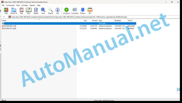
00 0305 820 1.pdf
00 0305 977 0.pdf
00 0305 820 1.pdf:
Technical systems
Introduction
Information regarding the instruction manual
Manual validity
Information regarding this technical systems manual
Using the manual
Structuring with construction group structure
Search and find
Direction signs
Security
Recognize warning signs
Danger symbols
Safety instructions
Graphic danger symbols and warning indications
Requirements for technical personnel
Children in danger
Machine danger zones
Accompanying instructor during work
Risk of injury due to rotating shafts
Construction modifications to the machine
Optional equipment and spare parts
Control of the machine running
Technical status
Comply with technical limit values
Danger from machine parts during coasting
Keep protective devices operational
Personal protective equipment
Wear appropriate clothing
Remove dirt and loose objects
Park the machine safely
Unsuitable consumables
Safe handling of consumables and auxiliary materials
Environmental protection and waste disposal
Keep the cabin free of chemicals
Fire prevention
Lethal electrical shock due to overhead power lines and lightning strikes
Current discharge through the electrical installation
Noise can cause health damage
Prestressed machine parts
Liquids under pressure
Air under presure
Toxic exhaust gases
Hot surfaces
Safe ascent and descent
Only work on the stopped machine
Dangers in repair work
Machine parts and lifted loads
Danger from welding work
Check and charge the battery
Emergency Preparations
CCN Explanation
CCN (CLAAS Component Number)
General indications
Electrical regulations
Hydraulic regulations
CCN (CLAAS Component Number)
09 Hydraulics
0920 Valves
Reel/Table/Feed Auger Adjustment Control Valve Block
0980 Hydraulic connection diagram
VARIO head hydraulic installation – type 823
Cutting mechanism V1080-V1380 (type 823) – SCM 01 – reel drive
Cutting mechanism V1080-V1380 (type 823) – SCM 02 – feed auger adjustment
Cutting mechanism V1080-V1380 (type 823) – SCM 03 – cutting table adjustment
Cutting mechanism V1080-V1380 (type 823) – SCM 04 – reel adjustment
10 Install. electrical/electronic
1012 Modules / sensors
A130 module – head – TYPE 823 VARIO
Denominations
Denominations
Module A176 – head expansion – TYPE 823 VARIO
Denominations
Denominations
Module A219 – head lighting – TYPE 823 VARIO
Denominations
Denominations
1015 Cable sets
Multiple coupling
Multiple head coupling
Function Description
1080 Electrical connection diagram
Head connection diagrams – VARIO cutting mechanism (type 823)
ATT 01 – Multiple coupling
Denominations
ATT 02 – Module voltage supply / CAN-Bus
Denominations
ATT 03 – Windlass
Denominations
ATT 04 – Feed auger
Denominations
ATT 05 – Table adjustment
Denominations
ATT 07 – AUTO CONTOUR
Denominations
ATT 08 – Autopilot
Denominations
ATT 09 – Flash lights
Denominations
ATT 10- Lighting
Denominations
ATT 11 – Summary of modules
Denominations
20 Reception of the harvest
2010 Cutting table
VARIO cutting table adjustment
Table of measured values
Description of the cutting table adjustment function
Hydraulic installation: adjustment of the cutting table
2015 Pinwheel
Raise/lower the reel, automatic reel height
Table of measured values
Function description, reel regulation
Forward/backward windlass
Table of measured values
Function description, reel regulation
21 Power set
2140 Feed auger
Raise/lower feed auger center
Table of measured values
Feed auger adjustment function description
Location of components
Hydraulic installation
2000 Pump/motor
3000 Hydraulic Cylinders
4000 Choke / calibrated orifice
Electrical installation
To Terminal/modules
B Sensors
and lighting
U Switch – external operation
X Pluggable connections
and electromagnetic coils
00 0305 977 0.pdf:
Technical systems
Introduction
Information regarding the instruction manual
Manual validity
Information regarding this technical systems manual
Using the manual
Structuring with construction group structure
Search and find
Direction signs
Security
Recognize warning signs
Danger symbols
Safety instructions
Graphic danger symbols and warning indications
Requirements for technical personnel
Children in danger
Machine danger zones
Accompanying instructor during work
Risk of injury due to rotating shafts
Construction modifications to the machine
Optional equipment and spare parts
Control of the machine running
Technical status
Comply with technical limit values
Danger from machine parts during coasting
Keep protective devices operational
Personal protective equipment
Wear appropriate clothing
Remove dirt and loose objects
Park the machine safely
Unsuitable consumables
Safe handling of consumables and auxiliary materials
Environmental protection and waste disposal
Keep the cabin free of chemicals
Fire prevention
Lethal electrical shock due to overhead power lines and lightning strikes
Current discharge through the electrical installation
Noise can cause health damage
Prestressed machine parts
Liquids under pressure
Air under presure
Toxic exhaust gases
Hot surfaces
Safe ascent and descent
Only work on the stopped machine
Dangers in repair work
Machine parts and lifted loads
Danger from welding work
Check and charge the battery
Emergency Preparations
CCN Explanation
CCN (CLAAS Component Number)
General indications
Electrical regulations
Hydraulic regulations
CCN (CLAAS Component Number)
09 Hydraulics
0920 Valves
Reel/Table/Feed Auger Adjustment Control Valve Block
0980 Hydraulic connection diagram
VARIO head hydraulic installation – type 823
Cutting mechanism V1080-V1380 (type 823) – SCM 01 – reel drive
Cutting mechanism V1080-V1380 (type 823) – SCM 02 – feed auger adjustment
Cutting mechanism V1080-V1380 (type 823) – SCM 03 – cutting table adjustment
Cutting mechanism V1080-V1380 (type 823) – SCM 04 – reel adjustment
10 Install. electrical/electronic
1012 Modules / sensors
A130 module – head – FAM (1/3)
Denominations
Denominations
A130 module – head – FAM (2/3)
Denominations
Denominations
A130 module – head – FAM (3/3)
Denominations
Denominations
1015 Cable sets
Multiple coupling
Multiple head coupling
Function Description
1080 Electrical connection diagram
Head connection diagrams – VARIO cutting mechanism (type 823)
ATT 01 – Multiple coupling
Denominations
ATT 02 – Module voltage supply / CAN-Bus
Denominations
ATT 03 – Windlass
Denominations
ATT 04 – Feed auger
Denominations
ATT 05 – Cutting mechanism table adjustment
Denominations
ATT 07 – AUTO CONTOUR
Denominations
ATT 08 – AUTOPILOT
Denominations
ATT 09 – Flash lights
Denominations
ATT 10- Lighting
Denominations
20 Reception of the harvest
2010 Cutting table
VARIO cutting table adjustment
Table of measured values
Description of the cutting table adjustment function
Hydraulic installation: adjustment of the cutting table
2015 Pinwheel
Raise/lower the reel, automatic reel height
Table of measured values
Function description, reel regulation
Forward/backward windlass
Table of measured values
Function description, reel regulation
21 Power set
2140 Feed auger
Raise/lower feed auger center
Table of measured values
Feed auger adjustment function description
Location of components
Hydraulic installation
2000 Pump/motor
3000 Hydraulic Cylinders
4000 Choke / calibrated orifice
Electrical installation
To Terminal/modules
B Sensors
and lighting
U Switch – external operation
X Pluggable connections
and electromagnetic coils
John Deere Repair Technical Manual PDF
John Deere Repair Technical Manual PDF
John Deere Diesel Engines PowerTech 4.5L and 6.8L – Motor Base Technical Manual 07MAY08 Portuguese
John Deere Repair Technical Manual PDF
John Deere Repair Technical Manual PDF
John Deere POWERTECH E 4.5 and 6.8 L Diesel Engines TECHNICAL MANUAL 25JAN08
John Deere Repair Technical Manual PDF
John Deere Repair Technical Manual PDF
John Deere Parts Catalog PDF
John Deere Harvesters 8500 and 8700 Parts Catalog CPCQ24910 Spanish
John Deere Repair Technical Manual PDF
John Deere Transmission Control Unit Component Technical Manual CTM157 15JUL05
John Deere Parts Catalog PDF
John Deere Tractors 7500 Parts Catalog CPCQ26568 30 Jan 02 Portuguese


