Claas Vario 930-500 Cerio 930-560 (528) Combines Operator Manual ES
$50.00
- Model: Vario 930-500 Cerio 930-560 (528) Combines
- Type Of Manual: Operator Manual
- Language: ES
- Format: PDF(s)
- Size: 24.7 MB
File List:
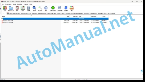
00 0297 292 1.pdf
00 0299 673 7.pdf
00 0297 292 1.pdf:
VARIO 1250 / 1050MAXFLEX 1250 / 1050MAXFLO 1250 / 1050C900 – C450V900 – V540
1. Introduction
1.1 Information on the instruction manual
1.1.1 Validity of the manual
1.1.2 Information on the instruction manual
2 Security
2.1 Recognize warning signs
2.1.1 Danger symbols
2.1.2 Keyword
2.2 Safety instructions
2.2.1 Instruction manual and other sources of information
Meaning of the instruction manual
2.2.2 Invisible laser beam of 1M laser category
2.2.3 Proper machine application
3 Technical data
3.1 LASER PILOT
3.1.1 LASER PILOT
4 Management
4.1 Address
4.1.1 Deploy the LASER PILOT
4.1.2 Adjust the LASER PILOT
Preparing the terrain
Adjust the LASER PILOT to the harvesting material
Adjust the LASER PILOT to the harvesting material
Prepare the adjustment process
Check the LASER PILOT setting
Vertically adjust the LASER PILOT
Control the horizontal preset of the LASER PILOT
Perform horizontal fine adjustment of the LASER PILOT
5 Incident and solution
5.1 Incident summary
5.1.1 LASER PILOT
00 0299 673 7.pdf:
1. Introduction
1.1 Information on the instruction manual
1.1.1 Validity of the manual
1.1.2 Information relating to this instruction manual
1.1.3 Symbols and indications
1.1.4 Optional equipment
1.1.5 Qualified specialized workshop
1.1.6 Maintenance instructions
1.1.7 Information regarding warranty
1.1.8 Spare parts and technical questions
1.2 Proper application of the machine
1.2.1 Proper machine application
1.2.2 Logically foreseeable misuse
2 Security
2.1 Recognize warning signs
2.1.1 Danger symbols
2.1.2 Keyword
2.2 Safety instructions
2.2.1 Meaning of the instruction manual
2.2.2 Observe graphic danger symbols and alarm indications
.2.3 Requirements for all peoplrking with the machine
2.2.4 Danger zones
2.2.5 Position yourself between the machine and the head
2.2.6 Accompanying persons
2.2.7 Attach the machine to a header or transport trailer
2.2.8 Risk of injury due to rotating shafts
2.2.9 Construction changes
2.2.10 Optional equipment and spare parts
2.2.11 Use only after correct commissioning
2.2.12 Technical status
2.2.13 Danger due to machine breakdowns
2.2.14 Keep protective devices operational
2.2.15 Personal protective equipment
2.2.16 Wear appropriate clothing
2.2.17 Remove dirt and loose objects
2.2.18 Prepare the machine for road traffic
2.2.19 Unsuitable consumables
2.2.20 Safe handling of consumables and auxiliary materials
2.2.21 Environmental protection and waste disposal
2.2.22 Electrical shock from electrical equipment
2.2.23 Liquids under pressure
2.2.24 Work only on the stopped machine
2.2.25 Maintenance work and repair work
2.2.26 Machine parts and lifted loads
2.2.27 Danger from welding work
2.3 Safety signage
2.3.1 Structure of graphic hazard symbols
2.3.2 Graphic danger symbols on the head
3 Machine Description
3.1 Summary and operation
3.1.1 Machine overview
3.1.2 Storage of the instruction manual
3.1.3 VARIO operating mode
3.1.4 CERIO operating mode
3.1.5 Mode of operation of overload protections
3.2 Optional machine equipment
3.2.1 External reel tines
3.2.2 CLAAS AUTO CONTOUR probes
3.2.3 Stone collection plate
3.2.4 Drainer
3.2.5 Anti-winding protection
3.2.6 Extension of the exterior dividers
3.2.7 Lighting
3.2.8 Rapeseed separator knives
3.2.9 Rapeseed equipment, transport box
3.3 Identification plates and identification numbers
3.3.1 Head identification plate
3.4 Machine information
3.4.1 Adhesives
4 Control and display instruments
4.1 Cabin and driving position
4.1.1 Control desk
4.2 Head
4.2.1 Control elements
5 Technical data
5.1 VARIO / CERIO
5.1.1 Eligible machines
5.1.2 Dimensions
5.1.3 Weights
5.1.4 Cutting widths
5.1.5 Windlass
5.1.6 Feed auger
5.2 Inputs
5.2.1 Lubricants
5.2.2 Hydraulic oil
6 Preparation of the machine
6.1 Turn off the machine and secure it
6.1.1 Turn off the machine and secure it
6.2 Load the head
6.2.1 Load and tie down the head
6.3 Assemble the head
6.3.1 Assemble the head
6.3.2 Prepare the bolting
6.3.3 Attach the head
6.3.4 Locking the head
6.3.5 Assemble the cardan shaft
6.3.6 Attach the cardan shaft protection chain
6.3.7 Installing the multiple coupling
6.3.8 Remove the support legs
6.3.9 Adjusting the header in the combine on-board information system
6.4 Disassemble the head
6.4.1 Disassemble the head
6.4.2 Assemble the support legs
6.4.3 Dismantling the multiple coupling
6.4.4 Disassemble cardan shaft
6.4.5 Unlock the head
6.4.6 Unhook the head
6.5 Harvest harvest
6.5.1 Place the windlass safety support
6.5.2 Release the safety supports of the windlass
6.5.3 Adjust the position of the cutting mechanism table
6.6 Feed auger
6.6.1 Adapt the scraper strips to the feed channel
6.7 Mowing device
6.7.1 Install the cutter bar protection device
6.7.2 Assemble the rice cutting system*
Control the oppressor
7 Management
7.1 Driving the machine
7.1.1 Prepare for road traffic
7.1.2 Prepare the field trip
7.1.3 Adjust the rest position
7.1.4 Manually adjust the rest position
7.2 Work application
7.2.1 Before use for work
7.2.2 Adjust the working position
7.2.3 Control the collection of harvest material
7.3 Rapeseed harvest
7.3.1 Assemble rapeseed equipment*
7.3.2 Assembling the rapeseed separator blade*
7.3.3 Connect the rapeseed equipment* to the hydraulic system
Left side
Right side
7.4 Cereal harvest
7.4.1 Assemble the cereal equipment
7.4.2 Separate the rapeseed equipment* from the hydraulic system
Left side
Right side
7.4.3 Removing the rapeseed separator blade*
7.5 Feed auger
7.5.1 Adjusting the feed auger scraper strips
7.5.2 Adjust the position of the feeding auger
7.5.3 Adjust the feed auger fingers
7.5.4 Remove the extensions from the auger plate
7.5.5 Assemble the auger plate extensions
7.5.6 Modify the speed of the feeding auger
7.6 Address
7.6.1 Deploy LASER PILOT*
7.6.2 Fold LASER PILOT*
7.7 Electrical and electronic system
7.7.1 Turn lighting on and off*
Manage head lighting
Manage lighting from the cabin
7.8 Harvest harvest
7.8.1 Mounting the crop divider
7.8.2 Dismantle the crop divider
7.8.3 Adjusting the long crop divider
7.8.4 Deploy the long crop divider
7.8.5 Folding the long crop divider
7.8.6 Assemble the outer separator
7.8.7 Remove the outer separator
7.8.8 Assemble the transfer plate
7.8.9 Remove the transfer plate
7.8.10 Adjust the short crop divider
7.8.11 Deploy the short crop divider
7.8.12 Fold the short crop divider
7.8.13 Adjust the position of the cutting mechanism table from the cabin
7.8.14 Adjust the position of the cutting mechanism table in the headstock
7.8.15 Adjust reel tine
7.8.16 Close the opening for cleaning
7.9 Mowing device
7.9.1 Connecting the rapeseed separator blade*
7.9.2 Assembling and disassembling the crop lifters with quick release
Assemble the harvest lifters
Dismantle the crop lifters
7.9.3 Assemble the crop lifters
7.9.4 Dismantle the crop lifters
7.10 Guided by the ground
7.10.1 Adjust the skates
7.10.2 Adjusting the sliders with quick adjustment*
8 Incident and solution
8.1 Summary of incidents
8.1.1 Improve flow
8.1.2 Harvest harvest
8.1.3 Feed auger
8.1.4 Mowing device
8.1.5 Ground guidance
8.2 Hydraulic installation
8.2.1 Compensate the reel hydraulic cylinders
Automatic compensation
Manual compensation
8.2.2 Bleed the hydraulic cylinders of the cutting mechanism table adjustment
8.3 Electrical and electronic system
8.3.1 Prepare welding work
8.3.2 Adjust the reel speed sensor
8.3.3 Adjust the position of the rapeseed separator blade relative to the approach sensor
8.4 Harvest harvest
8.4.1 Carry out the basic adjustment of the height of the reel for VARIO
8.4.2 Perform the basic adjustment of the height of the reel for CERIO
8.4.3 Change the reel tines
8.5 Feed auger
8.5.1 Change the fingers of the feed auger with quick closure
8.5.2 Change feed auger fingers
8.5.3 Remove the dust protection plate
9 Maintenance
9.1 Maintenance intervals
9.1.1 Before starting the harvest
9.1.2 After the first 100 hours of service
9.1.3 Every 10 hours of service or daily
9.1.4 Every 50 hours of service
9.1.5 Every 100 hours of service
9.1.6 Every 250 hours of service
9.1.7 Every 500 hours of service or annually
9.1.8 After harvest
9.1.9 Preserve the head
9.2 Greasing scheme
9.2.1 Grease the lubrication points every 10 hours of service
Valid for: MONTANA
9.2.2 Grease the lubrication points every 100 hours of service
9.2.3 Grease the lubrication points every 250 hours of service
9.3 Transmission, clutch and cardan shaft
9.3.1 Check the oil level of the bevel spur gear
9.3.2 Change the bevel spur gear oil
Drain oil
Fill oil
9.4 Drives
9.4.1 Adjust the drives
9.4.2 Adjust the chain (K01)
9.4.3 Dismantle the chain (K01)
9.4.4 Assemble the chain (K01)
9.4.5 Adjust the chain (K02)
9.4.6 Dismantle the chain (K02)
9.4.7 Assemble the chain (K02)
9.5 Hydraulic installation
9.5.1 Identify hydraulic oil
9.5.2 Check the hydraulic oil level
9.5.3 Drain hydraulic oil
9.5.4 Change the hydraulic tank return filter
9.5.5 Fill hydraulic oil
9.5.6 Check the hydraulic hoses
9.6 Harvest harvest
9.6.1 Check the sliding beams
9.6.2 Adjust the sliding beams
9.6.3 Clean the sliding beams
9.6.4 Clean the skates
9.6.5 Clean the cutting mechanism table
9.6.6 Clean the cover plates
9.6.7 Check the gas pistons
9.7 Mowing device
9.7.1 Change blades
9.7.2 Change segmented blades
Assemble the blade connection
Assemble the blade segments (A) with reinforcement plate
Assemble the blade segments (B) without reinforcement plate
9.7.3 Control the pusher
Control the low pusher
Check the wear plate
Check the wear of the high pusher
Control the high pusher
9.7.4 Control the pusher
9.7.5 Control the pusher
Check the high pusher wear plate
Check the wear of the upper pushers
Control the high oppressors
9.7.6 Change the blade section
9.7.7 Replacing double fingers
9.7.8 Changing the rapeseed separator blades*
Remove the blade
Assemble the blade
9.7.9 Clean the guide strips of the rape separator blades*
10 Decommissioning and waste disposal
10.1 General information
10.1.1 Decommissioning and waste disposal
11 Declaration of conformity
11.1 Head
11.1.1 EC declaration of conformity
John Deere Repair Technical Manual PDF
John Deere Repair Technical Manual PDF
John Deere POWERTECH E 4.5 and 6.8 L Diesel Engines TECHNICAL MANUAL 25JAN08
John Deere Repair Technical Manual PDF
John Deere Repair Technical Manual PDF
John Deere Repair Technical Manual PDF
John Deere Parts Catalog PDF
John Deere Tractors 7500 Parts Catalog CPCQ26568 30 Jan 02 Portuguese
John Deere Repair Technical Manual PDF
John Deere Repair Technical Manual PDF
John Deere Parts Catalog PDF
John Deere Harvesters 8500 and 8700 Parts Catalog CPCQ24910 Spanish


