Claas Xerion 3800-3300 (781) Tractors Technical System EN
$300.00
- Model: Xerion 3800-3300 (781) Tractors
- Type Of Manual: Technical System
- Language: EN
- Format: PDF(s)
- Size: 135 MB
File List:
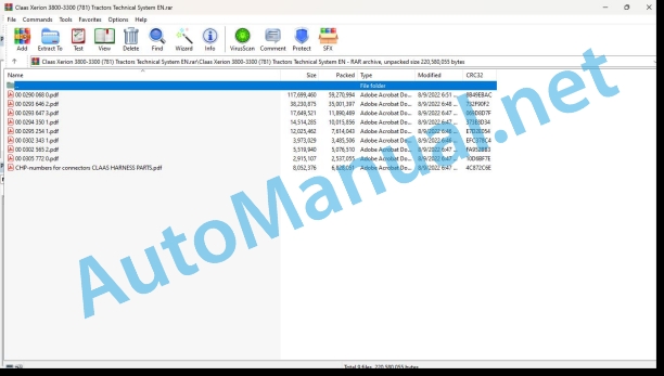
00 0290 068 0.pdf
00 0293 646 2.pdf
00 0293 647 3.pdf
00 0294 350 1.pdf
00 0295 254 1.pdf
00 0302 343 1.pdf
00 0302 565 2.pdf
00 0305 772 0.pdf
CHP-numbers for connectors CLAAS HARNESS PARTS.pdf
00 0290 068 0.pdf:
XERION 3800 TRAC / TRAC VCXERION 3300 TRAC / TRAC VCfrom machine 781 00110
Table of contents
CCN explanation
CCN (CLAAS Component Number)
Electric systems standard
Overview
Hydraulic system standard
Overview
CCN (CLAAS Component Number)
Introduction
Safety rules
Safety and hazard precautions
Validity of manual
Overview
01 Engine
0135 Cooling system
Engine cooling (reversing fan)
Measured value tables
Description of function
Thermocouple with elastomer insert
0150 Engine attachment parts
Main power supply, starter
Description of function
Diagnosis table
Pin assignment
Interconnection list
Starting the diesel engine, diesel engine speed adjustment
For diesel engine according to exhaust gas standard TIER 3 (ACERT)
Description of function
Electronic throttle switching logic
Diagnosis table
Pin assignment
Interconnection list
0155 Engine control
Diesel engine monitoring
Description of function
Measured values table
Diagnosis table
Pin assignment
Interconnection list
02 Gearbox / Clutch / Universal drive shaft
0238 Gearbox control
Transmission control
Description of function
Measured values table
Diagnosis table
Pin assignment
Interconnection list
Limp Home
Description of function
Diagnosis table
Pin assignment
Interconnection list
0242 Differential
Locking differentials
Description of function
Measured values table
Diagnosis table
Pin assignment
Interconnection list
03 Chassis
0310 Axle
Lock floating axle
Description of function
Measured values table
Measured value table for hydraulics
Diagnosis table
Pin assignment
Interconnection list
0335 Ground drive
Drive management
Description of function
Measured values table
Diagnosis table
Pin assignment
Interconnection list
04 Brake
0405 Service brake
Service brake (up to 78100959)
Description of function
Adjusting brake actuation after repair work
Measured values table
Measured value table for braking hydraulics
Diagnosis table
Braking system hydraulic components (Bosch Rexroth)
Pin assignment
Interconnection list
Service brake (from 78100960)
Measured values table
Description of function
Charging the brake accumulator
Designation
Description of function
Testing and measurements
Checking the max. brake pressure
Braking system hydraulic components (Safim)
0415 Parking brake
Parking brake
Description of function
0420 Trailer air brake
Compressed-air trailer brake system
Line system circuit diagram 1
Key to diagram
Component connection designations
2 line system circuit diagram
Key to diagram
Component connection designations
Position of the components. Compressed-air trailer brake system
0425 Trailer hydraulic brake
Trailer brake, central lubrication
Description of function
Measured values table
Diagnosis table
Pin assignment
Interconnection list
05 Steering
0505 Steering
Steering system basic principles
System concept
Floating axle steered by Orbitrol steering unit
Cab in centre position: Standard steering 1, control lever steering, small crab steering, 4-wheel steering
Key to diagram
Description of function
Orbitrol-steered rigid axle
Standard steering 2, control lever steering, small crab steering, 4-wheel steering
Key to diagram
Description of function
Electronic steering mode (steer by wire)
Fully electronic steering, diagonal crab steering, crab steering, synchronous steering
Key to diagram
Description of function
Emergency steering
Emergency steering
Key to diagram
Description of function
Measured value table for steering hydraulics
0510 Automatic steering
AUTO PILOT
Description of function
Measured values table
Logic table: Emergency steering pump monitoring
Logic table: Cab position detection
Diagnosis table 28
Pin assignment
Interconnection list
06 Lift device
0605 Rear power lift
Three-point braces
Description of function
Diagnosis table
Pin assignment
Interconnection list
Rear hydraulic system
A52 module multifunction handle
Description of function
Measured values table
Rear power lift position sensor basic adjustment (B139-2)
Diagnosis table
Pin assignment
Interconnection list
Swivel power lift
Description of function
Description of function
Measured values table
0610 Front power lift
Front hydraulic system
A52 module multifunction handle
Description of function
Measured values table
Sensor basic adjustment (B139-1)
Diagnosis table
Pin assignment
Interconnection list
08 Drives
0802 Rear PTO
Rear PTO shaft circuit
Description of function
Measured values table
Logic table: Rear PTO switch S114 (inside cab)
Logic table: Rear PTO switch U30 (external mud guard)
Diagnosis table 7
Pin assignment
Interconnection list
Rear PTO shaft circuit (automatic)
Measured values table
Description of function
Diagnosis table 15
Pin assignment
Interconnection list
0809 Hydraulic drive
Additional PTO – Power hydraulics
Description of function
Measured values table
Logic table: Secondary PTO shaft (PTO2) switch S113
Diagnosis table
Pin assignment
Interconnection list
09 Hydraulic system
0900 Hydraulic system – General
Road travel circuit, constant pressure circuit
Description of function
Measured values table
Diagnosis table
Pin assignment
Interconnection list
Hydraulic system – Testing and measuring
Measured value table for pumps
Measured value table for working hydraulics
Measured value table for steering hydraulics
Measured value table for braking hydraulics
Measured value table for power hydraulics – auxiliary hydraulics
0910 Pumps
PFC Pump (Pressure Flow Controlled)
Compensating valve
Key to diagram
Description of function
Comment on PFC pump illustration
Starting position (engine OFF)
Key to diagram
Description of function
Stand-by
Key to diagram
Description of function
Pump starts pumping
Key to diagram
Description of function
Constant volume flow
Key to diagram
Description of function
Regulating
Key to diagram
Description of function
Maximum pressure limit (pressure relief valve function)
Key to diagram
Description of function
0920 Valves
Steering valve block
Steering valve block
Key to diagram
Main valve block
Key to diagram
EHM 18 control unit
Key to diagram
Function – Neutral
Description of function
Function – Float position
Description of function
Function – Actuation of a consumer (pressure build-up in B)
Description of function
Three-point braces valve block
Key to diagram
Swing power lift valve block
Key to diagram
Cab valve block (from 78100110)
Key to diagram
Cab valve block (from 78100428)
Key to diagram
Cab valve block (from 78101359)
Key to diagram
Brake valve (up to 78100959)
Key to diagram
Brake valve (from 78100960)
Key to diagram
Front, rear quick-release coupling (from 78100110)
Key to diagram
Additional control units
Description of function
Measured values table
Measured value table for hydraulics
Diagnosis table
Pin assignment
Interconnection list
Blue auxiliary control valve
Description of function
Measured values table
Diagnosis table
Pin assignment
Interconnection list
0930 Cylinders
Swing power lift hydraulic cylinder
Key to diagram
0935 Hydraulic system control / monitoring
Machine monitoring (hydraulics)
Description of function
Measured values table
Diagnosis table
Pin assignment
Interconnection list
0940 Power hydraulics
Power hydraulics – auxiliary hydraulics
Description of function
Technical specifications for the auxiliary hydraulic pump (227)
Purge valve – charge pump delivery volume at different engine speeds
Measured value table for power hydraulics – auxiliary hydraulics
Multifunction valve A (7001) and B (7002)
Description of function
0980 Hydraulic circuit diagram
Overall hydraulics circuit diagram (up to 78100959)
Key to diagram
Overall hydraulics circuit diagram (from 78100960)
Key to diagram
Working hydraulics
Working hydraulics circuit diagram from machine 78100110
Key to diagram
Steering hydraulics
Steering valve VI
Key to diagram
Braking hydraulics circuit diagram up to machine no. 78100959
Key to diagram
Braking hydraulics circuit diagram (from 78100960)
ECCOM 3.5 transmission hydraulics circuit diagram
Key to diagram
Power hydraulics – auxiliary hydraulics
Power hydraulics – auxiliary hydraulics circuit diagram
Key to diagram
Description of function
Multifunction valve A (7001) and B (7002)
Description of function
Cab hydraulics (from 78100110)
Key to diagram
Cab hydraulics (from 78100428)
Key to diagram
Cab hydraulics (from 78101359)
Key to diagram
10 Electrical / Electronic equipment
1005 Power supply
ISO signal socket
Description of function
Diagnosis table
Pin assignment
Interconnection list
Attachments connection
Description of function
Pin assignment
Interconnection list
Auxiliary sockets
Pin assignment
Interconnection list
1010 Central electrics
Central electrics from machine no. 78100322
Electronic components
1012 Modules / sensors
Module illustration
Overview 1
Overview 2
Overview 3
Module A6 – Automatic air conditioner (ACM)
Module A7 – Cab fan (CFC)
Module A9 – AUTO PILOT (ATP)
Key to diagram
Module A15 – Engine control module (ECM) – CATERPILLAR (CAT C9)
Module A30 – CEBIS terminal
Module A33 – Sidefinder – Pathfinder
Module A55 – Electro-hydraulic steering connector 1 (EHL)
Module A055 – Electro-hydraulic steering connector 2 (EHL)
Module A56 – VDC (vehicle drive control)
Module A57 – Gearshift control (TCU)
Module A58 – Electronic power lift control (EHR)
Module A59-1 Valve control (VCU)
Module A59-2 Valve control (VCU)
Module A60 – Hydraulic control unit (HYD)
Module A61 – Fieldwork computer XERION (XIF)
Module A61 – Fieldwork computer XERION (XIF) – rear PTO shaft circuit (automatic)
Module A62 – External control (EXT)
Module A66 – GPS PILOT (GPM)
Module A70 – Power Hydraulics (PHM)
1020 Driving lights
Warning beacons
Pin assignment
Interconnection list
European turn-signal indicator system
Description of function
Diagnosis table
Pin assignment
Interconnection list
Turn-signal indicator system (USA)
Description of function
Diagnosis table
Pin assignment
Interconnection list
Rearlight, side light
Pin assignment
Interconnection list
Dipped beam, main beam
Pin assignment
Interconnection list
Brake light, reversing light
Diagnosis table
Pin assignment
Interconnection list
1025 Working lights
Working lights I
Diagnosis table
Pin assignment
Interconnection list
Worklights
Description of function
Pin assignment
Interconnection list
1030 Board computer / Indicators
ISO terminal, ISO operation
Description of function
Diagnosis table
Interconnection list
1035 Operation / Multifunction control lever
External operation (EXT module)
Description of function
Diagnosis table
Pin assignment
Programmable functions (F keys)
A52 module multifunction handle
Description of function
Diagnosis table
Pin assignment
Interconnection list
1080 Electronic circuit diagram
01a Main power supply, diesel engine starter
Key to diagram
02a Starting the diesel engine, diesel engine speed adjustment
Key to diagram
03a Diesel engine cut-off system
Key to diagram
04a Road travel circuit, constant pressure circuit
Key to diagram
Key to diagram
05a Terminal
Key to diagram
06a CAN-Bus, power supply modules
Key to diagram
07a Rear PTO shaft circuit
Key to diagram
08a Secondary PTO shaft – power hydraulics
Key to diagram
09a External operation (EXT module)
Key to diagram
10a ISO terminal, ISO operation
Key to diagram
Key to diagram
11a ISO signal socket
Key to diagram
12a Programmable functions (F keys)
Key to diagram
13a Attachments connection
Key to diagram
14a Three-point braces
Key to diagram
15a Rear PTO shaft engaging (automatic)
Key to diagram
20a Front hydraulics
Key to diagram
21a Rear hydraulics EHR
Key to diagram
22a Service valves, additional control units
Key to diagram
23a Blue service valve
Key to diagram
26a Machine monitoring (hydraulics)
Key to diagram
Key to diagram
28a EHL (AUTO PILOT), cab position detection
Key to diagram
30a Warning beacon
Key to diagram
31a Locking the floating axle
Key to diagram
32a Locking differentials
Key to diagram
33a Cab rotation
Key to diagram
36a Indicator system – Europe
Key to diagram
36b Turn indicator system (USA)
Key to diagram
37a Windscreen wiper, windscreen washer
Key to diagram
38a Automatic air conditioner
Key to diagram
39a Operator’s seat
Key to diagram
40a Auxiliary sockets
Key to diagram
41a Driving management, brake, parking brake
Key to diagram
42a Limp Home
Key to diagram
43a Trailer brake, central lubrication system
Key to diagram
44a Transmission control
Key to diagram
45a Lighting main circuit, taillight, position light
Key to diagram
46a Dipped beam, main beam, dipped beam changeover
Key to diagram
47a Worklights I
Key to diagram
48a Worklights II
Key to diagram
49a Horn, brake light, reversing light
Key to diagram
50a Instrument lighting, broadcast radio, mirror adjustment
Key to diagram
1085 Networks
CAN-Bus system with GPS PILOT II
Description of function
Description of function
Measured value table for 250 kB vehicle CAN-Bus
Measured value table for 250 kB hydraulics system CAN-Bus
Measured value table for J1939 CAN-Bus
Measured value table for ISO 11783 CAN-Bus
Pin assignment
Interconnection list
1090 Accessories
Connector database (chp CLAAS)
12 Cab / Operator’s platform
1210 Cab
Cab rotation
Description of function
Measured values table
Cab locked sensor (B147)
Diagnosis table
Measured value table for hydraulics
Pin assignment
Interconnection list
Windscreen wiper, windscreen washer
Pin assignment
Interconnection list
1225 Mirror
Mirror adjustment, instrument lighting
Pin assignment
Interconnection list
1230 Seat
Driver’s seat
Description of function
Pin assignment
Interconnection list
1240 Air condition
Automatic air conditioner
Description of function
Measured values table
Test menu:
Test menu operation
Pin assignment
Interconnection list
92 Diagnosis
9210 Error codes machine
FMI (Failure Mode Indicator)
FMI 00 (Signal too high)
FMI 01 (Signal too low)
FMI 02 (Erratic signal)
FMI 03 (Voltage too high)
FMI 04 (Voltage too low)
FMI 05 (Current too low)
FMI 06 (Current too high)
FMI 07 (Mechanical failure)
FMI 08 (Abnormal frequency signal)
FMI 09 (Communication error)
FMI 10 (Rate of signal change too fast)
FMI 11 (multiple faults)
FMI 12 (ECU defective)
FMI 13 (Signal outside of calibration range)
FMI 16 (Parameter not available)
FMI 17 (ECU not responding)
FMI 18 (Power supply failure)
FMI 19 (Software conditions not met)
FMI 95 (no signal change)
FMI 96 (CAN Bus system defective)
FMI 97 (Erratic condition)
FMI 98 (Warning)
FMI 99 (Info)
XERION fault codes (type 781)
DTC (Diagnostic Trouble Code) overview
9220 Error codes engine (J1939)
Diesel engine fault codes – J 1939 / Engine diagnosis / Component position
Description of function
CATERPILLAR C9 (TIER3)
Fault code MB, CAT TIER 3 and 4
Position of components
Electric system
A Terminal / modules
B Sensors
E Lighting
G Voltage sources
H Signal system / signal light
M Motor (electric)
R Potentiometer / resistor
S Switch / pushbutton – Cab operation
U Switch – external operation
Y Solenoid coils
Z Actual value switch
Hydraulic system
1000 Oil reservoir / oil filter / oil cooler
2000 Pump / motor
3000 Hydraulic cylinders
4000 Restrictor / orifice plate
5000 Accumulator
6000 Valves – mechanically actuated
7000 Valves – hydraulically actuated
8000 Couplings / connections
9000 Measuring points / gauges
Component grid – Electrics – Component position
00 0293 646 2.pdf:
Contents
1 Overall hydraulic system
Hydraulic circuit diagram up to no. 78100109
Overall circuit diagram
Designations
Hydraulic circuit diagram from no. 78100110
Overall circuit diagram
Designations
PFC pump – compensation valve
Designations
Description of
PFC pump – initial position (Engine OFF)
Designations
Description of
PFC pump – low-pressure standby
Designations
Description of
PFC pump – pump changes to delivery mode
Designations
Description of
PFC pump – constant volume flow
Designations
Description of
PFC pump – downstroking
Designations
Description of
PFC pump – maximum pressure limitation (pressure relief valve function)
Designations
Description of
2 Steering hydraulics
System concept
Description
Emergency steering mode
Hydraulic circuit diagram
Key to diagram
Function
Standard steering 1: (Floating axle is steered by Orbitrol steering unit)
Hydraulic circuit diagram
Key to diagram
Function
Standard steering 2: (Rigid axle is steered by Orbitrol steering unit)
Hydraulic circuit diagram
Key to diagram
Function
Fully electronic steering mode (steer-by-wire)
Hydraulic circuit diagram
Key to diagram
Function
Steering valve VI
Graphics
Key to diagram
3 Working hydraulics
Hydraulic circuit diagram up to no. 78100109
Working hydraulics circuit diagram
Key to diagram
Hydraulic circuit diagram from no. 78100110
Working hydraulics circuit diagram
Key to diagram
Main valve block
Graphics
Key to diagram
EHM18 control unit
Graphics
Key to diagram
Neutral function
Float position function
Function: Actuation of a consumer (pressure build-up in B)
Three-point hitch braces
Graphics
Key to diagram
Swing power lift – hydraulic valve
Graphics
Key to diagram
Key to diagram
Cab valve block (II) – up to serial no. 109
Graphics
Key to diagram
Description of function
Cab valve block (II) – from serial no. 110
Graphics
Designations
Swing power lift -hydraulic cylinder
Graphics
Rotate cab, raise/lower cab – from serial no. 110
Graphics
Designations
Front, tail quick-release couplings – up to serial no. 109
Graphics
Key to diagram
Front, tail quick-release couplings – from serial no. 110
Graphics
Key to diagram
4 Brake hydraulics
Hydraulic circuit diagram
Brake hydraulics circuit diagram
Key to diagram
Description
Adjusting the brake actuation following repair work
Main brake valve VII
Key to diagram
Location of components – Accumulator
5 Compressed-air system
1- and 2-line system, 2-line system
Circuit diagram of 1- and 2-line system
Key to diagram
Designations of component connections
Circuit diagram of 2-line system
Key to diagram
Designations of component connections
Location of components
6 Auxiliary hydraulic system
Hydraulic circuit diagram
Auxiliary hydraulic system circuit diagram
Key to diagram
Components
Description
Multifunction valve A (7001)Multifunction valve B (7002)
7 Testing and measuring
Measured value tables
Measured value table for pumps
Working hydraulics measured value table
Steering hydraulics measured value table
Brake hydraulics measured value table
Auxiliary hydraulic system measured value table
8 Location of components
Overview
Main sub-assemblies (I to XI)
Single components of main valve block (I)
Single components of cab valve block (II) up to serial no. 78100109
Single components of cab valve block (II) from serial no. 78100110
Single components of distribution block (III)
Single components of Orbitrol steering valve (IV)
Single components of steering sense valve (V)
Single components of EHL (electro-hydraulic steering) valve block (VI)
Single components of main brake valve (VII)
Single components of working hydraulics variable-displacement pump (VIII)
Single components of steering hydraulics variable-displacement pump (IX)
Single components of three-point hitch braces (X)
Single components of power lift swing (XI)
Further single components
00 0293 647 3.pdf:
Contents
1 Introduction
Structure of electrical documentation
Circuit diagram
Grid co-ordinates
Interconnection list
CLAAS standard:
2 Electrics – basic principles
Measuring resistance
Key to diagram
Description of function
Measuring voltage
Key to diagram
Description of function
Measuring current
Key to diagram
Description of function
3 Hydraulics – basic principles
Hydraulic pressure in motionless liquids
Diagram 1
Key to diagram
General principles:
Hydraulic pressure in moving liquids
Diagram 1
Key to diagram
Diagram 2
Key to diagram
General principles:
Hydraulic flow quantity
Key to diagram
General principles:
Measuring pressure
Key to diagram
General principles:
Measuring flow quantity
Key to diagram
Description of function
Graphic symbols in fluidics
Graphic symbols and explanations
4 Central terminal compartment
Central terminal compartment 0596 781.2 (up to serial no. 50)
Top view
Rear view
Electronic components
Fuses (serial numbers 78100005 – 78100020)
Fuses (serial numbers 78100021 – 78100050)
Central terminal compartment 0596 783.0 (from serial no. 50)
Top view
Rear view
Electronic components
Fuses (serial numbers 78100051 – 78100109)
5 Modules
Module representation
Overview 1
Overview 2
Overview 3
Module pin assignment
Module A006 – automatic climate control
Module A007 – cab fan governor
Module A015 – electronic engine control CAT
Module A030 – Terminal Cebis
Module A055 Electro-hydraulic steering (EHL) connector 1, up to vehicle no. 50
Module A055 Electro-hydraulic steering (EHL) connector 2, up to vehicle no. 50
Module A055 Electro-hydraulic steering (EHL) connector 1, from vehicle no. 51
Module A055 Electro-hydraulic steering (EHL) connector 2, from vehicle no. 51
Module A056 – VDC (vehicle drive control)
Module A057 – gearshift control (TCU)
Module A058 – Lift control (EHR)
Module A059-1 valve control (VCU)
Module A059-2 – valve control (VCU)
Module A060 – hydraulic control unit (HYD)
Module A061 – fieldwork computer XERION (XIF)
Module A062 – external control (EXT)
Module A070 – power hydraulics (PHM)
6 Circuit diagrams
01a Main power supply, diesel engine electric starting motor
Circuit diagram up to serial no. 50 (DIN A 3)
Key to diagram
Description of function
Diagnosis table 1
Connector pin assignment
Interconnection list
01b Main power supply, diesel engine electric starting motor
Circuit diagram from serial no. 51 (DIN A 3)
Key to diagram
Description of function
Diagnosis table 1
Connector pin assignment
Interconnection list
02a Starting the diesel engine, diesel engine speed adjustment
Circuit diagram up to serial no. 50 (DIN A 3)
Key to diagram
Description of function
Electronic throttle switching logics
Diagnosis table 2
Connector pin assignment
Interconnection list
02b Starting the diesel engine, diesel engine speed adjustment
Circuit diagram from serial no. 51 (DIN A 3)
Key to diagram
Description of function
Electronic throttle switching logics
Diagnosis table 2
Connector pin assignment
Interconnection list
03a Diesel engine cut-off system
Circuit diagram (DIN A3)
Key to diagram
Measuring value table
Description of function
Diagnosis table 3
Connector pin assignment
Interconnection list
04a Road travel circuit, constant pressure circuit
Circuit diagram (DIN A3)
Key to diagram
Measuring value table
Description of function
Diagnosis table 4
Connector pin assignment
Interconnection list
05a Terminal
Circuit diagram (DIN A3)
Key to diagram
Description of function
Connector pin assignment
Interconnection list
06a CAN bus
Circuit diagram up to serial no. 50 (DIN A 3)
Key to diagram
Description of function
CAN BUS network
Measured value table 250 kB vehicle CAN bus (Vehicle CAN bus)
Measured value table 250 kB CAN bus hydraulic system
Measured value table J1939 CAN bus
Measured value table ISO 11783 CAN bus
Connector pin assignment
Interconnection list
06b CAN bus
Circuit diagram from serial no. 51 (DIN A 3)
Key to diagram
Description of function
CAN bus network
Measured value table 250 kB vehicle CAN bus (Vehicle CAN bus)
Measured value table 250 kB CAN bus hydraulic system
Measured value table J1939 CAN bus
Measured value table ISO 11783 CAN bus
Connector pin assignment
Interconnection list
07a Rear PTO shaft circuit
Circuit diagram up to serial no. 50 (DIN A 3)
Key to diagram
Measuring value table
Description of function
Logics table: Rear PTO switch S114 (internal, in cab)
Logics table: Rear PTO switch U30 (external, on mud guard)
Diagnosis table 7
Connector pin assignment
Interconnection list
07b Tail PTO shaft circuit
Circuit diagram from serial no. 51 (DIN A 3)
Key to diagram
Measuring value table
Description of function
Logics table: Rear PTO switch S114 (internal, in cab)
Logics table: Rear PTO switch U30 (external, on mud guard)
Diagnosis table 7
Connector pin assignment
Interconnection list
08a PTO shaft circuit II Auxiliary power take-off
Circuit diagram up to serial no. 50 (DIN A 3)
Key to diagram
Measuring value table
Description of function
Logic table: PTO 2 auxiliary power take-off switch S113
Diagnosis table 8a
Connector pin assignment
Interconnection list
08b PTO shaft circuit II Auxiliary power take-off / Power hydraulics
Circuit diagram from serial no. 51 (DIN A 3)
Key to diagram
Measuring value table
Description of function
Logic table: Auxiliary power take-off PTO2 switch S113
Diagnosis table 8
Connector pin assignment
Interconnection list
09a External operation (EXT module)
Circuit diagram (DIN A3)
Key to diagram
Description of function
Diagnosis table 9
Connector pin assignment
Interconnection list
10a ISO terminal, ISO operation
Circuit diagram (DIN A3)
Key to diagram
Description of function
Diagnosis table 10
Interconnection list
11a ISO signal socket
Circuit diagram (DIN A3)
Key to diagram
Description of function
Diagnosis table 11
Connector pin assignment
Interconnection list
12a Programmable functions (F keys)
Circuit diagram up to serial no. 50 (DIN A 3)
Key to diagram
A52 Multifunction handle module
Description of function
Diagnosis table 12
Connector pin assignment
Interconnection list
12b Programmable functions (F keys)
Circuit diagram from serial no. 51 (DIN A 3)
Key to diagram
A52 Multifunction handle module
Description of function
Diagnosis table 12
Connector pin assignment
Interconnection list
13a Connection of semi-mounted implements
Circuit diagram (DIN A3)
Key to diagram
Description of function
Connector pin assignment
Interconnection list
14a Three-point braces
Circuit diagram (DIN A3)
Key to diagram
Description of function
Diagnosis table 14
Connector pin assignment
Interconnection list
15a Tail PTO shaft engaging (automatic)
Circuit diagram (DIN A3)
Key to diagram
Measuring value table
Description of function
Diagnosis table 15
Connector pin assignment
Interconnection list
20a Front hydraulics
Circuit diagram (DIN A3)
Key to diagram
A52 Multifunction handle module
Measuring value table
Description of function
Diagnosis table 20
Connector pin assignment
Interconnection list
21a Tail hydraulics EHR
Circuit diagram (DIN A3)
Key to diagram
A52 Multifunction handle module
Measuring value table
Description of function
Diagnosis table 21
Connector pin assignment
Interconnection list
22a Service valves, additional control units
Circuit diagram (DIN A3)
Key to diagram
Measuring value table
Description of function
Diagnosis table 22
Connector pin assignment
Interconnection list
23a Blue service valve
Circuit diagram (DIN A3)
John Deere Repair Technical Manual PDF
John Deere Repair Technical Manual PDF
John Deere 16, 18, 20 and 24HP Onan Engines Component Technical Manual CTM2 (19APR90)
John Deere Repair Technical Manual PDF
John Deere Repair Technical Manual PDF
John Deere Repair Technical Manual PDF
John Deere Parts Catalog PDF
John Deere Tractors 7500 Parts Catalog CPCQ26568 30 Jan 02 Portuguese
John Deere Repair Technical Manual PDF
John Deere Repair Technical Manual PDF
John Deere Diesel Engines POWERTECH 2.9 L Component Technical Manual CTM126 Spanish
John Deere Repair Technical Manual PDF
John Deere DF Series 150 and 250 Transmissions (ANALOG) Component Technical Manual CTM147 05JUN98
John Deere Repair Technical Manual PDF

