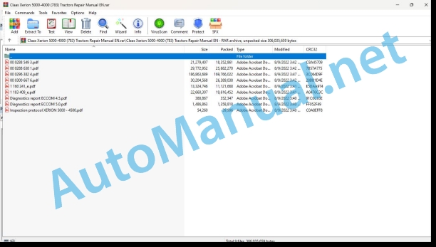
Claas Xerion 5000-4000 (783) Tractors Repair Manual EN
$300.00
- Model: Xerion 5000-4000 (783) Tractors
- Type Of Manual: Repair Manual
- Language: EN
- Format: PDF(s)
- Size: 260 MB
File List:
00 0288 549 3.pdf
00 0288 638 1.pdf
00 0296 382 4.pdf
00 0300 667 6.pdf
1 160 241_e.pdf
1 183 409_e.pdf
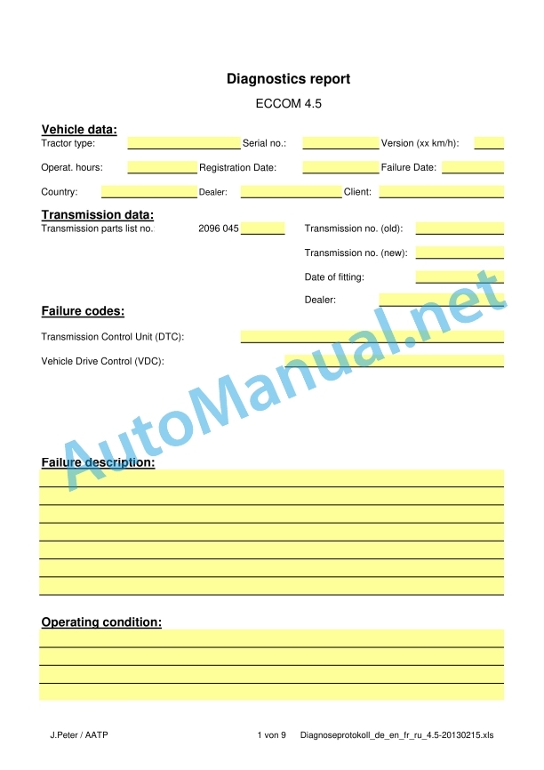
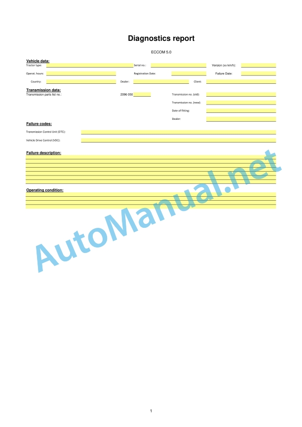
Diagnostics report ECCOM 4.5.pdf
Diagnostics report ECCOM 5.0.pdf
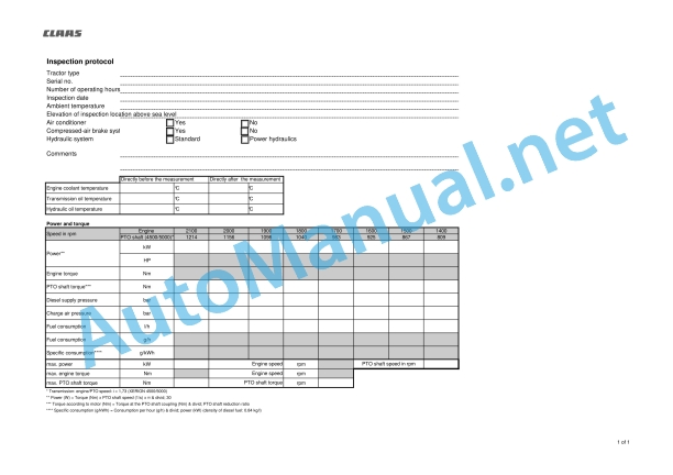
Inspection protocol XERION 5000 – 4500.pdf
00 0288 549 3.pdf:
ZF ECCOM 5.0
Table of contents
Introduction
General information
Validity of manual
Using the manual
Text and figures
Document structure based on sub-assemblies
Search and find
Directions
Abbreviations
Technical terms
General repair instructions
Technical specifications
Information on technically correct repairs
Self-locking bolts
Liquid locking compound
Steel roller chains
Tensioning
Chain connector
Chain connector type E with spring
Chain connector type G with wire
Chain connector type S with cotter pins
Taper ring fasteners
Dismounting
Installation
Gib head key connections
Dismounting
Installation
Lock collar bearing
Dismounting
Installing
Adapter sleeve bearing
Dismounting
Installation
Chuck bushing
Removing
Dismounting of version A
Dismounting of version B
Installing
Chuck bushing version A
Chuck bushing version B
Circlips
Ferrule fittings
Screwing in
Leaky ferrule fittings
Sealing cone fittings
Hydraulic hoses
Hose placement
Radial shaft seals
Treatment of sealing faces
Drive belts / drive chains
Diesel engine
Alternator
Spare parts
Reason of damage
Tightening torques
Tightening torques for metric ISO screw thread
Tightening torques for metric fine thread
Tightening torques for hydraulic fittings with ferrule
Tightening torques for screwed pipe connections with sealing cone joint and hydraulic threaded joints with soft core seal
Tightening torques for hydraulic male connectors SDS shape B and E
Tightening torques for hydraulic male connectors SDE shape H, with adjustable direction
Tightening torques for hydraulic swivel screw fittings
Tightening torque for hollow screws (with copper sealing ring)
Tightening torques for brake line screw fittings
Tightening torque for tubes with O-ring and union nuts
Tightening torques for worm drive hose clamps
Tightening torques for hose clamps with round pins
Technical specifications
Operating materials
CCN explanation
CCN (CLAAS Component Number)
Electric system standard
Overview
Hydraulic system standard
Overview
CCN (CLAAS Component Number)
General information
Important
Hazard signs
Signal word
General safety and accident prevention regulations
Combine-harvester safety and accident prevention regulations
First aid measures
Leaving the machine
Adjusting and maintenance work
Danger of injury from hydraulic liquid
Hydraulic accumulators
Battery isolating switch
Jacking up the machine
Putting the machine out of operation
Welding work
02 Gearbox / Clutch / Universal drive shaft
0202 Complete component
Diagnostic protocol
Removing / installing the gearbox
Separating / joining the gearbox housing
Technical specifications
Work preparation
Special tool
Special tool
Separating
0220 Mechanical reverser
Clutch KR
Technical specifications
Work preparation
Special tool
Removing
Disassembling
Assembling
Installing
Clutch KV
Technical specifications
Work preparation
Special tool
Removing
Disassembling
Assembling
Installing
0230 Mechanical gearbox
Engine input shaft
Technical specifications
Work preparation
Special tool
Removing
Disassembling
Installing
Central shaft
Technical specifications
Work preparation
Special tool
Removing
Disassembling
Assembling
Installing
Brake BG
Technical specifications
Work preparation
Special tool
Removing
Disassembling
Assembling
Installing
Shifter roller
Technical specifications
Work preparation
Special tool
Removing
Disassembling
Assembling
Installing
Clutches K3/K4 and planetary gear P4
Technical specifications
Work preparation
Special tool
Removing
Disassembling
Assembling
Installing
Planetary gears P1/P2/P3
Technical specifications
Work preparation
Special tool
Removing planetary gear P1
Disassembling planetary gear P1
Removing planetary gear P2
Disassembling planetary gear P2
Removing planetary gear P3
Disassembling planetary gear P3
Assembling planetary gear P3
Assembling planetary gear P2
Assembling planetary gear P1
Assembling the profile tube
Installing P3
Installing P2
Installing P1
Clutch K1/K2
Technical specifications
Work preparation
Special tool
Removing
Disassembling
Assembling
Front axle output shaft
Technical specifications
Work preparation
Special tool
Removing
Disassembling
Assembling
Installing
Rear axle output shaft
Technical specifications
Work preparation
Special tool
Removing
Installing
PTO shaft
Technical specifications
Work preparation
Special tool
Removing the output flange
Removing the PTO shaft
Disassembling the PTO shaft
Assembling the PTO shaft
Installing the PTO shaft
Installing the output flange
PTO shaft clutch
Technical specifications
Work preparation
Special tool
Removing the PTO shaft housing
Removing the PTO shaft clutch
Disassembling the PTO clutch
Assembling the PTO shaft clutch
Disassembling the housing
Assembling the housing
Installing the PTO shaft clutch
Adjusting the PTO shaft axial play
Calculating the axial play:
Spur gear Z6
Technical specifications
Work preparation
Special tool
Removing
Installing
Spur gear Z23
Technical specifications
Special tool
Removing
Installing
Assembling
Spur gear Z2, Z3 and pump drive
Technical specifications
Work preparation
Special tool
Removing
Oil tubes
Spur gear Z2, Z3 and pump drive
Installing
Spur gear Z3
Spur gear Z2 and pump drive
Oil tubes
Spur gear Z33
Technical specifications
Work preparation
Special tool
Removing
Installing
Intermediate gear wheel Z24
Technical specifications
Work preparation
Special tool
Removing
Installing
0232 Hydraulical gearbox
Hydrostatic drive
Technical specifications
Work preparation
Special tool
Removing
Installing
0238 Gearbox control
System pressure control block
Technical specifications
Work preparation
Special tool
Removing
Disassembling
Assembling
Installing
Clutch control block
Technical specifications
Work preparation
Special tool
Removing
Disassembling
Assembling
Installing
Sensors / valves / filters
Technical specifications
Work preparation
Removing
Installing
0255 Gearbox cooling system
Gearbox pump (ECCOM 5.0)
Technical specifications
Work preparation
Removing
Installing
00 0288 638 1.pdf:
ZF ECCOM 3.5 / 4.5
Table of contents
Introduction
General information
Validity of manual
Handling of this manual
Texts and figures
Document structure based on subassemblies
Search and find
Directions
Abbreviations
Technical terms
Converting metric units to US units
Pressure
Ground speed
Acceleration (vibration intensity)
Viscosity
Temperature
Electric system
General repair instructions
Technical specifications
Information on technically correct repairs
Self-locking bolts
Liquid locking compound
Steel roller chains
Tensioning
Chain connector
Taper ring fasteners
Dismounting
Installing
Gib head key joints
Dismounting
Installation
Lock collar bearing
Dismounting
Installing
Adapter sleeve bearings
Dismounting
Installation
Chuck bushing
Removing version A
Removing version B
Installation
Version A chuck bushing
Version B chuck bushing
Circlips
Ferrule joints
Screwing in
Leaky ferrule joints
Sealing cone joints
Hydraulic hoses
Hose placement
Spare parts
Torque settings
Tightening torques for metric standard threads
Tightening torque for metric fine threads
Tightening torques for hydraulic screw fittings with ferrule according to DIN 3861
Tightening torques for hydraulic screw fittings and air conditioner screw fittings with sealing cone and O-ring according to DIN 3865
Tightening torques for SDS hydraulic male connectors
Tightening torques for direction-adjustable SDE hydraulic male connectors
Tightening torques for hydraulic swivel fittings
Tightening torques for hollow screws DIN 7643
Tightening torques for brake line screw fittings
Tightening torques for worm-type threaded clips
Tightening torques for hose clamps with round pins
Tightening torques for tyres
General information
Important
Identification of warning and danger signs
General safety and accident prevention regulations
First aid measures
Danger of injury from hydraulic liquid
Leaving the machine
Putting the machine out of operation
Jacking up the machine
Adjustment and maintenance work
Welding work
02 Gearbox / Clutch / Universal drive shaft
0202 Complete component
Diagnostic protocol
Removing / installing the gearbox
Transmission housing
Technical specifications
Work preparation
Special tool
Separating the halves of the housing
Joining the halves of the housing
0220 Mechanical reverser
Clutch KR
Technical specifications
Work preparation
Special tool
Removing
Disassembling
Assembling
Installing
Clutch KV
Technical specifications
Work preparation
Special tool
Removing
Disassembling
Assembling
Installing
Adjusting the axial play
Special tool
Adjusting the axial play of the clutches and spur gears
0230 Mechanical gearbox
Engine input shaft
Technical specifications
Work preparation
Special tool
Removing
Disassembling
Installing
Central shaft
Technical specifications
Work preparation
Special tool
Removing
Disassembling
Assembling
Installing
Multi-disc brake BG
Technical specifications
Work preparation
Special tool
Removing
Disassembling
Assembling
Installing
Shifter roller
Technical specifications
Work preparation
Special tool
Removing
Disassembling
Assembling
Installing
Clutches K3/K4 and planetary gear P4
Technical specifications
Work preparation
Special tool
Removing
Disassembling
Assembling
Installing
Planetary gears P1/P2/P3
Technical specifications
Work preparation
Special tool
Removing
Removing P1
Disassembling planetary gear P1
Removing planetary gear P2
Disassembling planetary gear P2
Removing planetary gear P3
Disassembling planetary gear P3
Assembling planetary gear P3
Assembling planetary gear P2
Assembling planetary gear P1
Assembling the profile tube
Clutch K1/K2
Technical specifications
Special tool
Removing
Disassembling
Assembling
Front axle output shaft (ECCOM 3.5 / 4.5)
Technical specifications
Work preparation
Special tool
Removing
Installing
Rear axle output shaft
Technical specifications
Work preparation
Special tool
Removing the output flange
Removing the output shaft
Disassembling the output shaft
Assembling the output shaft
Installing the output shaft
Installing the output flange
PTO (ECCOM 3.5 / 4.5)
Technical specifications
Work preparation
Special tool
Disconnecting the PTO from the intermediate housing
Disassembling
Disassembling the PTO clutch
Assembling
Installing
Spur gear Z4
Technical specifications
Removing the spur gear (Z4)
Installing the spur gear (Z4)
Spur gear Z5
Special tool
Removing
Removing the spur gear (Z5)
Installing the spur gear (Z5)
Spur gear Z6
Technical specifications
Work preparation
Special tool
Removing
Removing gear (Z6)
Installing gear (Z6)
Spur gear Z23
Technical specifications
Special tool
Removing
Installing
Spur gears Z2 / Z3
Technical specifications
Work preparation
Special tool
Removing
Removing gear (Z2)
Disassembling the gear (Z2)
Assembling the gear (Z2)
Installing gear (Z2)
Removing gear (Z3)
Disassembling the gear (Z3)
Installing gear (Z3)
Spur gear Z33
Technical specifications
Work preparation
Special tool
Removing
Removing gear (Z33)
Installing gear (Z33)
Intermediate gear Z24 / Z25
Technical specifications
Work preparation
Special tool
Removing (Z24) and (Z25)
Fitting Z24
Fitting Z25
Auxiliary PTO power hydraulics (ECCOM 4.5)
Technical specifications
Work preparation
Removing
Installing
0232 Hydraulical gearbox
Hydrostatic drive
Technical specifications
Work preparation
Special tool
Removing
Removing gear (Z4)
Installing gear (Z4)
Installing
0238 Gearbox control
System pressure control block
Technical specifications
Work preparation
Special tool
Removing
Disassembling
Assembling
Installing
Clutch control block
Technical specifications
Work preparation
Special tool
Removing
Disassembling
Assembling
Installing
0242 Differential
Longitudinal differential lock clutch (ECCOM 3.5 / 4.5)
Technical specifications
Work preparation
Special tool
Removing
Installing
Differential (ECCOM 3.5 / 4.5)
Technical specifications
Work preparation
Special tool
Removing
Assembling
0255 Gearbox cooling system
Gear pump (ECCOM 3.5 / 4.5)
Technical specifications
Work preparation
Special tool
Removing
Installing
CCN (CLAAS Component Number)
00 0296 382 4.pdf:
XERION 5000-4000
Table of contents
Introduction
General information
Validity of manual
Using the manual
Text and figures
Document structure based on sub-assemblies
Search and find
Directions
Abbreviations
Technical terms
General repair instructions
Technical specifications
Information on technically correct repairs
Self-locking bolts
Liquid locking compound
Steel roller chains
Tensioning
Chain connector
Chain connector type E with spring
Chain connector type G with wire
Chain connector type S with cotter pins
Taper ring connections
Dismounting
Installation
Gib head key connections
Dismounting
Installation
Lock collar bearing
Dismounting
Installing
Adapter sleeve bearing
Dismounting
Installation
Chuck bushing
Removing
Dismounting of version A
Dismounting of version B
Installing
Chuck bushing version A
Chuck bushing version B
Circlips
Radial shaft seals
Ferrule fittings
Screwing in
Leaky ferrule fittings
Sealing cone fittings
Hydraulic hoses
Hose routing
Treatment of sealing faces
Spare parts
Operating materials
Tightening torques
Tightening torques for metric ISO screw thread
Tightening torques for metric fine thread
Tightening torques for hydraulic fittings with ferrule
Tightening torques for screwed pipe connections with sealing cone joint and hydraulic threaded joints with soft core seal
Tightening torques for hydraulic male connectors SDS shape B and E
Tightening torques for hydraulic male connectors SDE shape H, with adjustable direction
Tightening torques for hydraulic swivel screw fittings
Tightening torque for hollow screws (with copper sealing ring)
Tightening torques for brake line screw fittings
Tightening torques for worm drive hose clamps
Tightening torques for hose clamps with round pins
Tightening torques for tyres
CCN explanation
Electric systems standard
Hydraulic system standard
CCN (CLAAS Component Number)
General information
Important
Signal word
General safety and accident prevention regulations
First aid measures
Danger of injury from hydraulic liquid
Leaving the machine
Putting the machine out of operation
Jacking up the machine
Adjusting and maintenance work
Welding work
01 Engine
0102 Complete component
Power measurement
Visual inspections
Preparations for power measurement
Performing the power measurement
Attention!
XERION 5000 power diagram
XERION 4500 power diagram
XERION 4000 power diagram
Diesel engine (OM 471 / OM 470)
Technical specifications
Work preparation
Special tool
Removing
Installing
0125 Injection – / Fuel system
Fuel tank
Technical specifications
Work preparation
Removing
On TRAC VC
With TRAC
Installing
On TRAC VC
With TRAC
Additional fuel tank
Technical specifications
Work preparation
Removing
On TRAC VC
With TRAC
Installing
On TRAC VC
With TRAC
Fuel cooler
Technical specifications
Work preparation
Removing
Installing
0135 Cooling system
Air guide
Technical specifications
Removing
Installing
Fan blade assembly
Technical specifications
Removing
Installing
Radiator
Technical specifications
Work preparation
Removing
Installing
Compensating tank (cooling system)
Technical specifications
Work preparation
Special tool
Removing
Installing
Compensating tank (cooling system)
Technical specifications
Work preparation
Special tool
Removing
Installing
Coolant lines
Technical specifications
Work preparation
Installation instructions
Coolant lines
Technical specifications
Work preparation
Installation instructions
Fan drive hydraulic motor
Technical specifications
Work preparation
Special tool
Removing
Installing
Fan drive variable-displacement pump (old drive)
Technical specifications
Work preparation
Special tool
Removing
Installing
Venting the fan drive variable-displacement pump
Fan drive variable-displacement pump
Technical specifications
Work preparation
Special tool
Removing
Installing
Venting the fan drive variable-displacement pump
Fan reversing solenoid coil
Technical specifications
Work preparation
Special tool
Installation instructions
0140 Exhaust system
Silencer
Technical specifications
Work preparation
Removing
Installing
Exhaust pipe with urea injection
Technical specifications
Work preparation
Special tool
Removing
Installing
0145 Air intake
Air filter
Technical specifications
Work preparation
Removing
Installing
Air filter
Technical specifications
Removing
Installing
Air intake lines
Technical specifications
Installation instructions
Installation
Norma connector
Air intake lines
Technical specifications
Installation instructions
Installation
Norma connector
Air intake lines
Technical specifications
Installation instructions
Installation
Norma connector
Charge air cooler
Technical specifications
Work preparation
Removing
Installing
Charge air lines
Technical specifications
Installation instructions
Removal:
Installation
0150 Engine attachment parts
Belt (R01)
Technical specifications
Installation instructions
Belt (R02)
Technical specifications
Installation instructions
0155 Engine control
Accelerator pedal
Technical specifications
Installation instructions
0165 Exhaust gas aftertreatment
Technical specifications
Work preparation
Special tool
Checking the urea solution (purity)
Checking the urea solution (strength)
Urea tank
Technical specifications
Work preparation
Removing
Installing
Exhaust treatment control unit
Technical specifications
Urea tank heater with sensor
Technical specifications
Work preparation
Special tool
Removing
Installing
Urea lines
Technical specifications
Work preparation
Special tool
02 Gearbox / Clutch / Universal drive shaft
0202 Complete component
Information on ECCOM
Diagnostic protocol
Transmission (ECCOM 5.0)
Technical specifications
Work preparation
Special tool
Removing
Installing
Removing / installing the transmission (ECCOM 3.5 / 4.5)
Technical specifications
Work preparation
Removing
Installing
On TRAC / TRAC VC
0210 Oscillation damper
Torsion damper
Technical specifications
Work preparation
Removing
On TRAC VC
With TRAC
Installing
With TRAC
0218 Clutch control
Inching pedal
Technical specifications
Installation instructions
Before removing the inching pedal:
After installing the inching pedal:
0255 Gearbox cooling system
Oil cooler
Technical specifications
Work preparation
Removing
Installing
0260 Universal drive shaft
Universal drive shaft main drive
Technical specifications
Work preparation
Front axle drive universal drive shaft
Technical specifications
Work preparation
Rear axle drive universal drive shaft
Technical specifications
Work preparation
03 Chassis
0310 Axle
Lift axle valve block
Technical specifications
Work preparation
Special tool
Removing
Installing
Lift axle pressure sensor
Technical specifications
Removing
Installing
Lift axle hydraulic cylinder
Technical specifications
Work preparation
Special tool
Removing
Installing
Lift axle, axle
Technical specifications
Work preparation
Removing
Installing
0325 Driven steering axle, front
Front steering drive axle
Technical specifications
Work preparation
Special tool
Removing
Installing
Floating axle lock hydraulic cylinder
Technical specifications
Work preparation
Installation instructions
Before removing the cylinder:
When assembling the cylinder
After installation of cylinder:
Steering angle sensor
Technical specifications
Removing
Installing
Front pressure sensor
Front temperature sensor
Front axle body
Front stub axle
Front bevel gear drive
Front differential
Front floating axle
Front wheel hub
Front track rods
Swing axle thermostatic valve
Technical specifications
Work preparation
Removing
Installing
Front axle oil cooler
Technical specifications
Work preparation
Removing
Installing
Swing axle pressure filter
Technical specifications
Work preparation
Removing
Installing
Front lubricating pump
0330 Driven steering axle, rear
Rear steering drive axle
Technical specifications
Work preparation
Special tool
Removing
Installing
Steering angle sensor
Technical specifications
Removing
Installing
Pressure sensor
Technical specifications
Removing
Installing
Temperature sensor
Technical specifications
Removing
Installing
Axle body
Technical specifications
Work preparation
Auxiliary tool
Special tool
Removing
Disassembling
Assembling
Installing
Stub axle
Technical specifications
Work preparation
Special tool
Removing
Disassembling
Assembling
Installing
Checking the pin bearing
Bevel gear drive
Differential
Technical specifications
Work preparation
Auxiliary tool
Special tool
Installation instructions
Removing the differential housing
Disassembling the differential housing
Assembling the differential housing
Installing the differential housing
Checking the differential lock
Venting the differential lock
Removing the bevel gear drive
Disassembling the bevel gear drive
Assembling the bevel gear drive
Installing the bevel gear drive
Adjusting
Floating axle
Technical specifications
Removing
Disassembling
Assembling
Installing
Wheel hub
Technical specifications
Work preparation
Special tool
Installation instructions
Beginning:
Removing the outer planetary gear
Disassembling the outer planetary gear
Removing the inner planetary gear
Disassembling the inner planetary gear
Removing the ring gear
Disassembling the ring gear
Removing the wheel hub housing
Disassembling the wheel hub housing
Assembling the wheel hub housing
Installing the wheel hub housing
Assembling the ring gear
Installing the ring gear
Assembling the inner planetary gear
Installing the inner planetary gear
Assembling the outer planetary gear
Installing the outer planetary gear
Checking the rolling moment
Repairing the wheel bolt bore thread
Track rods
Technical specifications
Work preparation
Removing
Disassembling
Assembling
Installing
Adjusting the toe-in
Rigid axle thermostatic valve
Technical specifications
Work preparation
Removing
Installing
Rear axle oil cooler
Technical specifications
Work preparation
Removing
Installing
Rigid axle pressure filter
Technical specifications
Work preparation
Removing
Installing
Lubrication pump
Technical specifications
Work preparation
Removing
The following applies additionally when working on an axle in the assembly frame:
Disassembling
Assembling
Installing
The following applies additionally when working on an axle in the assembly frame:
04 Brake
0405 Service brake
Brake lines
Technical specifications
Work preparation
Special tool
Installation instructions
Brake pedal
Technical specifications
Work preparation
Special tool
Installation instructions
Service brake
Technical specifications
Work preparation
Auxiliary tool
Special tool
Installation instructions
Prior to dismounting:
After installation:
Removing the brake disc
Removing the brake piston
Installing the brake piston
Installing the brake discs
Checking the pressure
Bleeding
Checking the brake wear
0415 Parking brake
Parking brake
Technical specifications
Work preparation
Special tool
Removing the brake calliper
Disassembling the brake calliper
Assembling the brake calliper
Installing the brake calliper
Bleeding
Adjusting
Replacing the brake disc
Changing the brake linings
0420 Trailer air brake
Compressed-air trailer brake system valve block
Technical specifications
Work preparation
Special tool
Installation instructions
Compressed-air treatment
Technical specifications
Work preparation
Special tool
Installation instructions
Compressed-air accumulator
Technical specifications
Work preparation
Special tool
Installation instructions
0425 Trailer hydraulic brake
Hydraulic trailer brake valve block
Technical specifications
Work preparation
Special tool
Installation instructions
05 Steering
0505 Steering
Steering column
Technical specifications
Work preparation
Removing
Disassembling
Assembling
Installing
Steering hydraulics pump
Technical specifications
Work preparation
Special tool
Removing
Installing
Adjusting the operating pressure
Adjusting the system pressure
Emergency steering pump
Technical specifications
Work preparation
Special tool
Removing
Installing
Bleeding
Steering unit
Technical specifications
Work preparation
Removing
On TRAC VC
With TRAC
Installing
On TRAC VC
With TRAC
Steering hydraulic cylinder
Technical specifications
Work preparation
Removing
Installing
Steering hydraulics valve block
Technical specifications
Work preparation
Removing
Installing
Installation instructions
Auxiliary steering cylinder
Technical specifications
Removing
Installing
06 Lift device
0605 Rear power lift
Rear power lift tractive force sensors
Technical specifications
Work preparation
Removing
Installing
Slewing power lift tractive force sensors
Technical specifications
Work preparation
Removing
Installing
Power lift position sensor (rear)
Technical specifications
Installation instructions
Rear power lift swinging angle sensor
Technical specifications
Installation instructions
Lift arms
Technical specifications
Work preparation
Removing
Installing
Lift arms of slewing power lift
Technical specifications
Work preparation
Removing
Installing
Swivel power lift
Technical specifications
Work preparation
Special tool
Removing
Installing
Lower link
Technical specifications
Installation instructions
Lower link
Technical specifications
Work preparation
Upper link
Technical specifications
John Deere Repair Technical Manual PDF
John Deere Repair Technical Manual PDF
John Deere Repair Technical Manual PDF
John Deere Repair Technical Manual PDF
John Deere Repair Technical Manual PDF
John Deere POWERTECH E 4.5 and 6.8 L Diesel Engines TECHNICAL MANUAL 25JAN08
John Deere Parts Catalog PDF
John Deere Tractors 6300, 6500, and 6600 Parts Catalog CQ26564 (29SET05) Portuguese
John Deere Repair Technical Manual PDF
John Deere Repair Technical Manual PDF
John Deere Repair Technical Manual PDF
John Deere PowerTech M 10.5 L and 12.5 L Diesel Engines COMPONENT TECHNICAL MANUAL CTM100 10MAY11

