- Claas
- Grove
- New Holland
- Komatsu
- Kubota
- John Deere
- Linde
- Bomag
- CASE
- Clark
- JCB
- Jungheinrich
- Linde
- Yale
- Yanmar
- Manitou
- Manitowoc
- CNH
- Doosan
- Fiatagri
- Fiatallis
- Fiatallis Other Manual PDF
- Flexi Coil
- Ford New Holland
- Ford New Holland Other Manual PDF
- Huyndai
- Hypac
- Hyster
- Hyster Service Manual PDF
- Isuzu
- Kobelco
- Kohler
- Krupp
- Lombardini
- Mahindra
- Nuvera
- Perkins
- Sperry New Holland
- Utilev
- Versatile
- ZF


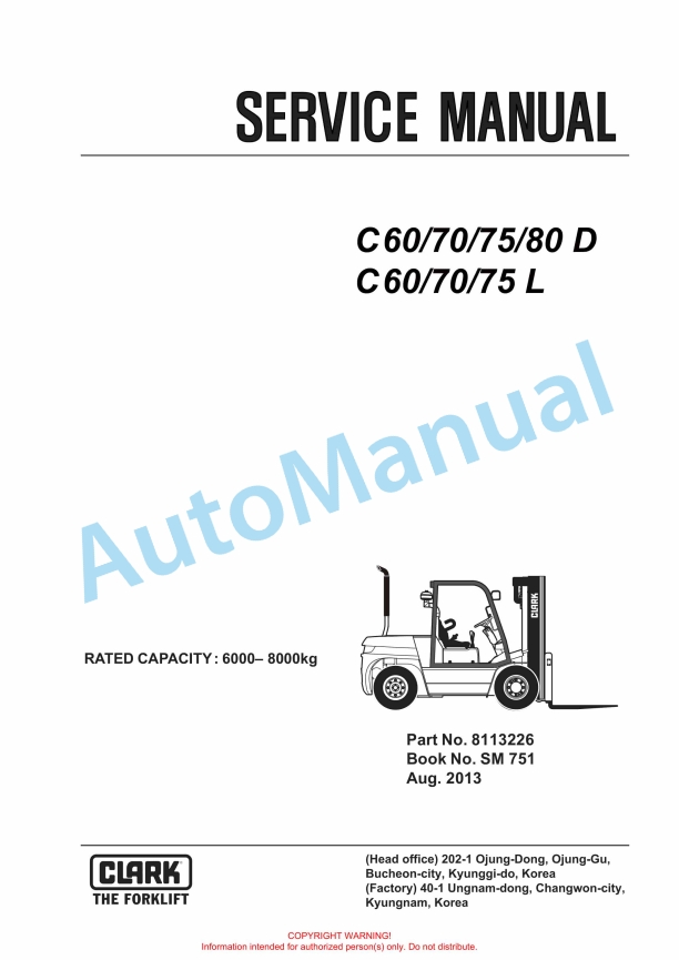
Clark C60 D, C70 D, C80 D, C80D900, C60 L, C70 L, C75 L Service Manual SM -1023
$30.00
- Type Of Manual: Service Manual
- Manual ID: SM -1023
- Format: PDF
- Size: 87.6MB
- Number of Pages: 1373
- Serial Number:
Deutz (EMR4 T4), GM (T4, T3, T0), Iveco (T3)
Category: Clark Service Manual PDF
-
Model List:
- C60 D
- C70 D
- C80 D
- C80D900
- C60 L
- C70 L
- C75 L
- 1. SM1023
- 2. CONTENTS
- 3. GROUP SA SAFE MAINTENANCE
- 3.1. Section 1 Safety
- 3.2. Section 2 Lifting, Jacking, and Blocking the Truck
- 3.3. Section 3 Towing
- 4. GROUP PS PERIODIC SERVICE
- 4.1. Section 1 Maintenance Schedules
- 4.2. Section 2 The Planned Maintenance Program
- 5. GROUP 00 (DIVECO) DIESEL ENGINE (Tier 3)
- 5.1. Section 1 GENERAL SPECIFICATIONS
- 5.2. Section 2 Fuel
- 5.3. Section 3 DUTY INDUSTRIAL APPLICATION
- 5.4. Section 4 OVERHAUL AND TECHNICAL SPECIFICATIONS
- 5.5. Section 5 TOOLS
- 5.6. Section 6 Engine Replacement
- 6. GROUP 00 (DDEUTZ) ENGINE (DEUTZ Tier 4)
- 6.1. Section 1 General
- 6.2. Section 2 Servicing and Maintenance Work
- 6.3. Section 3 Removing and Installing
- 6.4. Section 4 Special Tools
- 7. GROUP 00(L) ENGINE (GM V6 4.3L)
- 7.1. Section 1 ENGINE REMOVAL AND REPLACEMENT
- 7.2. Section 2 4.3 LITER V6 ENGINE REPAIR PROCEDURES
- 7.3. Section 3 COOLING SYSTEM
- 8. GROUP 01 ENGINE COOLING SYSTEM
- 8.1. Section 1 Engine Cooling System Specifications and Description
- 8.2. Section 2 Engine Cooling System Troubleshooting
- 8.3. Section 3 Engine Cooling System Testing and Maintenance
- 8.4. Section 4 Radiator Removal and Replacemant
- 9. GROUP 02 (LPTIER3) MI07 LP SYSTEM (GM V6 4.3)
- 9.1. Section 0 REGULATORY COMPLIANCE
- 9.2. Section 1 LPG SYSTEM OVERVIEW
- 9.3. Section 2 SPECIFICATIONS
- 9.4. Section 3 RECOMMENDED MAINTENANCE
- 9.5. Section 4 INSTALLATION PROCEDURES
- 9.6. Section 5 TESTS AND ADJUSTMENTS
- 9.7. Section 6 BASIC TROUBLESHOOTING
- 9.8. Section 7 ADVANCED DIAGNOSTICS
- 9.9. Section 8 PARTS DESCRIPTION
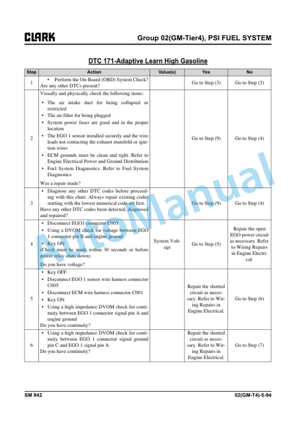
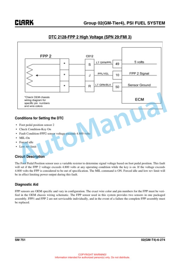
- 10. GROUP 02 (GMTIER4) PSI FUEL SYSTEM (GM V6 4.3)
- 10.1. Section 1 General Information
- 10.2. Section 2 Maintenance
- 10.3. Section 3 LPG Fuel System
- 10.4. Section 4 GASOLINE Fuel System
- 10.5. Section 5 Fuel System Diagnosis
- 10.6. Section 6 Electrical Section
- 10.7. Section 7 Definitions
- 11. GROUP 03 INTAKE AND EXHAUST SYSTEM
- 11.1. Section 1 Intake and Exhaust Systems Specifications and Description
- 11.2. Section 2 Intake System Troubleshooting
- 11.3. Section 3 Intake System Service
- 11.4. Section 4 Exhaust Systems
- 12. GROUP 07 TRANSMISSION Model 3WG94EC (for Diesel truck)
- 12.1. Section 1 LAYOUT 3WG94EC
- 12.2. Section 2 Measuring Points And Connections
- 12.3. Section 3 Disassembly
- 12.4. Section 4 Reassembly
- 12.5. Section 5 Transmission Removal and Installation
- 12.6. Section 6 AEB Setting of T/M Controller Clutch Inching Calibration
- 12.7. Section 7 Troubleshooting
- 13. GROUP 08 TRANSMISSION (T12313 MODEL) (FOR LPG TRUCK)
- 13.1. Section 1 DISASSEMBLY
- 13.2. Section 2 DISASSEMBLY AND REASSEMBLY OF 1st AND 2nd CLUTCH
- 13.3. Section 3 DISASSEMBLY AND REASSEMBLY OF 3rd CLUTCH
- 13.4. Section 4 DISASSEMBLY AND REASSEMBLY OF FORWARD AND REVERSE CLUTCHES
- 13.5. Section 5 REGULATOR VALVE DISASSEMBLY AND REASSEMBLY
- 13.6. Section 6 CLEANING AND INSPECTION
- 13.7. Section 7 TROUBLESHOOTING PROCEDURES
- 13.8. Section 8 TRANSMISSION CONTROLLER
- 13.9. Section 9 TRANSMISSION REMOVAL AND INSTALLATION
- 14. GROUP 13 ELECTRICAL SYSTEM
- 14.1. Section 1 Cautions for working on the electrical system
- 14.2. Section 2 Electrical system Specifications and features
- 14.3. Section 3 Electrical Circuit Diagram Electrical Parts Arrangement
- 14.4. Section 4 Instrument Pod
- 14.5. Section 5 Air Conditioning System (Option)
- 15. GROUP 20 (D) DRIVE AXLE (for Diesel truck)
- 15.1. Section 1 System Operation
- 15.2. Section 2 Differential Carrier Assy
- 15.3. Section 3 Drive Axle
- 15.4. Section 4 Problem and Cause
- 15.5. Section 5 Drive Axle Disassembly and Reassembly
- 15.6. Section 6 Transmission Removal and Installation
- 16. GROUP 21 (L) DRIVE AXLE (for LPG truck)
- 16.1. Section 1 System Operation
- 16.2. Section 2 Differential Carrier Assy
- 16.3. Section 3 Drive Axle
- 16.4. Section 4 Problem and Cause
- 16.5. Section 5 Disassembly and Reassembly of Drive Axle
- 16.6. Section 6 Transmission Removal and Installation
- 17. GROUP 22 WHEELS AND TIRES
- 17.1. Section 1 Wheels and Tires Specifications and Description
- 17.2. Section 2 Pneumatic Wheels and Tires
- 18. GROUP 23 BRAKE SYSTEM
- 18.1. Section 1 Braking / Inching System Specifications and Description
- 18.2. Section 2 Service Brake Troubleshooting
- 18.3. Section 3 Brake/Inching Pedals and Linkages Adjustments
- 18.4. Section 4 Brake System Bleeding
- 18.5. Section 5 Brake Valve Service
- 18.6. Section 6 Parking Brake Service
- 19. GROUP 25 STEERING COLUMN AND GEAR
- 19.1. Section 1 Steering System Specifications and Description
- 19.2. Section 2 Steering System Troubleshooting
- 19.3. Section 3 Steering Column and Component Removal and Replacement
- 19.4. Section 4 Steering System Relief Pressure Check and Adjustment
- 19.5. Section 5 Steering Gear Overhaul
- 20. GROUP 26 STEER AXLE
- 20.1. Section 1 Steer Axle Specifications and Description
- 20.2. Section 2 Steer Axle Wheel Bearing Maintenance and Adjustment
- 20.3. Section 3 Steer Axle Removal and Replacement
- 20.4. Section 4 Steer Axle Overhaul
- 20.5. Section 5 Steer Cylinder Removal and Replacement
- 20.6. Section 6 Steer Cylinder Overhaul
- 21. GROUP 29 HYDRAULIC SUMP, FILTERS, AND PUMP
- 21.1. Section 1 Main Hydraulic Sump, Filters, and Pump Specifications and Description
- 21.2. Section 2 Main Hydraulic Pump Troubleshooting
- 21.3. Section 3 Main Hydraulic Removal and Installation
- 22. GROUP 31 HYDRAULIC CONTROL VALVE
- 22.1. Section 1 Operation of Hydraulic Control Valve
- 22.2. Section 2 Hydraulic Circuit
- 22.3. Section 3 Disassembling Hydraulic Valve
- 22.4. Section 4 Assembling Hydraulic Control Valve
- 22.5. Section 5 Hydraulic System Pressure Checks and Adjustments
- 22.6. Section 6 Hydraulic Control Valve Removal and Replacement
- 22.7. Section 7 Testing Hydraulic Valve
- 22.8. Section 8 EHL Valve Disassembly and Assembly
- 23. GROUP 32 TILT CYLINDERS
- 23.1. Section 1 Tilt Cylinder Specifications and Description
- 23.2. Section 2 Tilt Cylinder Checks and Adjustments
- 23.3. Section 3 Tilt Cylinder Removal and Replacement
- 23.4. Section 4 Tilt Cylinder Overhaul
- 24. GROUP 34 UPRIGHTS
- 24.1. Section 1 Upright Specifications and Description
- 24.2. Section 2 Troubleshooting
- 24.3. Section 3 Upright Inspection
- 24.4. Section 4 Carriage and Upright Roller Clearance Checks and Shim Adjustments
- 24.5. Section 5 Cylinder Removal, Shimming, Overhaul, and Replacement
- 24.6. Section 6 Upright Chain Inspection, Adjustment, and Replacement
- 24.7. Section 7 Fork and Carriage Removal and Replacement
- 24.8. Section 8 Upright Removal and Replacement
- 25. GROUP 38 COUNTERWEIGHT AND CHASSIS
- 25.1. Section 1 Counterweight Specifications and Description
- 25.2. Section 2 Counterweight Removal and Replacement
- 25.3. Section 3 Overhead Guard/Operators Cell Removal and Replacement
- 25.4. Section 4 Floorboard, Cowls, and Seat Deck Removal and Replacement
- 25.5. Section 5 Operators Seat Removal and Replacement
- 26. GROUP 40 SPECIFICATIONS
- 26.1. Section 1 Nameplates and Decals
- 26.2. Section 2 General Specifications
- 26.3. Section 3 Hydraulic Fitting Tightening Procedure
Rate this product
You may also like
Clark Service Manual PDF
Clark C 15s L, C 18s L, C 20s L, C 15sC L, C 18sC L, C 20sC L Service Manual SM-995
$30.00
Clark Service Manual PDF
Clark C500-355, C500-H355, C500-Y355, C500-HY355 Gasoline, LPG Service Manual SM-333
$30.00
Clark Service Manual PDF
Clark C 40, 45, 50s, 55s D, C 40, 45, 50s, 55s L Service Manual SM-942
$30.00
Clark Service Manual PDF
Clark C20, 25, 30, 35 D, L, G, C20, 25, 30, 32C L Service Manual SM-996
$30.00
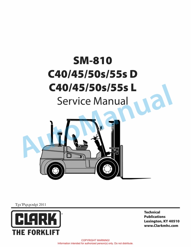
Clark Service Manual PDF
Clark C40, 45, 50s, 55s D, C40, 45, 50s, 55s L Service Manual SM-810
$30.00
- Claas
- Grove
- New Holland
- Komatsu
- Kubota
- John Deere
- Linde
- Bomag
- CASE
- Clark
- JCB
- Jungheinrich
- Linde
- Yale
- Yanmar
- Manitou
- Manitowoc
- CNH
- Doosan
- Fiatagri
- Fiatallis
- Fiatallis Other Manual PDF
- Flexi Coil
- Ford New Holland
- Ford New Holland Other Manual PDF
- Huyndai
- Hypac
- Hyster
- Hyster Service Manual PDF
- Isuzu
- Kobelco
- Kohler
- Krupp
- Lombardini
- Mahindra
- Nuvera
- Perkins
- Sperry New Holland
- Utilev
- Versatile
- ZF