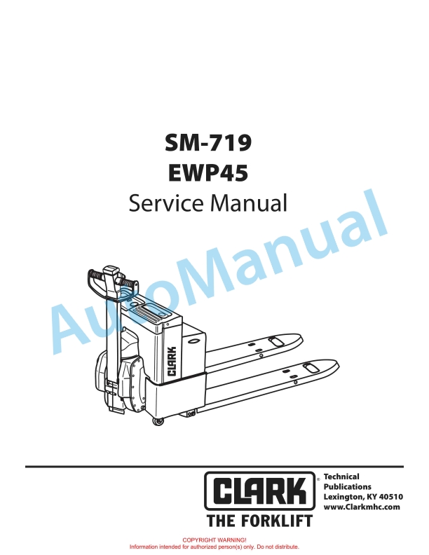
Clark EWP45 Service Manual SM-719
$30.00
- Type Of Manual: Service Manual
- Manual ID: SM-719
- Format: PDF
- Size: 3.0MB
- Number of Pages: 178
Category: Clark Service Manual PDF
-
Model List:
- EWP45
- 1. IMPORTANT SAFETY NOTICE
- 2. Arrangement and Use of this Manual
- 3. Contents by Section
- 4. Section Locations
- 5. INTRODUCTION
- 5.1. Truck Presentation.
- 5.2. Truck Side Views
- 5.3. Intended Truck Application
- 5.4. Prohibited Truck Application
- 5.5. Truck Data
- 5.6. Truck Dimensions
- 5.7. Data Plate
- 5.8. Reverser switch
- 5.9. Travel speed/direction selection
- 5.10. Horn switch
- 5.11. Fork raise switch
- 5.12. Fork lower switch
- 5.13. Battery
- 5.14. Load wheel
- 5.15. Drive unit with brake
- 5.16. Electric panel
- 5.17. Circuit breaker
- 5.18. Steering pivot point
- 5.19. Hydraulic unit
- 5.20. Hydraulic electric solenoid valve
- 5.21. Steering control handle
- 5.22. Key switch (toggle switch)
- 5.23. Emergency Disconnect Switch
- 5.24. Battery Receptacle
- 6. GROUP PS PERIODIC SERVICE
- 6.1. SECTION 1 Maintenance ScheduleE
- 6.1.1. Periodic Service and Planned Maintenance
- 6.1.2. Determining Maintenance Intervals
- 6.1.3. CHECK SHEET
- 6.1.4. Visual Inspection
- 6.1.5. Operational Tests
- 6.1.6. Lubrication Chart
- 6.1.7. Oil and Grease Specifi cations
- 6.1.8. Jacking Truck Off the Floor
- 6.2. SECTION 2 The PM Inspection Form
- 6.2.1. PM Report Form
- 7. GROUP 12 BATTERY
- 7.1. SECTION 1 Battery
- 7.1.1. Battery Handling
- 7.1.1.1. Keeping Battery Records
- 7.1.1.2. Install Battery
- 7.1.1.3. REPLACEMENT BATTERIES
- 7.1.1.4. Clean Battery Compartment
- 7.1.1.5. Battery Electrolyte
- 7.1.1.6. Battery Charging
- 7.1.1.7. Battery Maintenance
- 7.1.1.8. Battery Cleaning
- 7.1.1.9. Battery Vents
- 7.1.1.10. Battery Removal
- 7.1.2. Swing Out Battery Pack
- 7.1.3. Battery Cable Routing Diagram
- 7.1.4. Battery Connector
- 7.1.5. Battery Controller/Hourmeter
- 7.1.6. Battery Safety
- 7.1.7. Battery
- 7.1.8. Battery Maintenance
- 7.1.9. Storage
- 7.1.10. Charger Diagram
- 7.1.11. Troubleshooting
- 7.1.12. Electrical
- 7.1.13. Pilot Cell
- 8. GROUP 13 ELECTRICAL CONTROLS
- 8.1. SECTION 1 Electrical Controls
- 8.2. Directional Control Housing
- 8.3. Driver Protection (Reverser) Assembly
- 8.4. Direction Control Switches
- 8.5. Raise, Lower, and Horn Switches
- 8.6. Potentiometer
- 9. GROUP 14 ELECTRICAL
- 9.1. Electrical Functions
- 9.2. Electrical Panel Components
- 9.3. Wiring Schematic
- 9.4. Start / Stop Switches
- 10. GROUP 16 ELECTRIC MOTORS
- 10.1. General Information
- 10.2. Pump Motor
- 10.3. Inspection and Troubleshooting
- 10.4. Brush Inspection
- 10.5. Drive Motor Brush
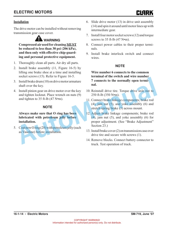
- 10.6. Drive Motor Removal
- 10.7. Component Repair
- 10.8. Motor Disassembly
- 10.9. Motor Inspection
- 10.10. Assembly/Testing
- 11. GROUP 19 MOTOR CONTROLS
- 11.1. OVERVIEW
- 11.2. CONNECTIONS
- 11.3. PROGRAMMER MENUS
- 11.4. PROGRAM MENU
- 11.5. MONITOR MENU
- 11.6. SYSTEM FAULTS MENU
- 11.7. DIAGNOSTICS AND TROUBLESHOOTING
- 11.7.1. Troubleshooting Chart
- 11.8. STATUS LED DIAGNOSTICS
- 11.9. CONTROLLER MAINTENANCE
- 11.10. VEHICLE DESIGN CONSIDERATIONS
- 11.11. ELECTROSTATIC DISCHARGE (ESD)
- 11.12. HANDHELD PROGRAMMER
- 12. GROUP 20 DRIVE UNIT
- 12.1. System Description
- 12.2. Troubleshooting
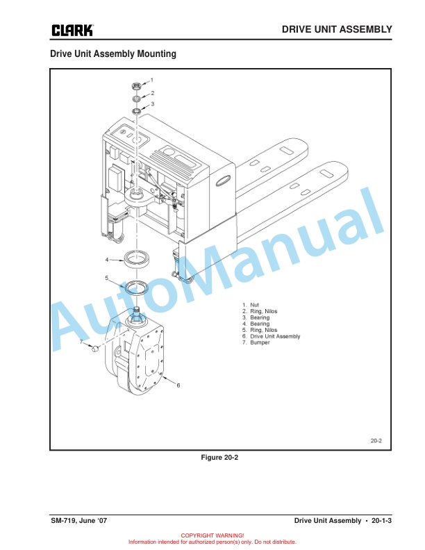
- 12.3. Drive Unit Assembly Mounting
- 12.4. Drive Unit Repair
- 12.4.1. Disassembly
- 12.4.2. Reassembly
- 12.5. Axle Seal
- 13. GROUP 23 BRAKE SYSTEM
- 13.1. Brake Theory of Operation
- 13.2. Brake System
- 13.3. Brake Adjustment
- 13.4. Brake Shoe Removal / Installation
- 13.5. Brake Switch
- 13.6. Drive Wheel
- 14. GROUP 25 CASTER ASSEMBLY
- 15. GROUP 26 STEERING
- 15.1. Steering Stem
- 16. GROUP 30 HYDRAULICS
- 16.1. General
- 16.2. Adjustments
- 16.3. Installation
- 16.4. Assembly
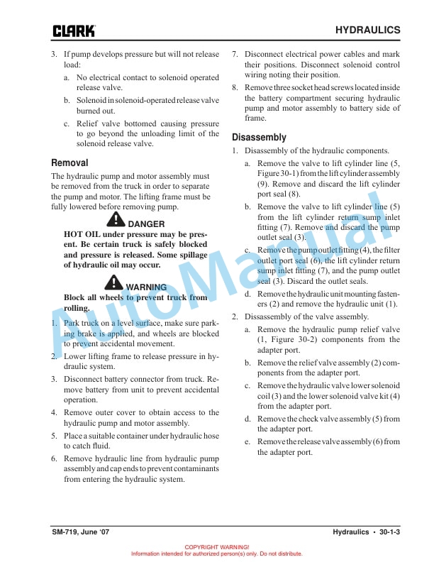
- 16.5. Disassembly
- 16.6. Removal
- 16.7. Troubleshooting
- 17. GROUP 34 LIFT CYLINDER
- 17.1. Lift Cylinder Removal
- 17.2. Installation
- 18. GROUP 35 LIFT LINKAGE
- 18.1. Operational Check
- 18.2. Bearing Identifi cation
- 18.3. Lift Linkage Removal
- 18.3.1. Separate Lift Frame from Main Frame
- 18.3.2. Elevate and block truck as shown
- 18.3.3. Block Lift Frame and Main Frame
- 18.3.4. Remove Cylinder Pivot Shaft
- 18.3.5. Remove Upper Link Arms
- 18.3.6. Remove Left and Right Lower Link Arms
- 18.3.7. Disconnect Load Wheel Bracket
- 18.3.8. Bearing Removal
- 18.3.9. Cleaning and Inspections
- 18.3.10. Bearing Installation
- 18.4. Bearing Press Specifi cations
- 18.5. Lower Link Arms
- 18.6. Load Wheels
- 19. GROUP 39 SHEET METAL
- 20. GROUP 40 TRUCK SPECIFICATIONS
Rate this product
You may also like
Clark Service Manual PDF
Clark C500-355, C500-H355, C500-Y355, C500-HY355 Gasoline, LPG Service Manual SM-333
$30.00
Clark Service Manual PDF
Clark C20, 25, 30, 35 D, L, G, C20, 25, 30, 32C L Service Manual SM-996
$30.00
Clark Service Manual PDF
Clark C40, 45, 50s, 55s D, C40, 45, 50s, 55s L Service Manual SM-810
$30.00

