


Clark Service Manual PDF
Clark C40, 45, 50s, 55s D, C40, 45, 50s, 55s L Service Manual SM-810
$30.00
Clark Service Manual PDF
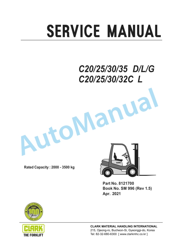
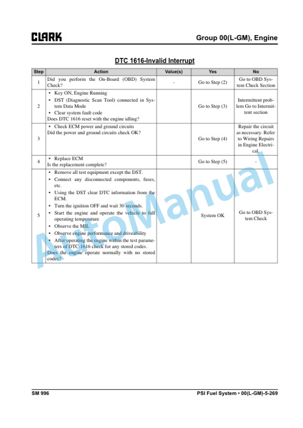
Clark C20, 25, 30, 35 D, L, G, C20, 25, 30, 32C L Service Manual SM-996
$30.00
Clark Service Manual PDF
$30.00
Clark Service Manual PDF
Clark C15s D-L, C 18s D-L, C 20s D-L, C15s C-L, C 18s C-L, C 20s C-L Service Manual SM-1066
$30.00
Clark Service Manual PDF
Clark C 20, 25, 30, 35 L-G, C 20, 25, 30, 32C L Service Manual SM-1044
$30.00