


Clark Service Manual PDF
Clark C40, 45, 50s, 55s D, C40, 45, 50s, 55s L Service Manual SM-810
$30.00
Clark Service Manual PDF
$30.00
Clark Service Manual PDF
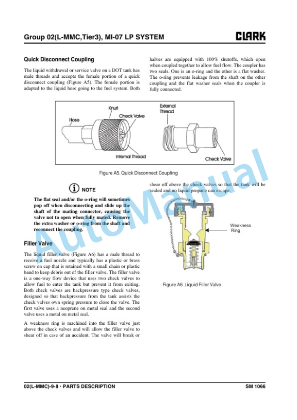
Clark C15s D-L, C 18s D-L, C 20s D-L, C15s C-L, C 18s C-L, C 20s C-L Service Manual SM-1066
$30.00
Clark Service Manual PDF
Clark C500-355, C500-H355, C500-Y355, C500-HY355 Gasoline, LPG Service Manual SM-333
$30.00