Clark WP45 Service Manual SM-698
$30.00
- Type Of Manual: Service Manual
- Manual ID: SM-698
- Format: PDF
- Size: 9.4MB
- Number of Pages: 280
Category: Clark Service Manual PDF
-
Model List:
- WP45
- 1. Standard Codes
- 2. Table of Contents
- 3. Warning Symbols
- 4. Prohibitory Symbols
- 5. Battery Safety
- 6. Static Safety
- 7. Welding Safety
- 8. Service Manual Introduction
- 9. Contents, Section M
- 9.1. Machine Information
- 9.1.1. General Product Information
- 9.1.1.1. Truck Presentation.
- 9.1.2. Main Components
- 9.1.3. Inch and Metric (SAE) Fasteners
- 9.1.3.1. Introduction
- 9.1.3.2. Nomenclature, Threads
- 9.1.3.3. Strength Identification
- 9.1.3.4. Conversion of English and Metric Units
- 9.1.4. Technical Service Data
- 9.1.5. Ordering Spare Parts
- 10. Contents, Section P
- 10.1. Planned Maintenance
- 10.1.1. Introduction, Maintenance
- 10.1.1.1. Jacking Truck Off The Floor
- 10.1.1.2. Lubricants
- 10.1.2. Service Schedule
- 10.1.2.1. Planned Maintenance Schedule
- 10.1.2.2. Planned Maintenance Procedures
- 10.1.2.3. Services Performed Every 480 or 960 Operating Hours
- 10.1.2.4. Services Performed Annually or Every 1440 Operating Hours
- 10.1.3. Lubrication Chart
- 10.1.4. Oil and Grease Specifications
- 10.1.4.1. Approved Oils and Grease
- 10.1.4.2. Grease Location Points
- 11. Contents, Section S
- 11.1. Service Instructions
- 11.2. Chassis/Lift Frame
- 11.2.1. Pull rod
- 11.2.1.1. Removal
- 11.2.1.2. Inspection
- 11.2.1.3. Installation
- 11.2.2. Carrier Frame Bushings
- 11.3. Inspection Covers
- 11.3.1. General Information
- 11.4. Driver Controls
- 11.4.1. Decal with Protective Sheet
- 11.4.2. Decal without Protective Sheet
- 11.5. Motor Maintenance Schedule/ Troubleshooting
- 11.5.1. General Information
- 11.5.2. Operating Conditions
- 11.5.3. Troubleshooting
- 11.6. Pump Motor
- 11.6.1. Mounting Points
- 11.6.1.1. Removal
- 11.6.1.2. Installation
- 11.6.2. Pump Motor Repair
- 11.6.2.1. Disassembly
- 11.6.3. Inspection and Troubleshooting
- 11.6.3.1. Drive End Head
- 11.6.3.2. Commutator End Head
- 11.6.3.3. Bearings
- 11.6.4. Brush Inspection
- 11.6.4.1. Brush Replacement Determination
- 11.6.4.2. Replacement Procedures
- 11.7. Drive Motor
- 11.7.1. Mounting Points
- 11.7.1.1. Drive Motor Brush
- 11.7.1.2. Drive Motor Removal
- 11.7.1.3. Drive Motor Installation
- 11.7.2. Component Repair
- 11.7.2.1. Motor Disassembly
- 11.7.3. Motor Inspection
- 11.7.3.1. External Motor
- 11.7.3.2. Brush and Commutator
- 11.7.3.3. Bearings
- 11.7.3.4. Armature Electrical Check
- 11.7.3.5. Frame and Field Service Recommendation
- 11.7.3.6. Assembly/Testing
- 11.8. Transmission
- 11.8.1. System Description
- 11.8.2. Troubleshooting
- 11.8.3. Transmission Mounting
- 11.8.3.1. Wrap Around Bumper
- 11.8.3.2. Removal
- 11.8.3.3. Installation
- 11.8.4. Transmission Repair
- 11.8.4.1. Disassembly
- 11.8.4.2. Reassembly
- 11.8.5. Axle Seal
- 11.8.5.1. Removal
- 11.8.5.2. Installation
- 11.9. Parking Brake System
- 11.9.1. Brake Theory of Operation
- 11.9.2. Brake Adjustment
- 11.9.3. Brake Shoe Removal / Installation
- 11.10. Drive Wheel
- 11.10.1. Removal
- 11.10.2. Installation
- 11.10.3. Tire Pressing Procedure
- 11.11. Support/Swivel Wheel (Optional)
- 11.11.1. Maintenance and Adjustments
- 11.11.1.1. Caster Adjustment
- 11.11.2. Troubleshooting
- 11.11.2.1. Stabilizing Caster
- 11.12. Fork Wheels
- 11.12.1. Removal/Installation
- 11.13. Steering
- 11.13.1. Control Handle Head
- 11.13.1.1. Removal
- 11.13.1.2. Installation
- 11.13.2. Driver Protection (Reverser) Assembly Replacement
- 11.13.3. Direction Control Switches
- 11.13.3.1. Removal
- 11.13.3.2. Installation
- 11.13.4. Raise, Lower, and Horn Switches
- 11.13.4.1. Removal
- 11.13.4.2. Installation
- 11.13.5. Potentiometer
- 11.13.5.1. Removal
- 11.13.5.2. Installation
- 11.13.6. Steering Stem
- 11.13.6.1. Removal
- 11.13.6.2. Installation
- 11.14. Electrical Functions
- 11.14.1. General
- 11.14.1.1. Adjustable Settings
- 11.14.1.2. References
- 11.14.1.3. Key Switch S17 in the ON Position
- 11.14.1.4. Operating Arm in Drive Position, S10, Brake Switch Closed
- 11.14.1.5. Travel Request, Fork First
- 11.14.1.6. Travel Request, Forks Trailing
- 11.14.1.7. Reversing/Motor Brake Forks First Direction to Forks Trailing Direction
- 11.14.1.8. Reversing/Motor Brake Forks Trailing Direction to Forks First Direction
- 11.14.1.9. Reverser switch
- 11.14.1.10. Lifting Forks
- 11.14.1.11. Lowering Forks
- 11.14.1.12. Lift Interrupt
- 11.15. Electrical Panel Components
- 11.16. Electrical Symbols
- 11.17. Electrical Schematics
- 11.18. Battery
- 11.18.1. Removal
- 11.18.2. Installation
- 11.18.3. Battery Maintenance
- 11.18.3.1. Battery Inspection and Care
- 11.18.3.2. Battery Exterior Cleaning
- 11.18.3.3. Charging
- 11.18.4. Storage
- 11.18.5. Battery History Record
- 11.19. Swing Out Battery Pack
- 11.19.1. Battery Cable Routing Diagram
- 11.19.2. Charger Diagram
- 11.19.3. Troubleshooting
- 11.19.3.1. Electrical Testing
- 11.19.3.2. Equipment required
- 11.19.3.3. Instructions
- 11.20. Battery Connector
- 11.20.1. Location
- 11.20.2. Inspection
- 11.20.3. Installation
- 11.21. Battery Controller/Hourmeter/ Lift Interrupt (Optional)
- 11.21.1. General Information
- 11.21.2. Electrical
- 11.21.2.1. Voltage
- 11.21.3. Battery Controller (BC)
- 11.21.3.1. General Information
- 11.21.3.2. Key Switch
- 11.21.3.3. Hourmeter
- 11.21.4. Troubleshooting
- 11.21.4.1. Battery Discharge Indicator (BDI)
- 11.21.4.2. Hourmeter
- 11.22. Battery Discharge Indicator / Hourmeter
- 11.22.1. General Information
- 11.22.2. Electrical
- 11.22.2.1. Voltage
- 11.22.3. Battery Discharge Indicator (BDI)
- 11.22.3.1. General Information
- 11.22.3.2. Key Switch
- 11.22.3.3. Hourmeter
- 11.22.4. Troubleshooting
- 11.22.4.1. Battery Discharge Indicator (BDI)
- 11.22.4.2. Hourmeter
- 11.23. Start/Stop Switches
- 11.23.1. General
- 11.23.1.1. Test/Inspection
- 11.23.2. Master Control On/Off Switch (S21)
- 11.23.2.1. Inspection
- 11.23.2.2. Removal
- 11.23.2.3. Installation
- 11.24. Transistor Controller
- 11.24.1. Basics Of Circuit Operation
- 11.24.1.1. Control Features
- 11.24.2. Maintenance
- 11.24.2.1. Cleaning
- 11.24.3. Motor Circuit
- 11.24.4. Control Circuit
- 11.24.5. Troubleshooting Guidelines
- 11.24.5.1. General
- 11.24.6. Shorts to Frame Test
- 11.24.7. Definitions
- 11.24.8. Diagnostics and Troubleshooting
- 11.24.8.1. Handset Diagnostics
- 11.24.8.2. Troubleshooting
- 11.24.8.3. Troubleshooting Chart
- 11.24.8.4. Technical Specification
- 11.24.8.5. Troubleshooting Chart Using Handset
- 11.25. Transistor Controller Troubleshooting
- 11.25.1. Troubleshooting Chart Index
- 11.25.2. Troubleshooting Charts
- 11.25.2.1. Special Instructions
- 11.26. Hydraulic System
- 11.26.1. General
- 11.26.2. Troubleshooting
- 11.26.3. Schematic
- 11.26.4. Description
- 11.26.4.1. Relief Pressure
- 11.26.5. Maintenance
- 11.26.6. Lift Limit Switch
- 11.27. Hydraulic Pump
- 11.27.1. Removal
- 11.27.2. Disassembly
- 11.27.3. Inspection
- 11.27.4. Reassembly
- 11.27.5. Installation
- 11.27.6. Adjustments
- 11.27.6.1. Relief valve
- 11.27.6.2. Solenoid Operated Valve
- 11.28. Lift Cylinder
- 11.28.1. Cylinder Repair
- 11.28.1.1. Removal
- 11.28.1.2. Disassembly
- 11.28.1.3. Inspection
- 11.28.1.4. Assembly
- 11.28.1.5. Installation
- 11.29. Battery Charger, Optima Pack
- 11.29.1. Battery Charger Wiring Diagram Optima Pack
- 11.30. Handset Operation
- 11.30.1. Operating Modes
- 11.30.2. Revert to Previous Settings
- 11.30.3. Handset Self Test
Rate this product
You may also like
Clark Service Manual PDF
Clark C 40, 45, 50s, 55s D, C 40, 45, 50s, 55s L Service Manual SM-942
$30.00
Clark Service Manual PDF
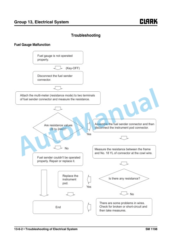
Clark C 15s L, C 18s L, C 20s L, C 15sC L, C 18sC L, C 20sC L Service Manual SM-1198
$30.00
Clark Service Manual PDF
$30.00
Clark Service Manual PDF
$30.00