 Maintenance Schedule 1")
 Maintenance Schedule 2")
 Maintenance Schedule 3")
 Maintenance Schedule 4")
 Maintenance Schedule 5")
Hyster C098 (E3.50-5.50XL, E4.50XLS) Maintenance Schedule
$30.00
- Type Of Manual: Maintenance Schedule
- Number of Pages: 919
- Size: 29.9MB
- Format: PDF
Category: Hyster Service Manual PDF
-
Model List:
- C098 (E3.50-5.50XL, E4.50XLS)
- 1. RM0291-(12-1993)-UK-EN
- 1.1. INTRODUCTION
- 1.2. MAINTENANCE SCHEDULE
- 1.3. MAINTENANCE PROCEDURES EVERY 8 HOURS OR DAILY
- 1.4. EVERY 350 HOURS OR TWO MONTHS
- 1.5. EVERY 2000 HOURS OR YEARLY
- 1.6. GENERAL PROCEDURES
- 1.7. WHEELS AND TIRES
- 1.8. SPECIFICATIONS
- 1.9. REFERENCE TABLE
- 2. RM0284-(10-2002)-UK-EN
- 2.1. Safety Precautions Maintenance and Repair
- 2.2. General
- 2.3. Description
- 2.4. Overhead Guard Repair
- 2.5. Install
- 2.6. Battery Restraint and Seat Assembly Repair
- 2.7. Seat Brake Assembly E/J1.25-3.00XL (E/J25-60XL), Adjust
- 2.8. Seat Brake Assembly E3.50-5.50XL (E70-120XL), Adjust
- 2.9. Counterweight Repair
- 2.10. Install
- 2.11. Traction Motor Repair
- 2.12. Install
- 2.13. Hydraulic Tank Repair
- 2.14. Inspect
- 2.15. Small Leaks, Repair
- 2.16. Large Leaks, Repair
- 2.17. Steam Method
- 2.18. Chemical Solution Method
- 2.19. Additional Preparations For Repair
- 2.20. Painting Instructions
- 2.21. Safety Label Replacement
- 2.22. Table 1. Battery Specifications (Battery without Cover)
- 2.23. Table 2. Battery Specifications (Battery with Flat Cover)
- 2.24. Table 3. Battery Specifications (Battery with Dome Cover)
- 2.25. Table 4. Battery Specifications
- 2.26. Table 5. Seat Brake Adjustment
- 2.27. Table 6. Counterweights
- 3. RM0286-(07-2000)-UK-EN
- 3.1. HYDRAULIC SYSTEM
- 3.2. REPAIRS
- 3.3. CHECKS AND ADJUSTMENTS
- 3.4. TROUBLESHOOTING
- 3.5. SPECIFICATIONS
- 4. RM0294-(03-2008)-UK-EN
- 4.1. General
- 4.2. Brush and Commutator Inspection
- 4.3. Brush Replacement
- 4.4. Stoning the Commutator
- 4.5. Motors Repair
- 4.6. Brush Alignment, Traction and Hydraulic Motors
- 4.7. Tests for Damaged Field and Armature
- 4.8. Troubleshooting
- 5. RM0326-(03-2007)-UK-EN
- 5.1. General
- 5.2. Description
- 5.3. Steering Axle Assembly Repair
- 5.4. Wheels and Hubs Repair (All Units)
- 5.5. Spindles and Bearings Repair (All Units)
- 5.6. Tie Rods Repair (All Units)
- 5.7. Steering Cylinder Repair
- 5.8. Troubleshooting
- 6. RM0338-(05-2009)-UK-EN
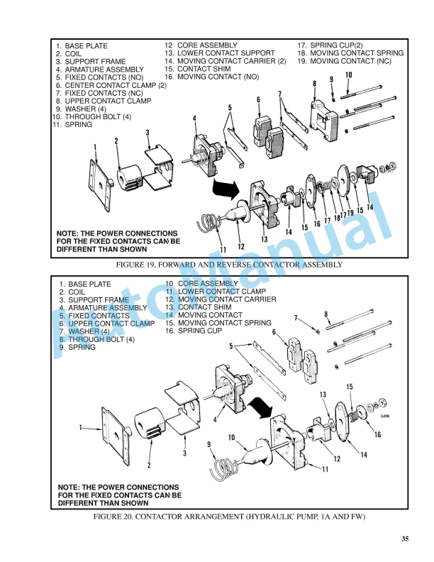
- 6.1. Brake System
- 6.2. Safety Precautions Maintenance and Repair
- 6.3. General
- 6.4. Description and Operation
- 6.5. Brake Booster and Master Cylinder
- 6.6. Master Cylinder
- 6.7. Service Brake Assembly
- 6.8. Parking Brake
- 6.9. Seat Brake
- 6.10. Brake Shoe Assemblies Repair
- 6.11. Remove and Disassemble
- 6.12. Clean and Inspect
- 6.13. Assemble and Install
- 6.14. Master Cylinder Repair
- 6.15. Master Cylinder For Lift Truck Models S3.50-5.50XL (S70-120XL) (
- 6.16. Disassemble
- 6.17. Assemble
- 6.18. Install
- 6.19. Master Cylinder For Lift Truck Models E3.50-5.50XL (E70-120XL, E
- 6.20. Remove and Disassemble
- 6.21. Clean and Inspect
- 6.22. Assemble and Install
- 6.23. Brake Booster Repair
- 6.24. Disassemble
- 6.25. Clean and Inspect
- 6.26. Assemble
- 6.27. Install
- 6.28. Brake System Air Removal
- 6.29. Brake Pedal Adjustment
- 6.30. Brake Pedal for Lift Truck Models H3.50-5.00XL (H70-110XL) (F005
- 6.31. Brake Shoes Adjustment
- 6.32. Parking Brake Adjustment
- 6.33. Parking Brake Adjustment, Lift Truck Models S3.50-5.50XL (S70-12
- 6.34. Parking Brake Lever and Switch Adjustment E3.50-5.50XL (E70-120X
- 6.35. Seat Brake Assembly
- 6.36. Clean and Inspect
- 6.37. Install
- 6.38. Adjustments
- 6.39. Solenoid Adjustment
- 6.40. Traction cutoff Switch Adjustment
- 6.41. Cable Adjustment
- 6.42. Brake Booster Relief Valve Check
- 6.43. Troubleshooting
- 7. RM0340-(09-2002)-UK-EN
- 7.1. Vista Masts
- 7.2. Safety Precautions Maintenance and Repair
- 7.3. General
- 7.4. Description and Operation
- 7.5. Carriages
- 7.6. Two-Stage Mast With Limited Free-Lift
- 7.7. Two-Stage Mast With Full Free-Lift Mast
- 7.8. Three-Stage Mast With Full Free-Lift
- 7.9. Safety Procedures When Working Near Mast
- 7.10. Forks Replacement
- 7.11. Remove and Install
- 7.12. Hook Fork
- 7.13. Pin Fork
- 7.14. Carriage Repair
- 7.15. Sideshift Carriage Repair
- 7.16. Sideshift Carriage (Earlier Designs)
- 7.17. Disassemble
- 7.18. Assemble
- 7.19. Install
- 7.20. Sideshift Carriage (1993 and Later Design)
- 7.21. Repairs
- 7.22. Install
- 7.23. Weight of Mast Parts
- 7.24. Two-Stage Mast With Limited Free-Lift Repair
- 7.25. Disassemble
- 7.26. Clean and Inspect
- 7.27. Assemble
- 7.28. Install
- 7.29. Two-Stage Mast With Full Free-Lift Repair
- 7.30. Disassemble
- 7.31. Clean and Inspect
- 7.32. Assemble
- 7.33. Install
- 7.34. Three-Stage Mast With Full Free-Lift
- 7.35. Disassemble
- 7.36. Clean and Inspect
- 7.37. Assemble
- 7.38. Install
- 7.39. Mast Operation Check
- 7.40. Lift and Tilt System Leak Check
- 7.41. Lift System
- 7.42. Tilt System
- 7.43. Tilt Cylinder Stroke and Backward Tilt Angle Adjustment
- 7.44. Lift Chain Adjustments
- 7.45. Mast Adjustments
- 7.46. Carriage Adjustment
- 7.47. Troubleshooting
- 8. RM0413-(11-2006)-UK-EN
- 8.1. Drive Axle, Speed Reducer, and Differential
- 8.2. Safety Precautions Maintenance and Repair
- 8.3. General
- 8.4. Description
- 8.5. Drive Axle, Speed Reducer, and Differential Repair
- 8.6. General
- 8.7. Traction Motor, Speed Reducer, and Differential
- 8.8. Disassemble
- 8.9. Speed Reducer
- 8.10. Differential
- 8.11. Inspect
- 8.12. Assemble
- 8.13. Speed Reducer
- 8.14. Differential
- 8.15. Drive Axle Housing
- 8.16. Inspect
- 8.17. Assemble
- 8.18. Troubleshooting
- 8.19. Table 1. Pinion Assembly Shims Adjustment
- 8.20. Table 2. Ring and Pinion Tooth Contact Adjustment
- 9. RM0485-(07-2000)-UK-EN
- 9.1. STEERING SYSTEMS FOR ELECTRICAL LIFT TRUCKS
- 9.2. POWER STEERING MOTOR AND PUMP
- 9.3. HYDRAULIC STEERING MOTOR
- 9.4. CHECKS AND ADJUSTMENTS
- 9.5. TROUBLESHOOTING
- 10. RM0560-(07-2005)-UK-EN
- 10.1. Electrical System
- 10.2. Safety Precautions Maintenance and Repair
- 10.3. General
- 10.4. Description
- 10.5. ZX Series Display Panels
- 10.6. Display Panel
- 10.7. Basic Display Panels
- 10.8. Performance Display
- 10.9. Brush Wear Indicators
- 10.10. SEM Display Panels – Features
- 10.11. Descriptions of Common Features
- 10.12. Additional Features of Premium Display Panel
- 10.13. Descriptions of Additional Features
- 10.14. SEM Display Panel Indicators
- 10.15. All Indicator Symbols
- 10.16. Hourmeter Indicator Symbol
- 10.17. Wrench Symbol
- 10.18. Battery Symbol
- 10.19. Battery Discharge Indicator (BDI)
- 10.20. Brake Fluid Too Low Symbol
- 10.21. Parking Brake Symbol
- 10.22. Fasten Seat Belt Symbol
- 10.23. LCD Screen (Standard Display Panel)
- 10.24. Additional Components of Premium Display Panel
- 10.25. Alpha Numerical Screen
- 10.26. STAR Push Button
- 10.27. Push Buttons 1 Through 5 – SEM
- 10.28. Other Control Components
- 10.29. Display Panel Components Replacement
- 10.30. ZX Panel Replacement
- 10.31. Display Panel Assembly
- 10.32. Key Switch, Replace
- 10.33. Indicator LEDs
- 10.34. Battery Indicators
- 10.35. Digital Display (Performance Display Panel Only)
- 10.36. Status Code or Performance Level Switches and Indicator LEDs (Pe
- 10.37. Basic Display Panel, Replace Parts
- 10.38. Performance Display Panel, Replace Parts
- 10.39. SEM Display Panel Replacement
- 10.40. Motor Controller (SR or SP) Replacement
- 10.41. Install
- 10.42. Control Components Replacement
- 10.43. Start Switch, Replace
- 10.44. Brake Light Switch, Replace
- 10.45. Seat Switch, Replace
- 10.46. External Seat Switch, Adjust
- 10.47. Switch for Optional Seat Brake, Replace
- 10.48. Parking Brake Switch, Replace
- 10.49. Direction Switches (MONOTROL Pedal), Replace
- 10.50. Direction Control Switches (Steering Column), Replace
- 10.51. Direction Control Switches, E70-120XL 3 (Steering Column)
- 10.52. Brake Fluid Switch, Replace
- 10.53. Brush Wear and Overtemperature Sensors
- 10.54. Rocker Switches for Lights
- 10.55. Accelerator Position Sensor, Replace
- 10.56. On-Demand Steering Components
- 10.57. Lights, Converter, Relay, and Reverse Alarm
- 10.58. Incandescent Brake, Tail, and Reverse Light Assembly, Replace
- 10.59. LED Brake, Tail, and Reverse Light Assembly, Replace
- 10.60. Flashing Light Assembly, Replace
- 10.61. Front, Rear Driving Light, or Spot Light Assemblies, Replace
- 10.62. Operator Compartment Light Assembly, Replace
- 10.63. Converter, Replace
- 10.64. Relay, Replace
- 10.65. Reverse Alarm, Replace
- 10.66. Horn and Horn Button
- 10.67. Horn Switch and Cover
- 10.68. Hydraulic Pump Switches
- 10.69. Control and Power Fuses Check
- 10.70. ZX Motor Controllers
- 10.71. SEM Motor Controllers
- 10.72. SEM Controller Field Diagnostic Procedure
- 10.73. Armature FET Test
- 10.74. Field FET Test
- 10.75. Brush Wear and Overtemperature Sensors Check – ZX Motor Controll
- 10.76. Thermal Sensors – SEM Motor Controllers Check
- 10.77. Start Switch Adjustment
- 10.78. Accelerator Potentiometer and Start Switch, E70-120XL, E70-120XL
- 10.79. E70-120XL
- 10.80. E70-120XL 3
- 10.81. Direction Switches (MONOTROL)
- 10.82. Brake Light Switch Adjustment
- 10.83. Seat Switch Check
- 10.84. Optional Seat Brake Switch Adjustment
- 10.85. Parking Brake Switch Adjustment
- 10.86. Direction Switches Check
- 10.87. Monotrol Pedal
- 10.88. Steering Column
- 10.89. Hydraulic Pump Switch Adjustment
- 10.90. MONOTROL or Accelerator Pedal Adjustment
- 10.91. Accelerator Position Sensor Adjustment
- 11. RM0001-(01-2016)-UK-EN
- 11.1. General
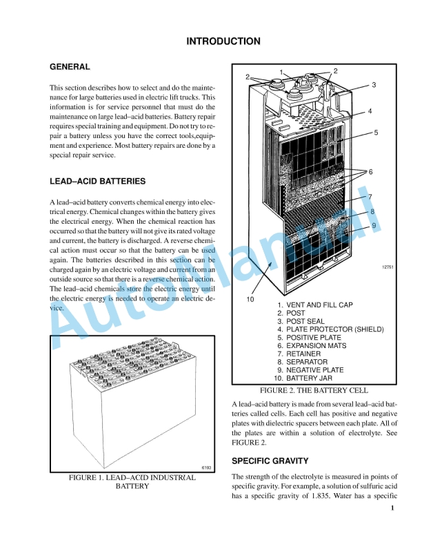
- 11.2. Lead-Acid Batteries
- 11.3. Specific Gravity
- 11.4. Chemical Reaction in a Cell
- 11.5. Electrical Terms
- 11.6. Battery Selection
- 11.7. Battery Voltage
- 11.8. Battery as a Counterweight
- 11.9. Battery Ratings
- 11.10. Battery Maintenance
- 11.11. Troubleshooting
- 12. RM0145-(02-1997)-UK-EN
- 12.1. INTRODUCTION
- 12.2. MAGNETISM
- 12.3. BASIC MOTORS
- 13. RM0077-(02-2009)-UK-EN
- 13.1. Manual hydraulic Control Valve
- 13.2. Safety Precautions Maintenance and Repair
- 13.3. General
- 13.4. Description
- 13.5. Operation
- 13.6. Lift Section
- 13.7. Tilt Section
- 13.8. Tilt Backward
- 13.9. Tilt Forward
- 13.10. Relief Valve
- 13.11. Solenoid Valve for Auxiliary Function
- 13.12. Main Control Valve Repair
- 13.13. Remove and Disassemble – Control Valve Without OPS Solenoid
- 13.14. Remove and Disassemble – Control Valve With OPS Solenoid
- 13.15. Clean and Inspect
- 13.16. Assemble – Control Valve Without OPS
- 13.17. Assemble – Control Valve With OPS
- 13.18. Install
- 13.19. Solenoid Valve for Auxiliary Function Repair
- 13.20. Remove and Disassemble
- 13.21. Assemble and Install
- 13.22. Troubleshooting
- 13.23. Pressure Relief Valve Check and Adjustment
- 13.24. Primary Relief Valve
- 13.25. Secondary Relief Valve
- 13.26. Control Lever Arrangement and Adjustment
- 13.27. Specifications
- 13.28. Troubleshooting
- 14. RM0103-(03-2007)-UK-EN
- 14.1. Tilt Cylinders
- 14.2. Safety Precautions Maintenance and Repair
- 14.3. General
- 14.4. Description
- 14.5. Tilt Cylinder Repair
- 14.6. Disassemble
- 14.7. Assemble
- 14.8. Tilt Cylinders With O-Ring or Single-Lip Seals
- 14.9. Tilt Cylinders for XM and XMS Models
- 14.10. Tilt Cylinders for XL, XLS, and XL 3 Models
- 14.11. Tilt Cylinders for H700-800A and Early Model H700-920B
- 14.12. Install
- 14.13. Tilt Cylinders Using Chevron Packing
- 14.14. Tilt Cylinder Leak Check
- 14.15. Tilt Cylinder Stroke and Mast Tilt Angle Adjustment
- 14.16. Torque Specifications
- 14.17. Piston Rod Nut
- 14.18. Retainer
- 14.19. Troubleshooting
- 14.20. Table 1. Movement Rates (Maximum) for Tilt Cylinders
- 15. RM0138-(06-2002)-UK-EN
- 15.1. INTRODUCTION
- 15.2. CHECKS AND ADJUSTMENTS
- 15.3. REPAIRS
- 15.4. BATTERY INDICATORS
- 15.5. CONTROLLER FOR THE BATTERY INDICATOR
- 15.6. DISPLAY PANEL COMPONENTS
- 16. RM0135-(10-2011)-UK-EN
- 16.1. Lift Cylinders
- 16.2. Safety Precautions Maintenance and Repair
- 16.3. Safety Procedures When Working Near Mast
- 16.4. General
- 16.5. Description
- 16.6. Lowering Control Valve
- 16.7. Cylinders (General)
- 16.8. Cylinders (H520-620B, H700-800A)
- 16.9. Retainer, Install
- 16.10. Cylinders (H360-460B)
- 16.11. Cylinders (Two-Speed)
- 16.12. Lift Cylinder Repair
- 16.13. Lift Cylinder Removal Without Removing Mast
- 16.14. Standard Masts With Main Lift Cylinder Fastened to Crossmember o
- 16.15. Standard and Full Free-Lift Masts With Lift Cylinder Fastened to
- 16.16. Masts That Have Two Cylinders, Main Lift Cylinder and Free-Lift
- 16.17. Disassemble
- 16.18. Assemble
- 16.19. Lift Cylinder Installation in Mast
- 16.20. Standard Masts With Main Lift Cylinder Fastened to Crossmember o
- 16.21. Standard and Full Free-Lift Masts With Lift Cylinder Fastened to
- 16.22. Chevron-Style Packing
Rate this product
You may also like

%20Maintenance%20Schedule&url=https://automanual.net/doc/hyster-c098-e3-50-5-50xl-e4-50xls-maintenance-schedule/&media=https://automanual.net/wp-content/uploads/2026/01/hyster-c098-e350-550xl-e450xls-maintenance-schedule-1.jpg)
%20Service%20Manual&url=https://automanual.net/doc/hyster-c005-h60-90c-service-manual/&media=https://automanual.net/wp-content/uploads/2026/01/hyster-c005-h60-90c-service-manual-1.jpg)
%20Service%20Manual&url=https://automanual.net/doc/hyster-b174-r30es-service-manual/&media=https://automanual.net/wp-content/uploads/2026/01/hyster-b174-r30es-service-manual-1.jpg)
%20Service%20Manual&url=https://automanual.net/doc/hyster-b447-s1-0c-s1-2c-s1-5c-service-manual/&media=https://automanual.net/wp-content/uploads/2026/01/hyster-b447-s10c-s12c-s15c-service-manual-1.jpg)
%20Service%20Manual&url=https://automanual.net/doc/hyster-b160-j25-35bs-service-manual/&media=https://automanual.net/wp-content/uploads/2026/01/hyster-b160-j25-35bs-service-manual-1.jpg)
%20Service%20Manual&url=https://automanual.net/doc/hyster-c001-h25-35xl-service-manual/&media=https://automanual.net/wp-content/uploads/2026/01/hyster-c001-h25-35xl-service-manual-1.jpg)