


Hyster Differential Maintenance And Repair x
$30.00
- Type Of Manual: Maintenance And Repair
- Manual ID: x
- Number of Pages: 1144
- Size: 94.0MB
- Format: PDF
Category: Hyster Service Manual PDF
-
Model List:
- Differential
- 1. RM0046-(06-2017)-UK-EN
- 1.1. Series Code / Model Designation Reference Table
- 1.2. General
- 1.3. Description
- 1.4. Differential Repair
- 1.4.1. Differential Carrier From Axle Housing, Remove
- 1.4.2. Differential and Ring Gear From Differential Carrier, Remove
- 1.4.3. Drive Pinion and Pinion Carrier From Differential Carrier, Remove
- 1.4.4. Disassemble
- 1.4.5. Clean and Inspect
- 1.4.6. Assemble
- 1.4.7. Install
- 1.5. Specifications
- 1.6. Troubleshooting
- 2. RM0231-(08-2019)-UK-EN
- 2.1. General
- 2.1.1. Threaded Fasteners
- 2.1.2. Nomenclature, Threads
- 2.1.3. Strength Identification
- 2.1.4. Cotter (Split) Pins
- 2.1.5. Fastener Torque Tables
- 2.1.6. Conversion Table
- 3. RM1171-(06-2017)-UK-EN
- 3.1. General
- 3.2. Description
- 3.3. Operation
- 3.4. Planetary Gear Axle Repair
- 3.4.1. Drive Wheels and Tires
- 3.4.2. Disassemble
- 3.4.3. Preventing Corrosion
- 3.4.4. Parts Inspection
- 3.4.5. Assemble
- 3.5. Torque Specifications
- 3.6. Troubleshooting
- 4. RM1445-(11-2018)-UK-EN
- 4.1. Series Code / Model Designation Reference Table
- 4.2. General
- 4.3. Transmission Repair
- 4.3.1. Disassemble
- 4.3.2. Clean and Inspect
- 4.3.3. Assemble
- 4.3.4. Install
- 4.4. Control Valve With Solenoid Cover
- 4.4.1. Install
- 4.4.2. Control Valve Disassemble and Assemble
- 4.4.3. Control Valve Cover Removal
- 4.4.4. Control Valve Components
- 4.4.5. Control Valve Cover Installation
- 4.5. Full Flow Control Valve Repair
- 4.5.1. Install
- 4.5.2. Control Valve Components
- 5. RM1566-(12-2018)-UK-EN
- 5.1. Series Code / Model Designation Reference Table
- 5.2. General
- 5.3. Description of Operation
- 5.3.1. General
- 5.4. Operation
- 5.4.1. Hydraulic Operation
- 5.4.2. Anti-Drain
- 5.4.3. Cooling and Lubrication
- 5.5. Control System
- 5.5.1. General
- 5.5.2. APC Controller
- 5.5.3. Transmission Control Valve
- 5.5.4. Pressure Specifications
- 5.5.5. Pressure, Speed, and Temperature Sensors
- 5.6. Transmission Test and Calibration
- 5.6.1. Precautions
- 5.6.2. Stall Test
- 5.6.3. Clutch Filling Calibration
- 5.6.4. Inching Calibration
- 5.7. Electrical Specifications
- 5.7.1. Electrical Specifications
- 5.8. APC200 Display Information
- 5.8.1. General
- 5.8.2. General Information Group
- 5.8.3. Fault Codes
- 5.8.4. Indication of Protection Modes
- 5.8.5. Test Function Group
- 5.8.6. Digital Input Test
- 5.8.7. Analog Input Test
- 5.8.8. Speed Sensor Test
- 5.8.9. Output Test
- 5.8.10. Voltage Test
- 5.8.11. Calibration Group
- 5.9. Torque Specifications
- 5.9.1. Torque Specifications for Lubricated or Plated Screw Threads
- 5.10. Troubleshooting
- 6. RM1709-(07-2019)-UK-EN
- 6.1. Series Code / Model Designation Reference Table
- 6.2. General
- 6.3. Description And Operation
- 6.3.1. Drive Axle
- 6.3.2. Drive Shaft
- 6.4. Remove and Replace
- 6.4.1. Precautions
- 6.4.2. Drive Shaft
- 6.4.3. Planetary Gear Assembly
- 6.4.4. Differential
- 6.4.5. Parking Brake Valve
- 6.4.6. Parking Brake Caliper Repair
- 6.4.7. Drive Axle
- 6.5. Oil Drain and Refill Procedures
- 6.5.1. Differential
- 6.5.2. Hub Assembly
- 6.6. Torque Specifications
- 7. RM2042-(08-2017)-UK-EN
- 7.1. Series Code / Model Designation Reference Table
- 7.2. General
- 7.3. Description
- 7.4. Remove and Install
- 7.4.1. Frame Covers
- 7.4.2. Floor Plates, Handrails, and Steps
- 7.4.3. Air Filter Assembly
- 7.4.4. Hydraulic Tank
- 7.4.5. Fuel Tank
- 7.4.6. Exhaust System
- 7.4.7. Engine and Transmission
- 7.4.8. Operators Cab
- 7.4.9. Counterweight
- 7.4.10. Label Replacement
- 7.5. Capacities and Specifications
- 8. RM2043-(04-2018)-UK-EN
- 8.1. Series Code / Model Designation Reference Table
- 8.2. General
- 8.3. Description of Operation
- 8.3.1. Cab Structure
- 8.4. Remove and Install
- 8.4.1. Cab Door Assembly
- 8.4.2. Seat Assembly
- 8.4.3. Power Assist Armrest
- 8.4.4. Cab Fuse Panel
- 8.4.5. Climate Control Panel
- 8.4.6. Information Display
- 8.4.7. Steering Wheel and Column Assembly
- 8.4.8. Window Wipers
- 8.4.9. Window Washer System
- 8.4.10. Window Replacement
- 8.4.11. Floor Mat
- 8.4.12. Roof Liner
- 8.4.13. Accessories
- 8.4.14. Label Replacement
- 8.5. Checks and Adjustments
- 8.5.1. Door Striker Pin Adjustment
- 8.5.2. Brake Pedal Adjustment
- 8.5.3. Pedal and Sensor Adjustment for Braking and Inching
- 8.5.4. Inching Sensor Calibration
- 9. RM2044-(08-2017)-UK-EN
- 9.1. Series Code / Model Designation Reference Table
- 9.2. Description and Operation
- 9.2.1. Heater System
- 9.2.2. Air Conditioning
- 9.3. Remove and Replace
- 9.3.1. Standard Heater Assembly
- 9.3.2. Standard Heater Parts
- 9.3.3. Push/Pull Cable
- 9.3.4. Heater/Air Conditioner Parts
- 9.3.5. Air Conditioning Technical Detail
- 10. RM2045-(08-2017)-UK-EN
- 10.1. Series Code / Model Designation Reference Table
- 10.2. General
- 10.3. Description
- 10.3.1. Air Flow
- 10.3.2. Fan Drive System
- 10.3.3. Fan Drive Control System
- 10.3.4. Cooling Cores
- 10.3.5. Engine Cooling System
- 10.3.6. Charge Air Cooling System
- 10.3.7. Hydraulic Oil Cooling System
- 10.3.8. Transmission Oil Cooling System
- 10.4. Engine Cooling System Checks
- 10.4.1. Basic Checks
- 10.4.2. Coolant Quality Checks
- 10.4.3. Coolant Flow Checks
- 10.4.4. Leak Test
- 10.4.5. External Leak Test
- 10.4.6. Internal Leak Test
- 10.4.7. Fan Drive System Checks
- 10.4.8. Brake Cooling System Checks
- 10.5. Cooling System Repairs
- 10.5.1. Drain the Engine Cooling System
- 10.5.2. Refill the Engine Cooling System
- 10.5.3. Flushing the Engine Cooling System
- 10.5.4. Clean the Engine Cooling System
- 10.5.5. Fan and Fan Motor
- 10.5.6. Cooling Assembly
- 10.5.7. Cooler Core Replacement for Transmission and Hydraulic System
- 10.6. Troubleshooting
- 11. RM2047-(08-2017)-UK-EN
- 11.1. Series Code / Model Designation
- 11.2. General
- 11.3. Description and Operation
- 11.3.1. Steering System
- 11.4. Steering Wheel and Column Assembly
- 11.5. Remove and Replace
- 11.5.1. Steering Wheel and Column
- 11.6. Troubleshooting
- 12. RM2048-(08-2017)-UK-EN
- 12.1. Series Code / Model Designation Reference Table
- 12.2. General
- 12.3. Description and Operation
- 12.3.1. Service Brakes
- 12.3.2. Parking Brake
- 12.3.3. Oil Cooler Circuit
- 12.4. Remove and Replace
- 12.4.1. PRESSURE SWITCH
- 12.4.2. ACCUMULATOR
- 12.4.3. BRAKE TREADLE VALVE
- 12.4.4. PARKING BRAKE VALVE
- 12.4.5. PARKING BRAKE CALIPER
- 12.4.6. BRAKE PAD
- 12.4.7. SERVICE BRAKE
- 12.5. Troubleshooting
- 13. RM2049-(09-2017)-UK-EN
- 13.1. Series Code / Model Designation Reference Table
- 13.2. General
- 13.3. Description and Operation of Components
- 13.3.1. Hydraulic Pumps
- 13.3.2. Hydraulic Plate
- 13.3.3. Description
- 13.3.4. Torque Specifications
- 13.3.5. Service Brake
- 13.3.6. Parking Brake
- 13.3.7. Brake Manifold
- 13.3.8. Steering System Main Component Identification
- 13.3.9. Description and Operation
- 13.4. Hydraulic Pump Repair
- 13.4.1. General
- 13.4.2. Install
- 13.4.3. Load Sense and Pressure Controller Valve on Pump
- 13.5. Derricking Circuit
- 13.5.1. Load Holding Valve
- 13.5.2. Disassemble
- 13.5.3. Clean and Inspect
- 13.5.4. Assemble
- 13.5.5. Install
- 13.5.6. Derricking Cylinders
- 13.6. Boom Extension Circuit
- 13.6.1. Load Holding Valve
- 13.6.2. Disassemble
- 13.6.3. Clean and Inspect
- 13.6.4. Assemble
- 13.6.5. Install
- 13.6.6. Boom Extension Cylinder
- 13.7. Other Hydraulic Components
- 13.7.1. Description and Operation
- 13.7.2. Hydraulic Filters
- 13.7.3. Hydraulic Tank Breathers
- 13.7.4. Checks and Adjustments
- 13.8. Specifications
- 13.8.1. Hydraulic Pumps Output at 2100 rpm (Governed Speed) and Transmission ratio- 11.1
- 13.8.2. Relief Valves (Approximate Operating Pressures)
- 13.8.3. Check Port Pressures
- 13.8.4. Main Hydraulic Filters
- 13.8.5. Tank Capacity
- 13.9. Torque Specifications
- 13.9.1. Attachment Control Valve
- 13.9.2. Carriage Solenoid Valve
- 14. RM2050-(08-2017)-UK-EN
- 14.1. Series Code / Model Designation Reference Table
- 14.2. Safety Precautions and Tips
- 14.3. List of Abbreviations
- 14.4. Installing the Hydraulic User Interface Program
- 14.5. Starting the Hydraulic User Interface Program
- 14.6. Service Tool Instructions
- 14.6.1. Tooltips
- 14.6.2. Parameter Instructions
- 14.6.3. Basic screen layout
- 14.6.4. System Navigator
- 14.7. Warning Screen/Language Selection
- 14.8. Truck Configuration
- 14.9. Installed Features
- 14.10. Joystick Screen
- 14.11. Flow Settings
- 14.12. Valve Settings
- 14.13. Diagnostics
- 14.14. Active Faults
- 14.15. Fault Code Table
- 14.16. Controller Pinning
- 14.17. Appendix A File Uploads/Downloads
- 14.17.1. Connecting to the Hydraulic Control Unit
- 14.17.2. Tips and Tricks
- 15. RM2051-(08-2017)-UK-EN
- 15.1. Series Code / Model Designation Reference Table
- 15.2. General
- 15.3. Description and Operation
- 15.4. Remove and Replace
- 15.4.1. Controller
- 15.4.2. Cable Reel
- 15.4.3. Pressure Sensors
- 15.4.4. Calibration
- 15.5. Fault Code List
- 16. RM2052-(08-2017)-UK-EN
- 16.1. Series Code / Model Designation Reference Table
- 16.2. General
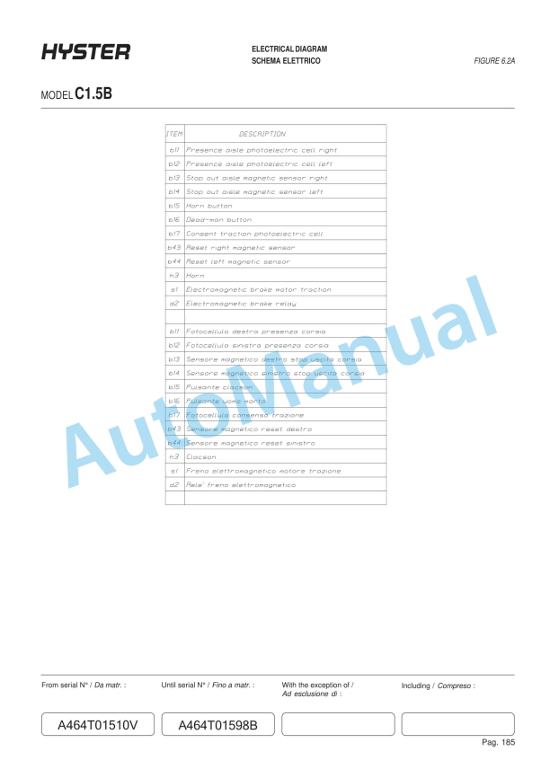
- 16.3. Electrical Schematic and System Description
- 16.3.1. Electrical Schematic
- 16.3.2. Schematic Location Number
- 16.3.3. Electrical Components
- 16.3.4. Electrical Wires
- 16.3.5. Electrical Connectors
- 16.3.6. Main Electrical Supply
- 16.3.7. Cab Fuse Panel
- 16.3.8. Electric Console
- 16.3.9. Flyback Diodes
- 16.3.10. CAN (Controller Area Network)
- 16.3.11. Information Display
- 16.3.12. General Fault Finding
- 16.4. Wire Harness Identification and Connector Location
- 16.4.1. Frame Harness
- 16.4.2. Harnesses Frame to E-Console
- 16.4.3. E-Console Harness
- 16.4.4. Cab Roof Harness
- 16.4.5. Cab Underfloor Harness
- 16.4.6. Cab Rear Harness
- 16.4.7. Armrest Harness
- 16.4.8. Engine Harness
- 16.4.9. XMSN Harness
- 16.4.10. Hydraulics Harness
- 16.4.11. Power Distribution Harness
- 16.4.12. Boom Valves Harness
- 16.4.13. Boom Lights Harness
- 16.4.14. Front Light Harness
- 16.4.15. LLMI and Display LLMI Harness
- 17. RM2055-(07-2019)-UK-EN
- 17.1. Series Code / Model Designation Reference Table
- 17.2. General
- 17.2.1. Serial Number Data
- 17.3. Truck Handling Procedures
- 17.3.1. Moving and Towing a Lift Truck
- 17.3.2. Putting a Lift Truck on Blocks
- 17.3.3. Cleaning a Lift Truck
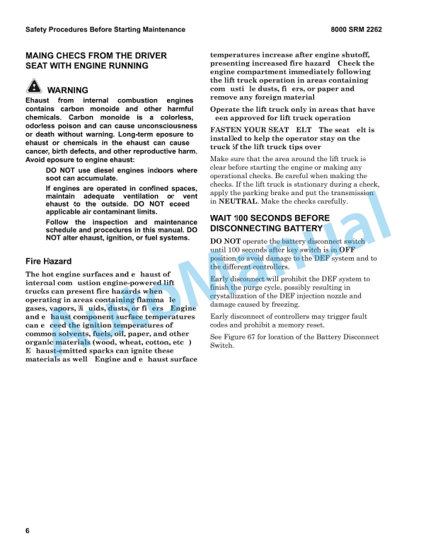
- 17.4. Safety Procedures Before Starting Maintenance
- 17.4.1. Making Checks with Engine Running
- 17.4.2. Wait 100 Seconds Before Disconnecting Battery
- 17.5. Periodic Maintenance Schedule
- 17.5.1. Daily Inspection
- 17.5.2. Initial Inspection
- 17.5.3. Periodic Maintenance
- 17.6. Container Attachment Periodic Maintenance Schedule
- 17.7. Periodic Maintenance Procedures
- 17.7.1. Air Conditioning System
- 17.7.2. Attachment Beams
- 17.7.3. Attachment Control System Signals
- 17.7.4. Attachment Pivot Pins
- 17.7.5. Automatic Greasing System (Optional)
- 17.7.6. Boom Bearing Pads
- 17.7.7. Brake Cooling Filter
- 17.7.8. Brake System Accumulator
- 17.7.9. Cab Air Filter
- 17.7.10. Cab Door Hinges
- 17.7.11. Cooling System
- 17.7.12. Drive Axle (AXLETECH)
- 17.7.13. Drive Axle (KESSLER)
- 17.7.14. Drive Shaft
- 17.7.15. Engine Air Filter
- 17.7.16. Engine Air Intake Piping and Charge Air Piping
- 17.7.17. Engine and Transmission Mounts
- 17.7.18. Engine Compartment
- 17.7.19. Engine Drive Belt, Tensioner and Pulleys
- 17.7.20. Engine Oil
- 17.7.21. Engine Valve Adjustment
- 17.7.22. Extension Cylinder Support Pads
- 17.7.23. Fault Condition
- 17.7.24. Frame, Boom and Attachment
- 17.7.25. Fuel, Oil, or Coolant Leaks
- 17.7.26. Fuel/Water Separator and Fuel Filter
- 17.7.27. Horn, Gauges, Lights, Alarms and Control System
- 17.7.28. Hydraulic System Oil
- 17.7.29. Hydraulic Tank Breather
- 17.7.30. Hydraulic Tank Return Filter
- 17.7.31. Inching Pedal Sensor Calibration
- 17.7.32. Joystick, Switches and Pedals
- 17.7.33. LLMI System
- 17.7.34. Operator Presence System
- 17.7.35. Operator Restraint System
- 17.7.36. Parking and Service Brakes
- 17.7.37. Pivot Point Lubrication
- 17.7.38. Power Pile Slope Cylinder Bearings
- 17.7.39. Radiator Assembly
- 17.7.40. Rotator
- 17.7.41. Spreader Sideshift
- 17.7.42. Steering Axle Grease Fittings
- 17.7.43. Steering System
- 17.7.44. Steer Wheel Hub Oil And Bearings
- 17.7.45. Transmission
- 17.7.46. Twist Locks
- 17.7.47. Warning and Safety Labels
- 17.7.48. Windows and Mirrors
- 17.7.49. Windshield Washer Fluid Level
Rate this product
You may also like

Hyster Service Manual PDF
Hyster 2.6L, 3.0L, 3.3L Yanmar Diesel Engines Maintenance And Repair
$30.00


%20Service%20Manual&url=https://automanual.net/doc/hyster-c098-e3-50-5-50xl-service-manual/&media=https://automanual.net/wp-content/uploads/2026/01/hyster-c098-e350-550xl-service-manual-1.jpg)
%20Service%20Manual&url=https://automanual.net/doc/hyster-c005-h60-90c-service-manual/&media=https://automanual.net/wp-content/uploads/2026/01/hyster-c005-h60-90c-service-manual-1.jpg)
%20Service%20Manual&url=https://automanual.net/doc/hyster-c001-h1-25-1-75xl-service-manual/&media=https://automanual.net/wp-content/uploads/2026/01/hyster-c001-h125-175xl-service-manual-1.jpg)
%20Service%20Manual&url=https://automanual.net/doc/hyster-b174-r30es-service-manual/&media=https://automanual.net/wp-content/uploads/2026/01/hyster-b174-r30es-service-manual-1.jpg)
%20Service%20Manual&url=https://automanual.net/doc/hyster-c004-s3-00-5-50e-service-manual/&media=https://automanual.net/wp-content/uploads/2026/01/hyster-c004-s300-550e-service-manual-1.jpg)
%20Service%20Manual&url=https://automanual.net/doc/hyster-b168-j2-00-3-00xl-service-manual/&media=https://automanual.net/wp-content/uploads/2026/01/hyster-b168-j200-300xl-service-manual-1.jpg)
%20Service%20Manual&url=https://automanual.net/doc/hyster-c098-e70-120xl-service-manual/&media=https://automanual.net/wp-content/uploads/2026/01/hyster-c098-e70-120xl-service-manual-1.jpg)