 Service Manual 1")
 Service Manual 2")
 Service Manual 3")
 Service Manual 4")
 Service Manual 5")
Hyster K177 (H45-50-55-60-65XM) Service Manual
$30.00
- Type Of Manual: Service Manual
- Number of Pages: 696
- Size: 29.6MB
- Format: PDF
Category: Hyster Service Manual PDF
-
Model List:
- K177 (H45-50-55-60-65XM)
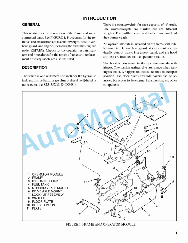
- 1. INTRODUCTION
- 2. GENERAL
- 3. DESCRIPTION
- 4. REMOVAL AND INSTALLATION OF THE ENGINE
- 5. CYLINDER HEAD AND MECHANISM
- 6. Cylinder Head, Removal
- 7. Cylinder Head, Disassembly
- 8. Cleaning And Inspection
- 9. Valve And Valve Seats
- 10. Studs For The Rocker Arms
- 11. Hydraulic Valve Lifters, Replacement
- 12. Hydraulic Valve Lifters, Cleaning And Inspection
- 13. Cylinder Head, Assembly
- 14. Cylinder Head, Installation
- 15. Rocker Arm Cover, Installation
- 16. TIMING GEAR COVER
- 17. Removal
- 18. Installation
- 19. CAMSHAFT
- 20. Removal
- 21. Inspection
- 22. Camshaft Bearings, Removal
- 23. Camshaft Bearings, Installation
- 24. DISTRIBUTOR
- 25. Removal
- 26. Installation
- 27. LUBRICATION SYSTEM
- 28. Oil Sump, Removal
- 29. Oil Sump, Installation
- 30. Oil Pump, Removal
- 31. Oil Pump, Disassembly and Repair
- 32. Oil Pump, Assembly
- 33. Oil Pump, Installation
- 34. PISTON AND CONNECTING ROD ASSEMBLIES
- 35. Connecting Rod Bearings, Replacement
- 36. Piston And Connecting Rod Assemblies, Removal
- 37. Disassembly
- 38. Piston, Cleaning And Inspection
- 39. Cylinder Bores, Inspection And Repair
- 40. Piston Rings
- 41. Assembly
- 42. Piston And Connecting Rod Assemblies, Installation
- 43. CRANKSHAFT
- 44. Main Bearings, Replacement
- 45. Oil Seal For The Rear Main Bearing, Replacement (GM 4-181 and 3.0L Only)
- 46. Oil Seal For The Rear Main Bearing, Replacement (Engines That Have A Two-Piece Oil Seal)
- 47. Crankshaft, Removal
- 48. Inspection and Repair
- 49. How To Check The Clearance Between The Main Bearings And Their Journals
- 50. Installation
- 51. FLYWHEEL AND FLYWHEEL HOUSING
- 52. Flywheel, Removal
- 53. Ring Gear, Replacement
- 54. Flywheel, Installation
- 55. COOLING SYSTEM
- 56. Coolant Pump
- 57. Fan Drive
- 58. Viscous Fan Drive
- 59. ENGINE SPECIFICATIONS
- 60. ENGINE DATA
- 61. CYLINDER HEAD
- 62. HYDRAULIC VALVE LIFTER
- 63. CAMSHAFT
- 64. PISTONS
- 65. CYLINDER BORE
- 66. CRANKSHAFT
- 67. CONNECTING RODS
- 68. COOLING SYSTEM
- 69. LUBRICATION SYSTEM
- 70. TORQUE SPECIFICATIONS
- 71. INTRODUCTION
- 72. GENERAL
- 73. DESCRIPTION
- 74. REPAIRS
- 75. OPERATOR MODULE
- 76. Removal
- 77. Installation
- 78. HOOD AND SIDE COVERS
- 79. Removal
- 80. Installation
- 81. OVERHEAD GUARD
- 82. Removal and Installation
- 83. COUNTERWEIGHT
- 84. Removal
- 85. Installation
- 86. EXHAUST SYSTEM
- 87. Replacing the Muffler
- 88. RADIATOR AND COOLING SYSTEM
- 89. Removal
- 90. Installation
- 91. OPERATOR RESTRAINT SYSTEM
- 92. Removal, Engine ONLY
- 93. Removal, Engine and Transmission
- 94. Installation, Engine ONLY
- 95. Installation, Engine and Transmission
- 96. FUEL AND HYDRAULIC TANKS
- 97. Inspection
- 98. Repairs, Small Leaks
- 99. Repairs, Large Leaks
- 100. Cleaning, Steam Method
- 101. Cleaning, Chemical Solution Method
- 102. Additional Preparations for Repairs
- 103. SAFETY LABELS
- 104. INTRODUCTION
- 105. GENERAL
- 106. DESCRIPTION AND OPERATION
- 107. Fuel Tank
- 108. Fuel Filter and Fuel Valve Unit
- 109. Vaporizer
- 110. Carburetor
- 111. Solenoid Valve
- 112. Idle Control Actuator
- 113. Governor System
- 114. REPAIRS
- 115. REPLACEMENT OF THE HOSES
- 116. LPG TANK
- 117. Removal
- 118. Installation
- 119. HYDROSTATIC RELIEF VALVE
- 120. Removal and Installation
- 121. FILTER UNIT
- 122. Replacement Of The Fuel Filter Element
- 123. Replacement of the Diaphragm and Fuel Valve
- 124. VAPORIZER
- 125. Removal
- 126. Disassembly
- 127. Cleaning
- 128. Inspection
- 129. Assembly
- 130. Installation
- 131. CARBURETOR
- 132. Removal
- 133. Disassembly
- 134. Cleaning
- 135. Assembly
- 136. Installation
- 137. SOLENOID VALVE
- 138. CHECKS AND ADJUSTMENTS
- 139. GOVERNOR SYSTEM
- 140. CHECK THE FILTER UNIT
- 141. CHECK THE VAPORIZER
- 142. Pressure Reducer Valve
- 143. Vapor Valve
- 144. ADJUST THE CARBURETOR
- 145. Idle Adjustments
- 146. Power Mixture
- 147. ADJUST THE THROTTLE LINKAGE
- 148. Check The Monotrol Pedal
- 149. TROUBLESHOOTING
- 150. LPG Fuel System
- 151. Safety Precautions Maintenance and Repair
- 152. General
- 153. Description and Operation
- 154. Fuel Tank
- 155. Oxygen Sensor
- 156. Regulator
- 157. Start Mode
- 158. Idle Mode
- 159. Run Mode
- 160. Resonator
- 161. Carburetor
- 162. Start Mode
- 163. Idle Mode
- 164. Run Mode
- 165. Governor
- 166. Hoses Replacement
- 167. LPG Tank Repair
- 168. Install
- 169. Relief Valve Repair
- 170. Remove and Install
- 171. Carburetor Repair
- 172. Disassemble
- 173. Assemble
- 174. Install
- 175. Fuel Injector Repair
- 176. Clean and Inspect
- 177. Install
- 178. Governor Repair
- 179. Inspect
- 180. Install
- 181. Regulator Repair
- 182. Install
- 183. Oxygen Sensor Repair
- 184. Remove and Install
- 185. Vacuum Switches Repair
- 186. Remove and Install
- 187. Inspect
- 188. Resistor Repair
- 189. Remove and Install
- 190. Inspect
- 191. Carburetor and New Regulator Adjustment
- 192. Idle Speed and Fuel Mixture
- 193. Idle Control Adjustment
- 194. Governor Checks and Adjustments
- 195. Adjustments
- 196. Throttle Linkage Adjustment
- 197. MONOTROL Pedal Check
- 198. Check Engine Light
- 199. Inspect Warning Lamp
- 200. Check Feedback Operation
- 201. Check VAC1 and VAC2 Signals
- 202. Check Resistor
- 203. Check Fuel Injector
- 204. Check Oxygen Sensor
- 205. Check Vacuum Switch 1
- 206. Check Vacuum Switch 2
- 207. After Completing Checks
- 208. Troubleshooting
- 209. Table 1. Adjusting Screw
- 210.
- 210.1. Single-Speed Powershift Transmission
- 210.2. Safety Precautions Maintenance and Repair
- 210.3. General
- 210.4. Description and Operation
- 210.5. General
- 210.6. Torque Converter
- 210.7. Description
- 210.8. Operation
- 210.9. Clutch Assemblies
- 210.10. Description
- 210.11. Operation
- 210.12. Hydraulic System
- 210.13. General
- 210.14. Control Valve
- 210.15. General
- 210.16. Clutch Pressure Regulator
- 210.17. Inching Spool Assembly
- 210.18. Direction Spool
- 210.19. Modulator Circuit
- 210.20. Torque Converter Regulator
- 210.21. MONOTROL Pedal
- 210.22. MONOTROL Pedal Start Circuit
- 210.23. Direction Control Lever
- 210.24. Differential
- 210.25. Oil Flow Diagrams
- 210.26. Neutral
- 210.27. Modulator Operation
- 210.28. Forward
- 210.29. Forward-Inching
- 211.
- 212.
- 212.1. INTRODUCTION
- 212.2. REPAIRS
- 212.3. TROUBLESHOOTING
- 212.4. TORQUE SPECIFICATIONS
- 213.
- 213.1. INTRODUCTION
- 213.2. REPAIRS
- 213.3. TORQUE SPECIFICATIONS
- 213.4. TROUBLESHOOTING
- 214.
- 214.1. INTRODUCTION
- 214.2. REPAIRS
- 214.3. CHECKS AND ADJUSTMENTS
- 214.4. TROUBLESHOOTING
- 215.
- 216.
- 216.1. INTRODUCTION
- 216.2. CHECKS AND ADJUSTMENTS
- 216.3. TROUBLESHOOTING
- 217.
- 217.1. INTRODUCTION
- 217.2. REPAIRS
- 217.3. CHECKS AND ADJUSTMENTS
- 217.4. TROUBLESHOOTING
- 218.
- 219.
- 220.
- 221.
- 221.1. INTRODUCTION
- 221.2. REPAIRS
- 222.
- 223.
- 223.1. INTRODUCTION
- 223.2. REPAIRS
- 223.3. CHECKS AND ADJUSTMENTS
- 223.4. TROUBLESHOOTING
- 224.
- 225.
- 226.
- 226.1. INTRODUCTION
- 227.
- 227.1. INTRODUCTION
- 227.2. SAFETY PROCEDURES WHEN WORKING NEAR THE MAST
- 227.3. REPAIRS
- 227.4. CHECKS AND ADJUSTMENTS
- 227.5. TROUBLESHOOTING
- 228.
- 229.
- 229.1. Periodic Maintenance
- 229.2. Safety Precautions Maintenance and Repair
- 229.3. General
- 229.4. Serial Number
- 229.5. How to Move Disabled Lift Truck
- 229.6. How to Tow Lift Truck
- 229.7. How to Put Lift Truck on Blocks
- 229.8. How to Raise Drive Tires
- 229.9. How to Raise Steering Tires
- 229.10. Maintenance Schedule
- 229.11. Maintenance Procedures Every 8 Hours or Daily
- 229.12. How to Make Checks with Engine Stopped
- 229.13. Tires and Wheels
- 229.14. Forks, Mast, and Lift Chains, Inspect
- 229.15. Safety Labels
- 229.16. Operator Restraint System
- 229.17. Steering Column Latch
- 229.18. Fuel, Oil, or Coolant Leaks, Check
- 229.19. Drive Belt
- 229.20. Powershift Transmission Oil Temperature
- 229.21. Powershift Transmission Oil Level
- 229.22. Hydrostatic Transmission Oil Level
- 229.23. Engine Oil
- 229.24. Hydraulic System
- 229.25. Air Filter
- 229.26. How to Make Checks With Engine Running
- 229.27. Gauges, Indicator Lights, Horn, Fuses, and Relays
- 229.28. Check Engine Light (Mazda and GM LPG Closed Loop with Low-Emissi
- 229.29. Malfunction Indicator Lamp (GM 3.0L Gasoline Engine)
- 229.30. Engine Oil Pressure
- 229.31. Cooling System
- 229.32. Steering System
- 229.33. Service Brakes
- 229.34. Parking Brake
- 229.35. Water Separator, Diesel Engine
- 229.36. Fuel Filter, Diesel Engine
- 229.37. Diesel Fuel System, Remove Air
- 229.38. Control Levers and Pedals
- 229.39. Lift System, Operate
- 229.40. Cooling System
- 229.41. Maintenance Procedures Every 250 Hours or 6 Weeks
- 229.42. Air Filter
- 229.43. Drive Belt
- 229.44. Mazda M4-2.0G and M4-2.2G Engines
- 229.45. GM 3.0L
- 229.46. Perkins 704-26 (UB)
- 229.47. Engine Oil and Filter
- 229.48. Brake Fluid
- 229.49. Hydraulic Tank Breather
- 229.50. Battery
- 229.51. Lift Chains
- 229.52. Lubrication
- 229.53. Wear, Check
- 229.54. Steering Axle
- 229.55. Fuel System
- 229.56. Engine Speed, Diesel, Perkins 704-26 (UB)
- 229.57. Engine Speed, LPG Carburetor, Mazda and GM (Aisan Open-Loop and
- 229.58. Engine Speed, LPG Carburetor, Mazda (Impco)
- 229.59. Engine Speed, LPG Carburetor, GM 3.0L (Impco)
- 229.60. Engine Speed, Mazda Gasoline Carburetor
- 229.61. Hydraulic System
- 229.62. Maintenance Procedures Every 500 Hours or 3 Months
- 229.63. Drain Tar From Aisan LPG Regulator
- 229.64. Maintenance Procedures Every 1000 Hours or 6 Months
- 229.65. Diesel Fuel System
- 229.66. Fuel Filter, Replace
- 229.67. Water Separator, Remove Water
- 229.68. Water Separator, Replace
- 229.69. Diesel Fuel System Air Removal
- 229.70. Differential and Drive Axle, Powershift Transmission
- 229.71. Drive Axle, Hydrostatic Transmission
- 229.72. Valve Clearance, Check and Adjust
- 229.73. Ignition System
- 229.74. GM 3.0L LPG (IMPCO)
- 229.75. GM 3.0L LPG (Aisan)
- 229.76. Mazda M4-2.0G and M4-2.2G
- 229.77. Aisan Regulator Pressure/Diaphragm and O-Ring Checks
- 229.78. PCV Valve
- 229.79. Integral Sideshift Carriage, Check Bearings
- 229.80. Control Levers and Pedals
- 229.81. Maintenance Procedures Every 2000 Hours or Yearly
- 229.82. Hydraulic System
- 229.83. Hydraulic Oil and Filter, Replace
- 229.84. Powershift Transmission Oil and Filter
- 229.85. Replace
- 229.86. Hydrostatic Transmission Oil and Filter
- 229.87. Replace
- 229.88. Cooling System
- 229.89. Service Brakes
- 229.90. Differential
- 229.91. Transmission Axle Shaft Oil (Hydrostatic Transmission)
- 229.92. Gasoline Fuel Filter
- 229.93. PCV Valve
- 229.94. LPG Filter
- 229.95. Fuel Filter (Aisan LPG System), Replace
- 229.96. LPG Fuel Injector (Aisan Closed-Loop Low Emission System)
- 229.97. Integral Sideshift Carriage, Replace Bearings
- 229.98. Safety Procedures When Working Near Mast
- 229.99. Hood Latch Check
- 229.100. Lift Chain Adjustments
- 229.101. Lift and Tilt System Leak Check
- 229.102. Lift Cylinder, Leak Check
- 229.103. Tilt Cylinder, Leak Check
- 229.104. Charging Battery
- 229.105. Diesel Engine Fuel Injector Check
- 229.106. Welding Repairs
- 229.107. Overhead Guard Changes
- 229.108. Wheel and Tire Replacement
- 229.109. Solid Rubber Tire, Change S40-65XM Models
- 229.110. Remove and Install Tire on Wheel
- 229.111. Pneumatic Tire, Repair H45-65XM Models
- 229.112. Remove Wheels From Lift Truck
- 229.113. Remove Wheel From Tire
- 229.114. Install Wheel on Tire
- 229.115. Add Air to Pneumatic Tires
- 229.116. Wheels, Install
- 229.117. Dual Drive Wheels, Install
- 229.118. Solid Rubber Tire, Change H45-65XM Models
- 229.119. Remove Wheel From Tire
- 229.120. Install Wheel in Tire
- 229.121. Adhesives and Sealants
- 229.122. Table 1. Maintenance Schedule
- 230.
- 230.1. LIFT TRUCK WEIGHTS
- 230.2. TIRE PRESSURE
- 230.3. CAPACITIES
- 230.4. ELECTRICAL SYSTEM – GASOLINE/LPG
- 230.5. ELECTRICAL SYSTEM – DIESEL
- 230.6. TRANSMISSION OIL PRESSURES
- 230.7. HYDRAULIC SYSTEM
- 230.8. STALL SPEEDS H2.00-3.20XM (H45-65XM)
- 230.9. STALL SPEEDS S2.00-3.20XM (S40-65XM)
- 230.10. ENGINE SPECIFICATIONS – GASOLINE/LPG
Rate this product
You may also like

Hyster Service Manual PDF
$30.00

Hyster Service Manual PDF
$30.00
%20Service%20Manual&url=https://automanual.net/doc/hyster-k177-h45-50-55-60-65xm-service-manual/&media=https://automanual.net/wp-content/uploads/2026/01/hyster-k177-h45-50-55-60-65xm-service-manual-1.jpg)
%20Service%20Manual&url=https://automanual.net/doc/hyster-b460-k1-0m-k1-0h-k1-0h-wp-service-manual/&media=https://automanual.net/wp-content/uploads/2026/01/hyster-b460-k10m-k10h-k10h-wp-service-manual-1.jpg)
%20Maintenance%20Schedule&url=https://automanual.net/doc/hyster-c098-e3-50-5-50xl-e4-50xls-maintenance-schedule/&media=https://automanual.net/wp-content/uploads/2026/01/hyster-c098-e350-550xl-e450xls-maintenance-schedule-1.jpg)
%20Service%20Manual&url=https://automanual.net/doc/hyster-b168-j40-60xl-service-manual/&media=https://automanual.net/wp-content/uploads/2026/01/hyster-b168-j40-60xl-service-manual-1.jpg)
%20Service%20Manual&url=https://automanual.net/doc/hyster-b210-n30ah-service-manual/&media=https://automanual.net/wp-content/uploads/2026/01/hyster-b210-n30ah-service-manual-1.jpg)
%20Service%20Manual&url=https://automanual.net/doc/hyster-c010-s1-50-2-00xms-service-manual/&media=https://automanual.net/wp-content/uploads/2026/01/hyster-c010-s150-200xms-service-manual-1.jpg)