


Hyster S3.50-5.50XL to E4.50XLS Steering Axle Maintenance And Repair
$30.00
- Type Of Manual: Maintenance And Repair
- Number of Pages: 1806
- Size: 88.1MB
- Format: PDF
Category: Hyster Service Manual PDF
-
Model List:
- S3.50-5.50XL, S3.50-5.50XM, E3.50-5.50XL, H3.50-5.00XL, H6.00-7.00XL, H8.00-16.00XL, H8.00-12.00XM, H13.00-14.00XM, H16.00XM-6, H10.00-12.00XM-12EC, E3.50-5.50XL, E4.50XLS
- 1. RM0326-(03-2007)-US-EN
- 1.1. General
- 1.2. Description
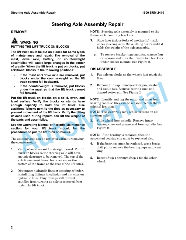
- 1.3. Steering Axle Assembly Repair
- 1.4. Wheels and Hubs Repair (All Units)
- 1.5. Spindles and Bearings Repair (All Units)
- 1.6. Tie Rods Repair (All Units)
- 1.7. Steering Cylinder Repair
- 1.8. Troubleshooting
- 2. RM0626-(11-2001)-US-EN
- 2.1. Cooling System
- 2.2. Safety Precautions Maintenance and Repair
- 2.3. General
- 2.4. Description
- 2.5. Radiator
- 2.6. Radiator Cap
- 2.7. Thermostat
- 2.8. Water Pump
- 2.9. Fan and Fan Shroud
- 2.10. Cooling System Checks
- 2.11. Radiator
- 2.12. Thermostat
- 2.13. Water Pump
- 2.14. Exhaust Leaks
- 2.15. Fan and Fan Shroud
- 2.16. Radiator Cleaning
- 2.17. Troubleshooting
- 3. RM0002-(01-2016)-US-EN
- 3.1. General
- 3.2. Description
- 3.3. Alternator Repair
- 3.4. General Check and Adjustment
- 3.5. Low Output Check (Type A or Type B)
- 3.6. High Output Check (Type A or Type B)
- 3.7. Brushes Circuit Check
- 3.8. Diodes Check
- 3.9. Diode Bridge Check
- 3.10. Rotor Field Winding Check
- 3.11. Stator Windings Check
- 3.12. Voltage Regulator Check
- 3.13. Troubleshooting
- 4. RM0046-(11-2014)-US-EN
- 5. RM0103-(03-2007)-US-EN
- 5.1. Tilt Cylinders
- 5.2. Safety Precautions Maintenance and Repair
- 5.3. General
- 5.4. Description
- 5.5. Tilt Cylinder Repair
- 5.6. Disassemble
- 5.7. Assemble
- 5.8. Tilt Cylinders With O-Ring or Single-Lip Seals
- 5.9. Tilt Cylinders for XM and XMS Models
- 5.10. Tilt Cylinders for XL, XLS, and XL 3 Models
- 5.11. Tilt Cylinders for H700-800A and Early Model H700-920B
- 5.12. Install
- 5.13. Tilt Cylinders Using Chevron Packing
- 5.14. Tilt Cylinder Leak Check
- 5.15. Tilt Cylinder Stroke and Mast Tilt Angle Adjustment
- 5.16. Torque Specifications
- 5.17. Piston Rod Nut
- 5.18. Retainer
- 5.19. Troubleshooting
- 5.20. Table 1. Movement Rates (Maximum) for Tilt Cylinders
- 6. RM0106-(01-2016)-US-EN
- 6.1. General
- 6.2. Description and Operation
- 6.3. Starter Repair
- 6.4. General Checks and Adjustments
- 6.5. Troubleshooting
- 7. RM0231-(01-2016)-US-EN
- 7.1. General
- 8. RM0927-(11-2015)-US-EN
- 8.1. General
- 8.2. Description
- 8.3. Counterweight Repair
- 8.4. Hood and Air Cleaner Repair
- 8.5. Hydraulic Tank Repair
- 8.6. Fuel Tank Repair
- 8.7. Cooling System and Radiator Repair
- 8.8. Cab Repair
- 8.9. Engine and Transmission Repair
- 8.10. Label Replacement
- 9. RM0936-(03-2007)-US-EN
- 9.1. Steering System
- 9.2. Safety Precautions Maintenance and Repair
- 9.3. General
- 9.4. Description
- 9.5. Steering Wheel and Column Assembly
- 9.6. General
- 9.7. Steering Wheel and Horn
- 9.8. Install
- 9.9. Steering Control Unit Repair
- 9.10. General
- 9.11. Description
- 9.12. Operation
- 9.13. Disassemble
- 9.14. Assemble and Install
- 9.15. Steering System Air Removal
- 9.16. Steering Relief Pressure Check
- 9.17. Troubleshooting
- 10. RM0937-(04-2010)-US-EN
- 10.1. Dry Brake System
- 10.2. Safety Precautions Maintenance and Repair
- 10.3. General
- 10.4. Description
- 10.5. Operation
- 10.6. Service Brakes
- 10.7. Parking Brake
- 10.8. Air Tank Repair
- 10.9. Relief Valve
- 10.10. Drain Valve
- 10.11. Brake Pedal Valve Repair
- 10.12. Disassemble, Inspect, and Assemble
- 10.13. Install
- 10.14. Air Chambers Repair
- 10.15. Disassemble
- 10.16. Inspect
- 10.17. Assemble
- 10.18. Install
- 10.19. Actuator Arms Repair
- 10.20. Inspect
- 10.21. Install
- 10.22. Brake Assemblies Repair
- 10.23. Brake Shoe, Remove
- 10.24. Camshaft, Remove
- 10.25. Inspect
- 10.26. Camshaft, Install
- 10.27. Brake Shoe, Install
- 10.28. Air Dryer
- 10.29. Description
- 10.30. Cartridge
- 10.31. Install
- 10.32. Install
- 10.33. Quick-Release Valve
- 10.34. Governor Check and Adjustment for Air Compressor
- 10.35. Brake Shoes Adjustment
- 10.36. Specifications
- 10.37. Troubleshooting
- 10.38. Service Brakes
- 10.39. Service Brakes, Park Function
- 10.40. Table 1. Air Chambers Operation
- 11. RM0938-(03-2007)-US-EN
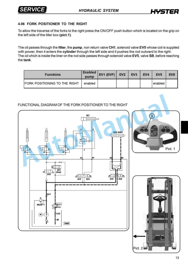
- 11.1. Hydraulic System
- 11.2. Safety Precautions Maintenance and Repair
- 11.3. General
- 11.4. Description and Operation
- 11.5. Hydraulic Tank
- 11.6. Hydraulic Pump
- 11.7. Steering Priority Flow Valve
- 11.8. Pilot Valve
- 11.9. Main Control Valve
- 11.10. Unloader Valve
- 11.11. Hydraulic Operation
- 11.12. Checks and Adjustments
- 11.13. Quick Disconnect Fittings
- 11.14. Steering Priority Flow Valve
- 11.15. Steering Relief Pressure
- 11.16. Modulator Valve
- 11.17. Pilot Valve and Pressure Reducing Valve
- 11.18. Accumulator
- 11.19. Main Control Valve
- 11.20. Relief Pressure Check
- 11.21. Check Valves
- 11.22. Unloader Valve
- 11.23. Hydraulic Pump Repair
- 11.24. Disassemble
- 11.25. Clean and Inspect
- 11.26. Assemble
- 11.27. Install
- 11.28. Pilot Accumulator Replacement
- 11.29. Install
- 11.30. Pilot Valve Repair
- 11.31. Disassemble
- 11.32. Clean and Inspect
- 11.33. Assemble
- 11.34. Install
- 11.35. Control Levers and Joystick Repair
- 11.36. Install
- 11.37. Calibration and Diagnostics
- 11.38. General
- 11.39. Description
- 11.40. Lever and Joystick Calibration
- 11.41. Flow Adjustment
- 11.42. Dead Band Value Setting
- 11.43. Lowering Delay
- 11.44. PWM and I/O Module Readouts
- 11.45. Function Disable
- 11.46. General Startup
- 11.47. Minimum system requirements
- 11.48. Install the Hydraulic Controls Program
- 11.49. DelayTimeFile (Reset)
- 11.50. Select the Processor Speed
- 11.51. Hydraulic Controls Program
- 11.52. Calibration
- 11.53. Joystick/Lever Calibration
- 11.54. Valve Flow Adjustment
- 11.55. Diagnostics
- 11.56. Calibration System Shutdown
- 11.57. LED Diagnostics
- 11.58. Electrical Connections
- 11.59. Specifications
- 11.60. Table 1. Main Control Valve Port Settings
- 11.61. Table 2. Processor Speed Settings
- 11.62. Table 3. PWM Board LED Error Codes
- 11.63. Table 4. Altering PT FLT I/O Board LEDs (Old Logic)
- 11.64. Table 5. Altering PT FLT I/O Board LEDs (New Logic)
- 11.65. Table 6. Fixed PT Logic I/O Boards LEDs
- 11.66. Table 7. ECH
- 11.67. Table 8. PWM Driver Module
- 11.68. Table 9. Input/Output Module 1
- 11.69. Table 10. Input/Output Module 2
- 11.70. Table 11. Altering PT FLT
- 11.71. Table 12. Fixed PT FLT
- 11.72. Table 13. ECH
- 12. RM0940-(07-2013)-US-EN
- 12.1. Capacities and Specifications
- 12.2. Safety Precautions Maintenance and Repair
- 12.3. Lift Truck Weights
- 12.4. Capacities
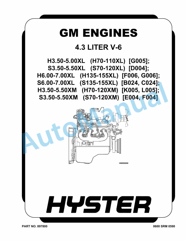
- 12.5. Engine Specifications
- 12.6. Perkins Diesel
- 12.7. Cummins Diesel/LPG
- 12.8. Hydraulic System
- 12.9. Electrical System
- 12.10. Tire Sizes
- 12.11. Mast Speeds
- 12.12. Perkins Diesel
- 12.13. Cummins Diesel/LPG
- 12.14. Torque Specifications, Cummins Diesel
- 12.15. Lubrication System
- 12.16. Torque Specifications, Perkins Diesel
- 12.17. Cylinder Head Assembly
- 12.18. Piston and Connecting Rod Assemblies
- 12.19. Crankshaft Assembly
- 12.20. Timing Case and Drive Assembly
- 12.21. Turbocharger
- 12.22. Lubrication System
- 12.23. Fuel System
- 12.24. Cooling System
- 12.25. Flywheel and Housing
- 12.26. Aspiration System
- 12.27. Electrical Equipment
- 12.28. Auxiliary Equipment
- 12.29. Torque Specifications – Perkins, Tier 2
- 12.30. Cylinder Head Assembly
- 12.31. Piston and Connecting Rod Assemblies
- 12.32. Crankshaft Assembly
- 12.33. Timing Case and Drive Assembly
- 12.34. Turbocharger
- 12.35. Lubrication System
- 12.36. Fuel System
- 12.37. Cooling System
- 12.38. Flywheel
- 12.39. Auxiliary Equipment
- 12.40. Torque Specifications, General
- 12.41. Transmission
- 12.42. Driveline and Axle
- 12.43. Differential
- 12.44. Brakes – Wet
- 12.45. Brakes – Dry
- 12.46. Steering
- 12.47. Hydraulic System
- 12.48. Carriage
- 12.49. Tilt Cylinders
- 12.50. Wiper Arms, Front
- 12.51. Hyster T-50 Transmission Pressures (Powershift and Automatic)
- 12.52. TE-10 Transmission Specifications
- 12.53. Electrical
- 12.54. Hydraulic Cooler Lines
- 12.55. Torque Specifications for Lubricated or Plated Screw Threads
- 12.56. Table 1. Temperature Sensor (In Speed Sensor) Resistance vs Temp
- 12.57. Table 2. Grade 5
- 12.58. Table 3. Grade 8
- 12.59. Table 4. Grades 8.8, 10.9, and 12.9
- 12.60. Table 5. O-ring Port Plug Torque Chart
- 12.61. Table 6. Pipe Plug Torque Chart
- 13. RM0944-(08-2012)-US-EN
- 13.1. Planetary Drive Axle
- 13.2. Safety Precautions Maintenance and Repair
- 13.3. General
- 13.4. Description
- 13.5. Operation
- 13.6. Identification
- 13.7. Removal
- 13.8. Disassembly
- 13.9. Planetary Spider and Gearing Assembly H8.00-12.00XM (H170-280HD)
- 13.10. Planetary Spider and Gearing Assembly H13.00-14.00XM (H300-330HD
- 13.11. Wheel End
- 13.12. Spindle and Piston Housing
- 13.13. Cleaning
- 13.14. Clean Ground or Polished Parts
- 13.15. Clean Parts With Rough Finish
- 13.16. Clean Axle Assemblies
- 13.17. Drying Cleaned Parts
- 13.18. Corrosion Prevention
- 13.19. Parts Inspection
- 13.20. Tapered Roller Bearings
- 13.21. Bevel Pinion and Ring Gear Sets
- 13.22. Main Differential Assembly
- 13.23. Axle Shafts
- 13.24. Repair or Replace Parts
- 13.25. Repair Welding
- 13.26. Apply Silicone Gasket Material
- 13.27. Assembly
- 13.28. Spindle and Piston Housing to Axle Housing
- 13.29. Wet Disc Brakes
- 13.30. Adjust Wheel Bearing Preload
- 13.31. Planetary Spider and Gearing Assembly H8.00-12.00XM (H170-280HD)
- 13.32. Planetary Spider and Gearing Assembly H13.00-14.00XM (H300-330HD
- 13.33. Planetary Spider Assembly
- 13.34. Installation
- 13.35. Fill Wet Disc Brakes With Hydraulic Fluid
- 13.36. Torque Specifications
- 13.37. Lubrication Specification
- 14. RM0943-(03-2007)-US-EN
- 14.1. Main Control Valve
- 14.2. Safety Precautions Maintenance and Repair
- 14.3. General
- 14.4. Description
- 14.5. Operation
- 14.6. Lift Section
- 14.7. Tilt/Auxiliary Section
- 14.8. Relief Valves
- 14.9. Unloader Valve
- 14.10. Main Control Valve Repair
- 14.11. Disassemble
- 14.12. Auxiliary Side
- 14.13. Lift Side
- 14.14. Clean and Inspect
- 14.15. Assemble
- 14.16. Auxiliary Side
- 14.17. Lift Side
- 14.18. Install
- 14.19. Pressure Relief Valve Check and Adjustment
- 14.20. Check and Adjust
- 14.21. Replace
- 14.22. Specifications
- 14.23. Troubleshooting
- 15. RM0945-(08-2011)-US-EN
- 15.1. Planetary Drive Axle
- 15.2. Safety Precautions Maintenance and Repair
- 15.3. General
- 15.4. Description
- 15.5. Operation
- 15.6. Identification
- 15.7. Removal
- 15.8. Disassembly
- 15.9. Brake Drum
- 15.10. Planetary Spider and Gearing Assembly H8.00-12.00XM (H170-280HD)
- 15.11. Dry Brakes
- 15.12. Planetary Spider and Gearing Assembly H13.00-14.00XM (H300-330HD
- 15.13. Spindle and Brake Spider
- 15.14. Cleaning
- 15.15. Ground or Polished Parts
- 15.16. Parts With Rough Finish
- 15.17. Axle Assemblies
- 15.18. Drying Cleaned Parts
- 15.19. Corrosion Prevention
- 15.20. Parts Inspection
- 15.21. Tapered Roller Bearings
- 15.22. Bevel Pinion and Ring Gear Sets
- 15.23. Main Differential Assembly
- 15.24. Axle Shafts
- 15.25. Repair or Replace Parts
- 15.26. Repair Welding
- 15.27. Apply Silicone Gasket Material
- 15.28. Assembly
- 15.29. Spindle, Brake Spider, and Brake
- 15.30. Wheel End
- 15.31. Adjust Wheel Bearing Preload
- 15.32. Planetary Spider and Gearing Assembly H8.00-12.00XM (H170-280HD)
- 15.33. Planetary Spider and Gearing Assembly H13.00-14.00XM (H300-330HD
- 15.34. Planetary Spider Assembly
- 15.35. Installation
- 15.36. Torque Specifications
- 15.37. Lubrication Specification
- 16. RM0951-(08-2014)-US-EN
- 17. RM0969-(02-2016)-US-EN
- 17.1. General
- 17.2. Description
- 17.3. Operation
- 17.4. Carriage and Attachment Repair
- 17.5. Attachment Without Carriage Repair
- 17.6. Sideshift Cylinders Repair
- 17.7. Extension Cylinders Repair
- 17.8. Vertical End Beams Repair
- 17.9. Twist Locks Repair for Model 553
- 17.10. Hooks Replacement for Model 555
- 17.11. Twist Locks Repair for Model 558
- 17.12. Bleed the System
- 17.13. Valve Assembly
- 17.14. Slide Pad Replacement
- 17.15. Adjustments
- 17.16. Maintenance
- 17.17. Troubleshooting
- 18. RM1068-(05-2004)-US-EN
- 18.1. Perkins Tier 2 Diesel Engines
- 18.2. Safety Precautions Maintenance and Repair
- 18.3. General
- 18.4. General Safety Rules
- 18.5. Description
- 18.6. Engine Serial Number Codes
- 18.7. Engine Data
- 18.8. Engine Removal and Installation
- 18.9. Cylinder Head Assembly Repair
Rate this product
You may also like
Hyster Service Manual PDF
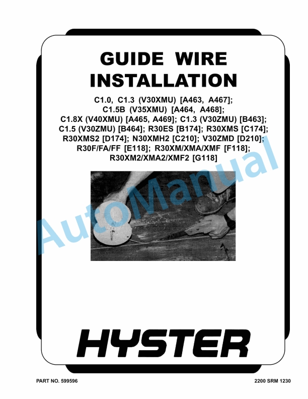
Hyster C1.0 to R30XMF2 Guide Wire Installation Maintenance And Repair
$30.00
Hyster Service Manual PDF
$30.00

Hyster Service Manual PDF
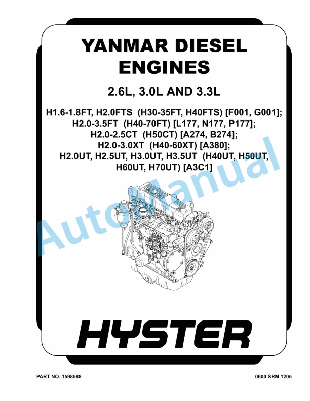
Hyster 2.6L, 3.0L, 3.3L Yanmar Diesel Engines Maintenance And Repair
$30.00
%20Service%20Manual&url=https://automanual.net/doc/hyster-b447-s1-0c-s1-2c-s1-5c-service-manual/&media=https://automanual.net/wp-content/uploads/2026/01/hyster-b447-s10c-s12c-s15c-service-manual-1.jpg)
%20Service%20Manual&url=https://automanual.net/doc/hyster-a406-r1-4-r1-6-service-manual/&media=https://automanual.net/wp-content/uploads/2026/01/hyster-a406-r14-r16-service-manual-1.jpg)
%20Service%20Manual&url=https://automanual.net/doc/hyster-b418-p1-6-p1-8-p2-0-p2-2-service-manual/&media=https://automanual.net/wp-content/uploads/2026/01/hyster-b418-p16-p18-p20-p22-service-manual-1.jpg)