


Komatsu Operation and Maintenance Manual PDF
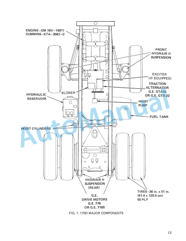
Komatsu 170D Dump Truck Operation and Maintenance Manual DG534
Komatsu Operation and Maintenance Manual PDF
Komatsu 730E Dump Truck Operation and Maintenance Manual CEAM011200
Komatsu Operation and Maintenance Manual PDF
Komatsu 730E Dump Truck Field Assembly Instruction CEAW004103
Komatsu Operation and Maintenance Manual PDF
Komatsu 515C, 520C Operation and Maintenance Manual OM515C520C99-1E
Komatsu Operation and Maintenance Manual PDF
Komatsu 101 Basics Forklift Truck Operation and Maintenance Manual
Komatsu Operation and Maintenance Manual PDF
Komatsu 503 Motor Grader Operation and Maintenance Manual 2079A-H45
Komatsu Operation and Maintenance Manual PDF
Komatsu 730E Dump Truck Operation and Maintenance Manual CEAD014800
Komatsu Operation and Maintenance Manual PDF
Komatsu 330M Dump Truck Operation and Maintenance Manual DG745
Komatsu Operation and Maintenance Manual PDF
Komatsu 450FXL-1 Crawler Feller Buncher Operation and Maintenance Manual CEAM023802
Komatsu Operation and Maintenance Manual PDF
Komatsu 210M Dump Truck Operation and Maintenance Manual DG692