Komatsu FD200-7, FD250-7 Forklift Truck Shop Manual SEN06609-02
$40.00
- Type Of Manual: Shop Manual
- Manual ID: SEN06609-02
- Format: PDF
- Size: 33.3MB
- Number of Pages: 338
Category: Komatsu Shop Manual PDF
-
Model List:
- FD200-7 Forklift Truck
- FD250-7 Forklift Truck
- 1. Cover
- 2. Outline
- 2.1. Specifications
- 2.2. Safety items for maintenances
- 2.3. Standard tightening torque table
- 2.4. How to use Loctite
- 3. Testing and adjusting
- 3.1. Service data
- 3.2. Replace fuel filter
- 3.3. TORQFLOW transmission case
- 3.4. Drive axle and brake
- 3.5. Adjust accelerator pedal
- 3.6. Adjust parking brake
- 3.7. Measure lift and tilt cylinder drift (Lift truck with fork specification)
- 3.8. Lubrication points
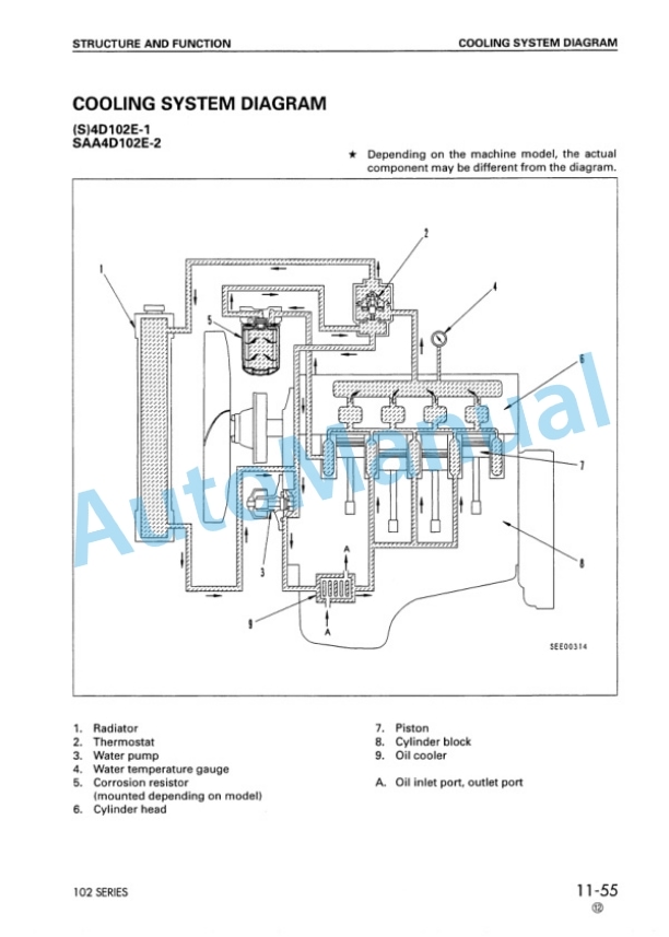
- 3.9. Cooling system
- 3.10. Check and replace alternator belt
- 3.11. Check and replace autotensioner
- 3.12. Hydraulic tank
- 3.13. Adjust mast
- 3.14. Air bleeding procedure
- 3.15. Specified fuels and lubricants
- 3.16. Lamp display of KOMTRAX terminal
- 3.17. Brake accumulator
- 3.18. Work equipment accumulator
- 4. Removal and installation
- 4.1. Weight table
- 4.2. Remove and install units
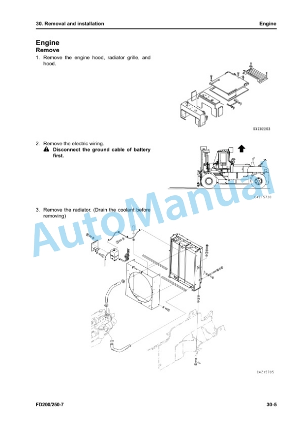
- 4.3. Engine
- 4.4. Torque converter and transmission
- 4.5. Mast
- 4.6. Lift cylinder
- 4.7. Removal and installation of KOMTRAX terminal
- 4.8. Battery
- 4.9. Wheel
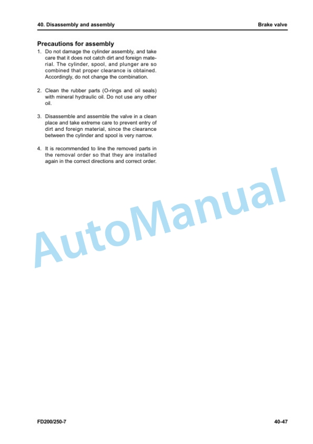
- 5. Disassembly and assembly
- 5.1. Torque converter
- 5.2. TORQFLOW transmission
- 5.3. Transmission control valve
- 5.4. Drive axle and brake
- 5.5. Work equipment control valve
- 5.6. Mast
- 5.7. Lift cylinder
- 5.8. Tilt cylinder
- 5.9. Power steering cylinder
- 5.10. Side shift cylinder
- 5.11. Disassemble lift cylinder and tilt cylinder
- 6. Maintenance standard
- 6.1. Torque converter
- 6.2. TORQFLOW transmission
- 6.3. Transmission control valve
- 6.4. Differential
- 6.5. Disc brake
- 6.6. Steering axle
- 6.7. Power steering cylinder
- 6.8. Brake valve
- 6.9. Work equipment control valve
- 6.10. Lift cylinder
- 6.11. Tilt cylinder
- 6.12. Mast, fork carriage, and fork
- 7. Structure and function
- 7.1. Torque converter
- 7.2. TORQFLOW transmission
- 7.3. Automatic transmission
- 7.4. Drive axle and brake
- 7.5. Steering system
- 7.6. Steering axle
- 7.7. Work equipment
- 7.8. Meter panel
- 7.9. Electric circuit diagram(1/2)
- 7.10. Electric circuit diagram (2/2)
- 7.11. Hydraulic circuit diagram
- 8. Yearly inspection criteria
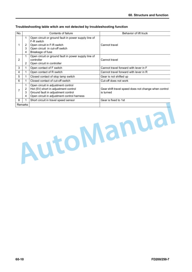
- 9. Troubleshooting
- 9.1. Check functions of troubleshooting tools and failure codes
- 9.2. Failure codes table
- 9.3. Electricalsystem failure code record display function (only for interlock controller system)
- 9.4. Troubleshooting by failure code (only for interlock controller system)
- 9.4.1. Failure code /AA10NX Air Filter Clogging
- 9.4.2. Failure code /AB00MA Alternator Malfunction
- 9.4.3. Failure code /BBAZG Engine Oil Low Oil Pressure, Speed Derated
- 9.4.4. Failure code /BBCZK Coolant Low Level
- 9.4.5. Failure Code /BCENS Torque Converter Oil Overheat
- 9.4.6. Failure code 12/DDK6KA FNR Lever Open circuit
- 9.4.7. Failure code 12/DDK6KY FNR Lever Hot Short Circuit
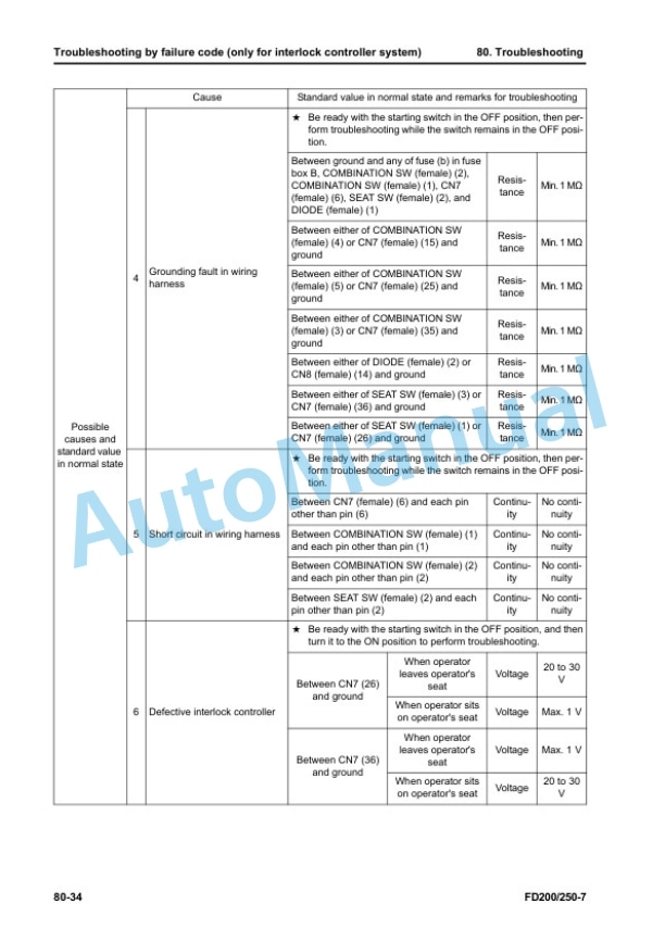
- 9.4.8. Failure code 15/7REXKA Seat Switch Open Circuit
- 9.4.9. Failure code 15/7REXKY Seat Switch Hot Short Circuit
- 9.4.10. Failure code 27/AB00KY Alternator R Signal Circuit Hot Short Circuit
- 9.4.11. Failure code 27/AB00KZ Alternator R Signal Circuit Open Circuit or Grounding Fault
- 9.4.12. Failure code 35/D110KB Battery Relay Grounding Fault
- 9.4.13. Failure code 37/DW9NLK Unload Solenoid Feedback Signal Inconsistency
- 9.4.14. Failure code 39/D140KB Starting Motor Relay Grounding Fault
- 9.4.15. Failure code 39/D140KY Starting Motor Relay Hot Short Circuit
- 9.4.16. Failure code 47/D161KA Backup Alarm Buzzer Backup Lamp Open Circuit
- 9.4.17. Failure code 47/D161KB Backup Alarm Buzzer Backup Lamp Relay Grounding Fault
- 9.4.18. Failure code 47/D161KY Backup Alarm Buzzer Backup Lamp Relay Hot Short Circuit
- 9.4.19. Failure code 48/DV00KB Alarm Buzzer Grounding Fault
- 9.4.20. Failure code 48/DV00KY Alarm Buzzer Hot Short Circuit
- 9.4.21. Failure code 52/DBM0KK Interlock Controller Power Supply Voltage Drop
- 9.4.22. Failure code 53/DBM2KK Interlock Controller Load Power Supply Voltage Drop
- 9.4.23. Failure code 54/7REHKA Accessory Input Circuit 2 (KEY_ACC_SIGNAL) Open Circuit
- 9.4.24. Failure code 56/7REAKA Accessory Input Circuit 1 (KEY_SIGNAL) Open Circuit
- 9.4.25. Failure code 62/DB2RKR CAN Communication (Between Interlock Controller and Engine Controller) Communication Error (Target Component System Error)
- 9.4.26. Failure code 63/DBM000 Interlock Controller Memory Error
- 9.4.27. Failure code 63/DBM0KT Interlock Controller Memory Error
- 9.4.28. Failure code 64/DW9KKA Forward Solenoid Valve Open Circuit
- 9.4.29. Failure code 64/DW9KKB Forward Solenoid Valve Grounding Fault
- 9.4.30. Failure code 64/DW9KKY Forward Solenoid Valve Hot Short Circuit
- 9.4.31. Failure code 65/DW9LKA Reverse Solenoid Valve Open Circuit
- 9.4.32. Failure code 65/DW9LKBReverse Solenoid Valve Grounding Fault
- 9.4.33. Failure code 65/DW9LKY Reverse Solenoid Valve Hot Short Circuit
- 9.4.34. Failure code 66/DH20KA Torque Converter Oil Temperature Sensor Open Circuit
- 9.4.35. Failure code 66/DH20KB Torque Converter Oil Temperature Sensor Grounding Fault
- 9.4.36. Failure code 67/DBM1KA Interlock Controller Select Line Open Circuit
- 9.4.37. Failure code 67/DBM1KB Interlock Controller Select Line Grounding Fault
- 9.4.38. Failure code 68/D1G1KA Unload Solenoid Relay Open Circuit
- 9.4.39. Failure code 68/D1G1KB Unload Solenoid Relay Grounding Fault
- 9.4.40. Failure code 68/D1G1KY Unload Solenoid Relay Hot Short Circuit
- 10. Index
Rate this product
You may also like
Komatsu Shop Manual PDF
$40.00

