No products in the cart.
Return to shop
$40.00
Komatsu Shop Manual PDF
Komatsu 108 Series Diesel Engine Shop Manual SEBE62210104
Komatsu 102 Series Diesel Engine Shop Manual SEBM010023
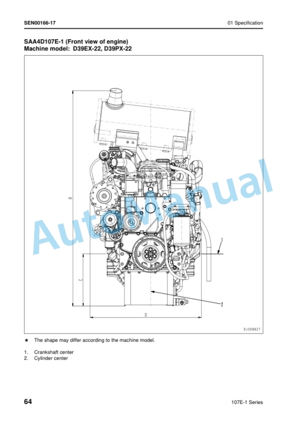
Komatsu 107E-1 Series Engine Shop Manual SEN00161-26
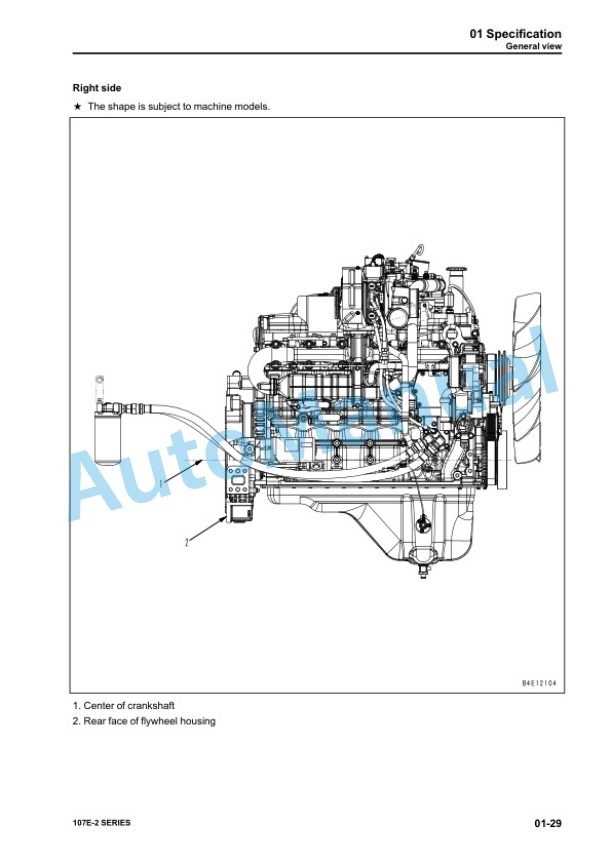
Komatsu 107E-2 Series Engine Shop Manual SEN05623-09
Komatsu 102 Series Diesel Engine Shop Manual SM140
Komatsu 102 Series Diesel Engine Shop Manual 6D102E-BE2
Komatsu 102 Series Diesel Engine Shop Manual YEBM200101
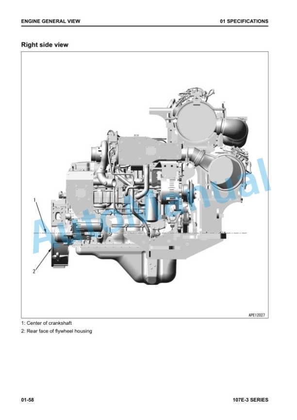
Komatsu 107E-3 Series Engine Shop Manual SEN06502-20
Komatsu 102 Series Diesel Engine Shop Manual SEBM030700
Komatsu 102 Series Diesel Engine Shop Manual 6D102E-BE1


