No products in the cart.
Return to shop
$40.00
Komatsu Shop Manual PDF
Komatsu 102 Series Diesel Engine Shop Manual SEBM030700
Komatsu 107E-1 Series Motor Shop Manual KPBM310800
Komatsu 107E-1 Series Engine Shop Manual SEN00161-26
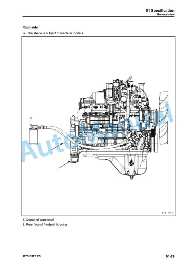
Komatsu 107E-2 Series Engine Shop Manual SEN05623-09
Komatsu 102 Series Diesel Engine Shop Manual YEBM200101
Komatsu 102 Series Diesel Engine Shop Manual SEBM010025
Komatsu 108 Series Diesel Engine Shop Manual SEBE62210103
Komatsu 102 Series Diesel Engine Shop Manual SEBM010019
Komatsu 107E-1 Series Engine Shop Manual SEN00161-27
Komatsu 102 Series Diesel Engine Shop Manual SM140


