No products in the cart.
Return to shop
$40.00
Komatsu Shop Manual PDF
Komatsu 107E-3 Series Engine Shop Manual SEN06655-01
Komatsu 107E-2 Series Engine Shop Manual SEN05623-10
Komatsu 107E-1 Series Engine Shop Manual SEN00161-28
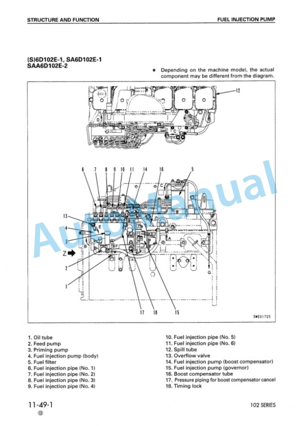
Komatsu 102 Series Diesel Engine Shop Manual SEBM010025
Komatsu 105 Series Diesel Engine Shop Manual SEBE6130A04
Komatsu 102 Series Diesel Engine Shop Manual SEBM010023
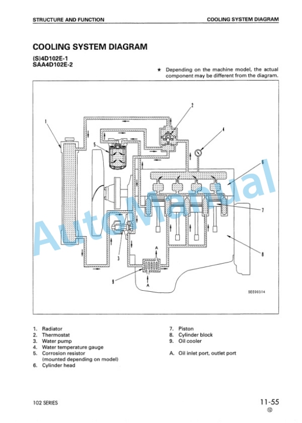
Komatsu 108 Series Diesel Engine Shop Manual SEBE62210104
Komatsu 102 Series Diesel Engine Shop Manual SEBM030700
Komatsu 107E-5 Series Engine Shop Manual SEN06896-02
Komatsu 107E-3 Series Engine Shop Manual SEN06502-11


