- Claas
- Grove
- New Holland
- Komatsu
- Kubota
- John Deere
- Linde
- Bomag
- CASE
- Clark
- JCB
- Jungheinrich
- Linde
- Yale
- Yanmar
- Manitou
- Manitowoc
- CNH
- Doosan
- Fiatagri
- Fiatallis
- Fiatallis Other Manual PDF
- Flexi Coil
- Ford New Holland
- Ford New Holland Other Manual PDF
- Huyndai
- Hypac
- Hyster
- Hyster Service Manual PDF
- Isuzu
- Kobelco
- Kohler
- Krupp
- Lombardini
- Mahindra
- Nuvera
- Perkins
- Sperry New Holland
- Utilev
- Versatile
- ZF


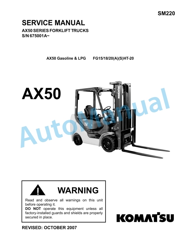
Komatsu MWL22-2A Forklift Truck Service Manual
$30.00
- Type Of Manual: Service Manual
- Format: PDF
- Size: 3.1MB
- Number of Pages: 250
Category: Komatsu Service Manual PDF
-
Model List:
- MWL22-2A Forklift Truck
- 1. BYINTRO
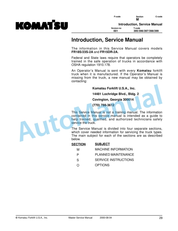
- 1.1. Introduction, Service Manual
- 1.2. Contents, Section M
- 1.2.1. Machine Information
- 1.3. General Product Information
- 1.3.1. Truck Presentation.
- 1.3.1.1. Truck Side Views
- 1.3.1.2. Intended Truck Application
- 1.3.1.3. Prohibited Truck Application
- 1.3.1.4. Truck Data
- 1.3.1.5. Truck Dimensions
- 1.3.1.6. Data Plate
- 1.3.2. Main Components
- 1.4. Inch and Metric (SAE) Fasteners
- 1.4.1. Introduction
- 1.4.2. Nomenclature, Threads
- 1.4.3. Strength Identification
- 1.4.4. Conversion of English and Metric Units
- 2. BYBRAKE
- 2.1. Parking Brake System
- 2.1.1. Brake Theory of Operation
- 2.1.2. Brake Adjustment
- 2.1.3. Brake Shoe Removal / Installation
- 2.2. Drive Wheel
- 2.2.1. Removal
- 2.2.2. Installation
- 2.2.3. Tire Pressing Procedure
- 2.3. Support/Swivel Wheel (Optional)
- 2.3.1. Maintenance and Adjustments
- 2.3.1.1. Caster Adjustment
- 2.3.2. Troubleshooting
- 2.3.2.1. Stabilizing Caster
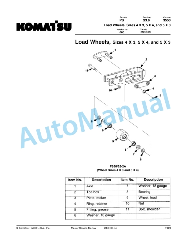
- 2.4. Fork Wheels
- 2.4.1. Removal/Installation
- 2.5. Steering
- 2.5.1. Control Handle Head
- 2.5.1.1. Removal
- 2.5.1.2. Installation
- 2.5.2. Driver Protection (Reverser) Assembly Replacement
- 2.5.3. Direction Control Switches
- 2.5.3.1. Removal
- 2.5.3.2. Installation
- 2.5.4. Raise, Lower, and Horn Switches
- 2.6. Electrical Functions
- 2.6.1. General
- 2.6.1.1. Adjustable Settings
- 2.6.1.2. References
- 2.6.1.3. Key Switch S17 in the ON Position
- 2.6.1.4. Operating Arm in Drive Position, S10, Brake Switch Closed
- 2.6.1.5. Travel Request, Fork First
- 2.6.1.6. Travel Request, Forks Trailing
- 2.6.1.7. Reversing/Motor Brake Forks First Direction to Forks Trailing Direction
- 2.6.1.8. Reversing/Motor Brake Forks Trailing Direction to Forks First Direction
- 2.6.1.9. Reverser switch
- 2.6.1.10. Lifting Forks
- 2.6.1.11. Lowering Forks
- 2.6.1.12. Horn
- 2.6.1.13. Lift Interrupt
- 2.7. Electrical Panel Components
- 2.8. Electrical Symbols
- 2.9. Electrical Schematics
- 2.10. Battery
- 2.10.1. Removal
- 2.10.2. Installation
- 2.10.3. Battery Maintenance
- 2.10.3.1. Battery Inspection and Care
- 2.10.3.2. Battery Exterior Cleaning
- 2.10.3.3. Charging
- 2.10.4. Storage
- 2.10.5. Battery History Record
- 2.11. Swing Out Battery Pack
- 2.11.1. Battery Cable Routing Diagram
- 2.11.2. Charger Diagram
- 2.11.3. Troubleshooting
- 2.11.3.1. Electrical Testing
- 2.12. Battery Connector
- 2.12.1. Location
- 2.12.2. Inspection
- 2.12.3. Installation
- 2.13. Battery Controller/Hourmeter/ Lift Interrupt (Optional)
- 2.13.1. General Information
- 2.13.2. Electrical
- 2.13.2.1. Voltage
- 2.13.3. Battery Controller (BC)
- 2.13.3.1. General Information
- 2.13.3.2. Reset
- 2.13.3.3. Key Switch
- 2.13.3.4. Hourmeter
- 2.13.4. Troubleshooting
- 2.13.4.1. Battery Discharge Indicator (BDI)
- 2.13.4.2. Hourmeter
- 2.14. Battery Discharge Indicator/ Hourmeter
- 2.14.1. General Information
- 2.14.2. Electrical
- 2.14.2.1. Voltage
- 2.14.3. Battery Discharge Indicator (BDI)
- 2.14.3.1. General Information
- 2.14.3.2. Key Switch
- 2.14.3.3. Hourmeter
- 2.14.4. Troubleshooting
- 2.14.4.1. Battery Discharge Indicator (BDI)
- 2.14.4.2. Hourmeter
- 2.15. Start/Stop Switches
- 2.15.1. General
- 2.15.1.1. Test/Inspection
- 2.15.2. Master Control On/Off Switch (S21)
- 2.15.2.1. Inspection
- 2.15.2.2. Removal
- 2.15.2.3. Installation
- 2.16. Transistor Controller
- 2.16.1. Basics Of Circuit Operation
- 2.16.1.1. Control Features
- 2.16.2. Maintenance
- 2.16.2.1. Safety
- 2.16.2.2. Cleaning
- 2.16.3. Motor Circuit
- 2.16.4. Control Circuit
- 2.16.5. Troubleshooting Guidelines
- 2.16.5.1. General
- 2.16.6. Shorts to Frame Test
- 2.16.7. Definitions
- 2.16.8. Diagnostics and Troubleshooting
- 2.16.8.1. Handset Diagnostics
- 2.16.8.2. Troubleshooting
- 2.16.8.3. Troubleshooting Chart
- 2.16.8.4. Technical Specification
- 2.16.8.5. Troubleshooting Chart Using Handset
- 2.17. Transistor Controller Troubleshooting
- 2.17.1. Troubleshooting Chart Index
- 2.17.2. Troubleshooting Charts
- 3. BYHYDRA
- 3.1. Hydraulic System
- 3.1.1. General
- 3.1.2. Troubleshooting
- 3.1.3. Schematic
- 3.1.4. Description
- 3.1.4.1. Lift
- 3.1.4.2. Lower
- 3.1.4.3. Relief Pressure
- 3.1.5. Maintenance
- 3.1.6. Lift Limit Switch
- 3.1.6.1. Solenoid Operated Valve
- 3.2. Lift Cylinder
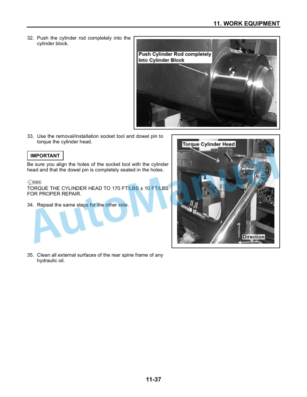
- 3.2.1. Cylinder Repair
- 3.3. Battery Charger, Optima Pack
- 3.4. Handset Operation
- 3.4.1. Operating Modes
- 3.4.2. Revert to Previous Settings
- 3.4.3. Handset Self Test
- 4. BYMAINT
- 4.1. Technical Service Data
- 4.2. Ordering Spare Parts
- 4.3. Contents, Section P
- 4.3.1. Planned Maintenance
- 4.4. Introduction, Maintenance
- 4.4.1. Jacking Truck Off The Floor
- 4.4.1.1. Elevate Rear of Truck
- 4.4.1.2. Elevate Either Side of Truck
- 4.4.2. Lubricants
- 4.4.2.1. Standard
- 4.4.2.2. Corrosion
- 4.4.3. Cold Storage
- 4.5. Service Schedule
- 4.5.1. Planned Maintenance Schedule
- 4.5.2. Planned Maintenance Procedures
- 4.5.2.1. Services Performed Daily or Every 8 Operating Hours
- 4.5.2.2. Services Performed Monthly or Every 120 Operating Hours
- 4.5.2.3. Services Performed Every 480 or 960 Operating Hours
- 4.5.2.4. Services Performed Annually or Every 1440 Operating Hours
- 4.6. Lubrication Chart
- 4.7. Oil and Grease Specifications
- 4.7.1. Approved Oils and Grease
- 4.7.2. Grease Location Points
- 5. BYMOTOR
- 5.1. Pump Motor
- 5.1.1. Mounting Points
- 5.1.1.1. Removal
- 5.1.1.2. Installation
- 5.1.2. Pump Repair
- 5.1.2.1. Disassembly
- 5.1.3. Inspection and Troubleshooting
- 5.1.3.1. Drive End Head
- 5.1.3.2. Commutator End Head
- 5.1.3.3. Bearings
- 5.1.4. Brush Inspection
- 5.1.4.1. Brush Replacement Determination
- 5.1.4.2. Replacement Procedures
- 5.2. Drive Motor
- 5.2.1. Mounting Points
- 5.2.1.1. Drive Motor Brush
- 5.2.1.2. Drive Motor Removal
- 5.2.1.3. Drive Motor Installation
- 5.2.2. Component Repair
- 5.2.2.1. Motor Disassembly
- 5.2.3. Motor Inspection
- 5.2.3.1. External Motor
- 5.2.3.2. Brush and Commutator
- 5.2.3.3. Bearings
- 5.2.3.4. Armature Electrical Check
- 5.2.3.5. Frame and Field Service Recommendation
- 5.2.3.6. Assembly/Testing
- 5.3. Transmission
- 5.3.1. System Description
- 5.3.2. Troubleshooting
- 5.3.3. Transmission Mounting
- 5.3.3.1. Wrap Around Bumper
- 5.3.3.2. Guards
- 5.3.3.3. Removal
- 5.3.3.4. Installation
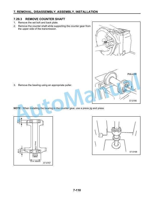
- 5.3.4. Transmission Repair
- 5.4. Warning Symbols
- 5.4.1. Warning Levels
- 5.5. Prohibitory Symbols
- 5.5.1. Ordinance Symbols
- 5.6. Contents, Section S
- 5.6.1. Service Instructions
- 5.7. Chassis/Lift Frame
- 5.7.1. Pull rod
- 5.7.1.1. Removal
- 5.7.1.2. Inspection
- 5.7.1.3. Installation
- 5.7.2. Carrier Frame Bushings
- 5.8. Inspection Covers
- 5.8.1. General Information
- 5.9. Driver Controls
- 5.10. Decals
- 5.10.1. Decal with Protective Sheet
- 5.10.2. Decal without Protective Sheet
- 5.11. Motor Maintenance Schedule/ Troubleshooting
- 5.11.1. General Information
- 5.11.2. Operating Conditions
- 5.11.3. Troubleshooting
Rate this product
You may also like
Komatsu Service Manual PDF
Komatsu FR18S-2A, FR23S-2A, FR15DR-2A Forklift Truck Service Manual
$30.00
Komatsu Service Manual PDF
$30.00
Komatsu Service Manual PDF
$30.00
Komatsu Service Manual PDF
Komatsu 4TNE94.98.106T Diesel Engine Service Manual HINSHI-H8013-R1
$30.00
Komatsu Service Manual PDF
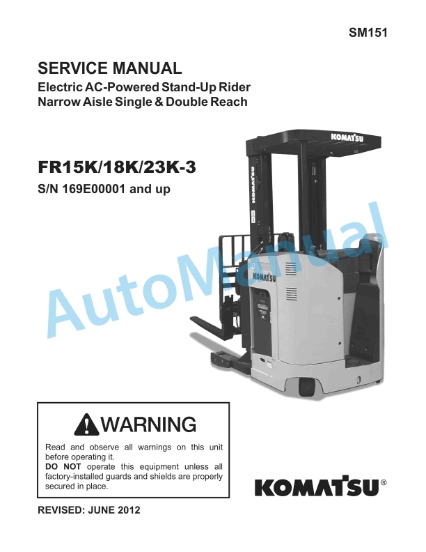
Komatsu FR15K-3, FR18K-3, FR23K-3 Electric AC-Powered Stand-Up Rider Service Manual SM151
$30.00
Komatsu Service Manual PDF
$30.00
Komatsu Service Manual PDF
Komatsu CX50 Forklift Truck EPA Tier 3 Compliant Service Manual SM204
$30.00
Komatsu Service Manual PDF
$30.00
Komatsu Service Manual PDF
$30.00
- Claas
- Grove
- New Holland
- Komatsu
- Kubota
- John Deere
- Linde
- Bomag
- CASE
- Clark
- JCB
- Jungheinrich
- Linde
- Yale
- Yanmar
- Manitou
- Manitowoc
- CNH
- Doosan
- Fiatagri
- Fiatallis
- Fiatallis Other Manual PDF
- Flexi Coil
- Ford New Holland
- Ford New Holland Other Manual PDF
- Huyndai
- Hypac
- Hyster
- Hyster Service Manual PDF
- Isuzu
- Kobelco
- Kohler
- Krupp
- Lombardini
- Mahindra
- Nuvera
- Perkins
- Sperry New Holland
- Utilev
- Versatile
- ZF