Komatsu PC1250-11, PC1250-11E0, PC1250LC-11, PC1250LC-11E0, PC1250SP-11, PC1250SP-11E0 Hydraulic Excavator Field Assembly Instruction GEN00203-08
$20.00
- Type Of Manual: Field Assembly Instruction
- Manual ID: GEN00203-08
- Format: PDF
- Size: 41.0MB
- Number of Pages: 293
-
Model List:
- PC1250-11 Hydraulic Excavator
- PC1250-11E0 Hydraulic Excavator
- PC1250LC-11 Hydraulic Excavator
- PC1250LC-11E0 Hydraulic Excavator
- PC1250SP-11 Hydraulic Excavator
- PC1250SP-11E0 Hydraulic Excavator
- 1. FOREWORD
- 2. CONTENTS
- 3. SPECIFICATIONS
- 4. PRECAUTIONS FOR FIELD ASSEMBLY
- 5. ASSEMBLING PROCEDURES, APPLICABLE EQUIPMENT AND SCHEDULE
- 6. KIT LAYOUT DIAGRAM
- 7. FLOW OF FIELD ASSEMBLY WORK
- 8. TRANSPORTATION
- 9. LIST OF FIELD ASSEMBLY TOOLS
- 10. TIGHTENING TORQUE
- 11. COATING MATERIALS
- 12. SELECTION OF WIRE ROPES USED FOR ASSEMBLY
- 13. ASSEMBLY OF CHASSIS
- 13.1. A1 Install R.H. and L.H. track frames
- 13.2. A2 Install travel piping
- 13.3. A3 Install travel piping covers
- 13.4. A4 Install steps
- 13.5. A5 Install autogreasing unit assembly(if equipped)
- 13.6. A6 Add grease to swing circle
- 13.7. A7 Assemble upper structure and undercarriage
- 13.8. A8 Install R.H. side step
- 13.9. A9 Install handrails
- 13.10. A10 Install emergency stop switch on right front step (if equipped)
- 13.11. A11 Install air cleaner cap
- 13.12. A12 Install swivel travel piping
- 13.13. A13 Install crawler undercover
- 13.14. A14 Install L.H. side step
- 13.15. A15 Install L.H. side step (Machine with high cab (if equipped))
- 13.16. A16 Install fixed ladder
- 13.17. A17 Install hydraulic stairway (if equipped)
- 13.18. A18 Install flash light (if equipped)
- 13.19. A19 Install L.H. side step emergency stop switch (if equipped)
- 13.20. A20 Install KomVision camera
- 13.21. A21 Install counterweight
- 13.22. A22 Install counterweight revolving warning lamp (if quipped)
- 13.23. A23 Install counterweight rear lamp (if equipped)
- 13.24. A24 Install radiator cover
- 13.25. A25 Install exhaust tail pipe
- 13.26. A26 Subassembly on top guard
- 13.27. A27 Installation of top guard
- 13.28. A28 Installation of cab
- 13.29. A29 Assembly of parts inside cab
- 13.30. A30 Change installed position of step light
- 13.31. A31 Change installed position of wireless LAN antenna
- 13.32. A32 Install operators cab revolving warning lamp (if equipped)
- 13.33. A33 Install operators cab handrail
- 13.34. A34 Install L.H. rearview mirror
- 13.35. A35 Install R.H. rearview mirror
- 13.36. A36 Prepare for bleeding air from travel motor
- 13.37. A37 Bleed air from hydraulic pump section
- 13.38. A38 Tighten swing circle mounting bolts to specified torque
- 13.39. A39 Check and adjust track tension
- 13.40. A40 Check fuel, coolant and oil levels
- 13.41. A41 Parts to be touched up after field assembly
- 14. ASSEMBLING OF WORK EQUIPMENT OF BACKHOE
- 14.1. B1 Release remaining pressure in hydraulic circuit
- 14.2. B2 Install arm cylinder to boom
- 14.3. B3 Install arm cylinder hose
- 14.4. B4 Install boom cylinder to revolving frame
- 14.5. B5 Install boom cylinder hose
- 14.6. B6 Bleed air from cylinder
- 14.7. B7 Install boom foot dust seal
- 14.8. B8 Install boom assembly
- 14.9. B9 Install boom cylinder to boom assembly
- 14.10. B10 Install boom connection hoses (between chassis and boom assembly)
- 14.11. B11 Install arm assembly
- 14.12. B12 Install bucket cylinder hoses (between boom and bucket cylinder)
- 14.13. B13 Install bucket assembly
- 14.14. B14 Clearance standard for installation of work equipment
- 14.15. B15 Install work equipment grease piping
- 14.16. B16 Install work equipment lamps
- 14.17. B17 Grease after assembling work equipment
- 14.18. B18 Bleed air from swing motor
- 14.19. B19 Bleed air from travel motor
- 14.20. B20 Install travel motor guard
- 14.21. B21 Bleed air from hydraulic stairway (if equipped)
- 15. PROCEDURE FOR INSPECTION AND MAINTENANCE AFTER COMPLETION ASSEMBLY
- 15.1. M1 Replace return filter (Replace standard filter flushing filter)
- 15.2. M2 Flush hydraulic circuit
- 15.3. M3 Replace return filter (Replace flushing filter with standard filter)
- 15.4. M4 Replace pilot filter
- 15.5. M5 Setting of KomVision (Camera calibration)
- 15.6. M6 Inspection method of 12 m visibility (KomVision)
- 15.7. M7 Method for starting up KOMTRAX terminal and default setting of KOMTRAX Plus controller
- 16. PROCEDURE FOR ASSEMBLING WORK EQUIPMENTOF LOADING SHOVEL
- 16.1. TRANSPORTATION POSTURE (ONLY WORK EQUIPMENT)
- 16.2. C 1. Release remaining pressure in hydraulic circuit
- 16.3. C 2. Bleed air from cylinder
- 16.4. C 3. Flush hydraulic circuit
- 16.5. C 4. Installation of Arm Cylinder Bottoms
- 16.6. C 5. Connection of Boom and Arm
- 16.7. C 6. Pulling out Boom Foot Pin and Boom Cylinder Foot Pin
- 16.8. C 7. Installation of Boom and Arm Assembly
- 16.9. C 8. Installation of Boom Hoses (Between Chassis and Boom)
- 16.10. C 9. Installation of Hoses Between Boom and Arm (Bottom Dump)
- 16.11. C10. Installation of Boom Cylinder Bottoms
- 16.12. C11. Installation of Boom Cylinder Hoses
- 16.13. C12. Installation of Boom Cylinder Head Pin
- 16.14. C13. Installation of Arm Cylinder Hoses
- 16.15. C14. Installation of Bucket Cylinder
- 16.16. C15. Installation of Bucket Cylinder Hoses
- 16.17. C16. Installation of Bucket Assembly
- 16.18. C17. Installation of Bottom Dump Cylinder Hoses
- 16.19. C18. Maintenance Standard
- 16.20. C19. Installation of Working Lamp
- 16.21. C20. Installation of Work Equipment Greasing Piping
- 16.22. C21. Checking Oil Level in Hydraulic Tank and Adding Oil
- 16.23. C22. Greasing After Assembling Work Equipment
- 17. INSPECTION OF EACH PART AFTER ASSEMBLY OF LOADER
- 18. FIELD ASSEMBLY INSPECTION REPORT
- 19.
Komatsu Operation and Maintenance Manual PDF
Komatsu 101 Basics Forklift Truck Operation and Maintenance Manual
Komatsu Operation and Maintenance Manual PDF
Komatsu 730E Dump Truck Operation and Maintenance Manual CEAM014901
Komatsu Operation and Maintenance Manual PDF
Komatsu 730E Dump Truck Operation and Maintenance Manual CEAM011001
Komatsu Operation and Maintenance Manual PDF
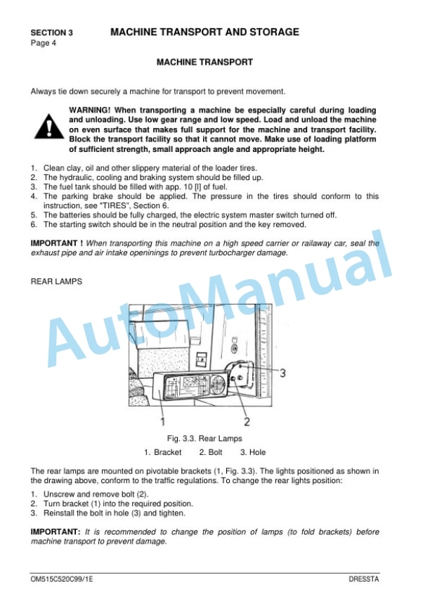
Komatsu 515C, 520C Operation and Maintenance Manual OM515C520C99-1E
Komatsu Operation and Maintenance Manual PDF
Komatsu 210M Dump Truck Operation and Maintenance Manual DG615
Komatsu Operation and Maintenance Manual PDF
Komatsu 4D104E, S4D104E Series Diesel Motor Operation and Maintenance Manual WHBMNEF000
Komatsu Operation and Maintenance Manual PDF
Komatsu 210M Dump Truck Operation and Maintenance Manual DG725
Komatsu Operation and Maintenance Manual PDF
Komatsu 730E Dump Truck Operation and Maintenance Manual CEAM013300
Komatsu Operation and Maintenance Manual PDF
Komatsu 730E Dump Truck Operation and Maintenance Manual CEAM011200
Komatsu Operation and Maintenance Manual PDF
Komatsu 410W Hydraulic Excavator Operation and Maintenance Manual UMGB410W1