Komatsu PC2000-8 Hydraulic Excavator Field Assembly Instruction GEN00060-13
$20.00
- Type Of Manual: Field Assembly Instruction
- Manual ID: GEN00060-13
- Format: PDF
- Size: 27.3MB
- Number of Pages: 332
-
Model List:
- PC2000-8 Hydraulic Excavator
- 1. COVER
- 2. FOREWORD
- 3. CONTENTS
- 4. SPECIFICATIONS
- 5. PRECAUTIONS FOR FIELD ASSEMBLY
- 6. DISPOSAL OF REMOVED PARTS
- 7. ASSEMBLY PROCEDURE, ASSEMBLY EQUIPMENT AND SCHEDULE
- 8. FLOWCHART OF MAIN ASSEMBLY PROCEDURE
- 9. KIT LAYOUT DIAGRAM
- 10. TRANSPORTATION POSTURES
- 11. LIST OF PARTS SENT INDIVIDUALLY
- 12. TOOLS AND EQUIPMENT TO BE USED FOR LOCAL ASSEMBLY
- 13. TIGHTENING TORQUE
- 14. COATING MATERIALS LIST
- 15. ASSEMBLY OF CHASSIS
- 15.1.
- 15.1.1. A 1. Assembly of track frame assembly and center frame assembly
- 15.1.2. A 2. Installation of idler cushion cylinder piping
- 15.1.3. A 3. Installation of travel motor piping
- 15.1.4. A 4. Installation of travel motor cover
- 15.1.5. A 5. Filling swing circle with grease
- 15.1.6. A 6. Assembly of revolving frame assembly and undercarriage
- 15.1.7. A 7. Installation of swing machinery (front) assembly (27t), Installation of swing motor (front) assembly (32t)
- 15.1.8. A 8. Connection of swivel joint piping
- 15.1.9. A 9. Connection of swing circle grease piping
- 15.2.
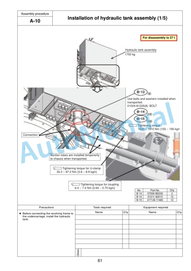
- 15.2.1. A10. Installation of hydraulic tank assembly
- 15.2.2. A11. Installation of fuel tank assembly
- 15.2.3. A12. Connection of fuel tank assembly piping and wiring
- 15.2.4. A13. Installation of cab base assembly
- 15.2.5. A14. Installation of emergency escape ladder
- 15.2.6. A15. Installation of left floor assembly
- 15.2.7. A16. Connection of cab base assembly piping
- 15.2.8. A17. Connection of cab base assembly wiring
- 15.2.9. A18. Connection of left floor assembly heater piping
- 15.3.
- 15.3.1. A19. Connection of left floor assembly wiring
- 15.3.2. A20. Installation of tail pipe
- 15.3.3. A21. Installation of power container assembly
- 15.3.4. A22. Connection of suction piping
- 15.3.5. A23. Connection of oil cooler piping and pump drain piping
- 15.3.6. A24. Connection of fan motor drain piping
- 15.3.7. A25. Installation of suction unit undercover
- 15.3.8. A26. Connection of delivery piping
- 15.3.9. A27. Connection of pilot piping and fan motor piping
- 15.3.10. A28. Connection of power container assembly fuel piping
- 15.3.11. A29. Connection of power container assembly air conditioner piping
- 15.3.12. A30. Connection of power container assembly heater piping
- 15.3.13. A31. Connection of power container assembly wiring
- 15.4.
- 15.4.1. A32. Installation of operators cab assembly
- 15.4.2. A33. Installation of rotary lamp (if equipped)
- 15.4.3. A34. Installation of ORBCOMM antenna (if equipped)
- 15.4.4. A35. Connection of operators cab assembly wiring
- 15.4.5. A36. Connection of operators cab assembly hydraulic piping
- 15.4.6. A37. Connection of operators cab assembly window washer hose
- 15.4.7. A38. Connection of operators cab assembly air conditioner piping
- 15.4.8. A39. Connection of operators cab assembly heater piping
- 15.4.9. A40. Installation of operators cab rear floor assembly
- 15.4.10. A41. Installation of handrail around operators cab
- 15.5.
- 15.5.1. A42. Installation of track frame ladder
- 15.5.2. A43. Installation of power container side catwalk assemblies (right and left)
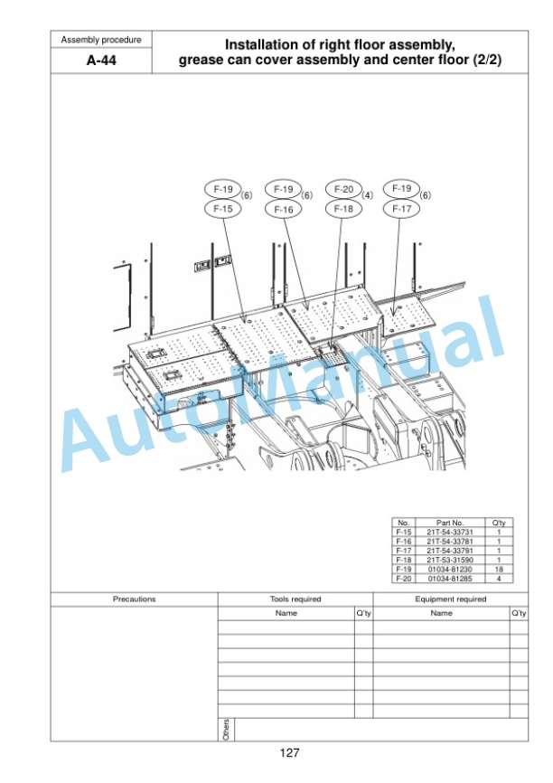
- 15.5.3. A44. Installation of right floor assembly, grease can cover assembly and center floor
- 15.5.4. A45. Installation of fuel tank right catwalk assembly
- 15.5.5. A46. Installation of fuel tank front catwalk assembly
- 15.5.6. A47. Adjustment of exterior parts clearance
- 15.5.7. A48. Connection of grease reel piping
- 15.5.8. A49. Installation of access ladder assembly
- 15.5.9. A50. Installation of counterweight assembly
- 15.5.10. A51. Installation of deformation preventing stoppers for catwalk assemblies (left and right) on the side of power container
- 15.5.11. A52. Installation of handrail on counterweight
- 15.5.12. A53. Installation of handrail clamps
- 15.5.13. A54. Connection of fuel cut wire
- 15.5.14. A55. Connection of drain piping under power container
- 15.5.15. A56. Connection of battery wiring
- 15.6.
- 15.6.1. A57. Setting of hydraulic tank strainer
- 15.6.2. A58. Starting engine, checking oil and coolant levels, bleeding air from each part, and adjusting track
- 15.6.3. A59. Permanent tightening of swing circle bolt
- 15.6.4. A60. Parts to be touched up after field assembly (chassis side)
- 15.6.5. A61. Connection of engine heater connection port
- 15.6.6. A62. Installation of optional harness
- 15.6.7. A63. Installation of rear lamps
- 15.6.8. A64. Installation of rear camera
- 15.6.9. A65. Connection of emergency stop switch (if equipped) (at the right below container)
- 15.6.10. A66. Connection of emergency stop switch (if equipped) (at the left side of ladder)
- 15.6.11. A67. Installation of engine oil and PTO oil pipings
- 15.6.12. A68. Installation of coolant piping
- 15.6.13. A69. Installation of guard bracket (if equipped)
- 16. ASSEMBLY OF BACKHOE
- 16.1.
- 16.1.1. C 1. Installation of boom cylinder
- 16.1.2. C 2. Installation of boom cylinder hoses (Serial No. 20095 and up)
- 16.1.3. C 3. Assembly of boom sub assembly
- 16.1.4. C 4. Installation of boom assembly
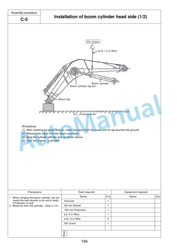
- 16.1.5. C 5. Installation of boom cylinder head side
- 16.2.
- 16.2.1. C 6. Installation of hoses between boom and chassis
- 16.2.2. C 7. Installation of arm assembly
- 16.2.3. C 8. Installation of arm cylinder
- 16.2.4. C 9. Connection of hoses between boom and arm
- 16.2.5. C10. Connection of auto grease piping
- 16.2.6. C11. Connection of wiring between boom and chassis
- 16.3.
- 16.3.1. C12. Installation of bucket assembly
- 16.3.2. C13. Installation of bucket link
- 16.3.3. C14. Bleeding air from cylinders
- 16.3.4. C15. Parts to be touched up after field assembly (work equipment side)
- 16.3.5. C16. Bleeding air from auto grease circuit
- 17. LS. ASSEMBLY OF LOADING SHOVEL WORK EQUIPMENT
- 17.1. LS 1. Installation of arm cylinder bottom parts
- 17.2. LS 2. Installation of boom cylinder to machine body
- 17.3. LS 3. Installation of boom cylinder hoses
- 17.4. LS 4. Installation of boom cylinder piping
- 17.5. LS 5. Installation of boom assembly
- 17.6. LS 6. Installation of boom cylinder head pins
- 17.7. LS 7. Installation of hose between machine body and boom
- 17.8. LS 8. Installation of bucket cylinder assembly
- 17.9. LS 9. Installation of arm assembly
- 17.10. LS10. Installation of arm cylinder assembly
- 17.11. LS11. Installation of hoses between boom and arm
- 17.12. LS12. Installation of bucket cylinder hoses
- 17.13. LS13. Installation of grease feed hose of bucket cylinder
- 17.14. LS14. Installation of bucket assembly
- 17.15. LS15. Installation of arm cylinder junction hoses
- 17.16. LS16. Installation of bottom dump hose and grease feed hose between arm and bucket
- 17.17. LS17. Installation of arm dump cushion (proximity switch)
- 18. INSPECTION AND SERVICING PROCEDURES AFTER ASSEMBLY
- 18.1. M 1. Inspection of oil levels and coolant levels and using standard of fuel and lubricant
- 18.2. M 2. Flushing of hydraulic circuit
- 18.3. M 3. Releasing residual pressure from hydraulic circuit
- 18.4. M 4. Releasing residual pressure from HIC circuit and check of gas pressure in HIC accumulator
- 18.5. M 5. Charging air conditioner with refrigerant
- 18.6. M 6. Installed angles of mirrors
- 18.7. M 7. Installed angles of lights
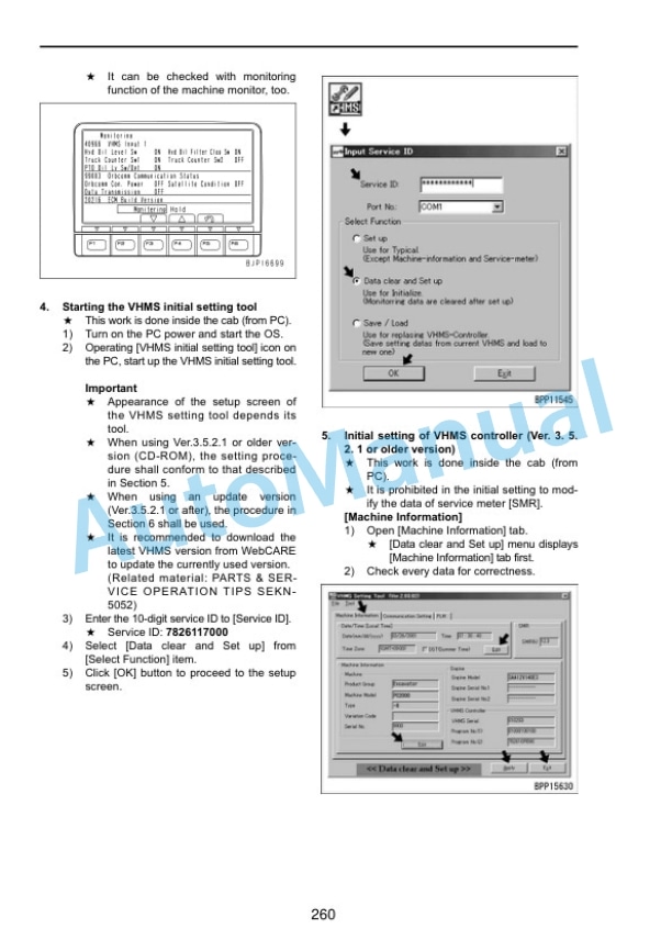
- 19. VHMS CONTOROLLER INITIAL SETTING PROCEDURE
- 20. PC20008 Main pump air bleeding check sheet
- 21. FIELD ASSEMBLY INSPECTION REPORT (BACKHOE)
- 22. FIELD ASSEMBLY INSPECTION REPORT (LOADING SHOVEL)
Komatsu Operation and Maintenance Manual PDF
Komatsu 430FX-1, 430FXL-1, 445FXL-1 Operation and Maintenance Manual CEAM023702
Komatsu Operation and Maintenance Manual PDF
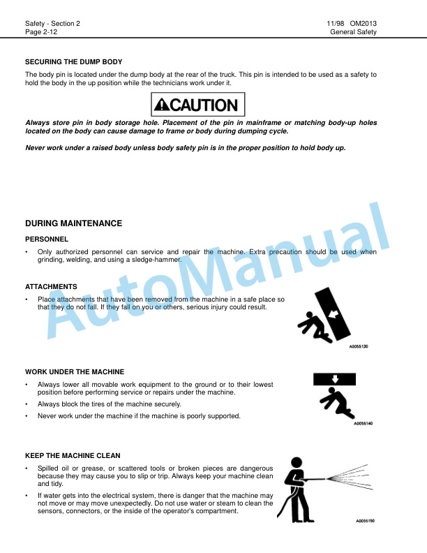
Komatsu 330M Dump Truck Operation and Maintenance Manual DG745
Komatsu Operation and Maintenance Manual PDF
Komatsu 503 Motor Grader Operation and Maintenance Manual 2079A-H45
Komatsu Operation and Maintenance Manual PDF
Komatsu 730E Dump Truck Operation and Maintenance Manual CEAM018100
Komatsu Operation and Maintenance Manual PDF
Komatsu 4D104E, S4D104E Series Diesel Motor Operation and Maintenance Manual WHBMNEF000
Komatsu Operation and Maintenance Manual PDF
Komatsu 210M Dump Truck Operation and Maintenance Manual DG615
Komatsu Operation and Maintenance Manual PDF
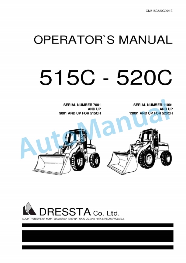
Komatsu 515C, 520C Operation and Maintenance Manual OM515C520C99-1E
Komatsu Operation and Maintenance Manual PDF
Komatsu 730E Dump Truck Field Assembly Instruction CEAW004103
Komatsu Operation and Maintenance Manual PDF
Komatsu 101 Basics Forklift Truck Operation and Maintenance Manual
Komatsu Operation and Maintenance Manual PDF
Komatsu 210M Dump Truck Operation and Maintenance Manual DG725

