No products in the cart.
Return to shop
$40.00
Komatsu Shop Manual PDF
Komatsu 107E-2 Series Engine Shop Manual SEN05623-09
Komatsu 102 Series Diesel Engine Shop Manual SEBM010019
Komatsu 102 Series Diesel Engine Shop Manual 6D102E-BE1
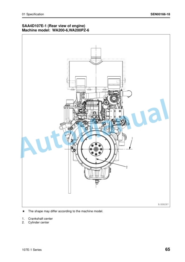
Komatsu 107E-1 Series Engine Shop Manual SEN00161-27
Komatsu 108 Series Diesel Engine Shop Manual SEBE62210103
Komatsu 107E-1 Series Engine Shop Manual SEN00161-26
Komatsu 102 Series Diesel Engine Shop Manual 6D102E-BE2
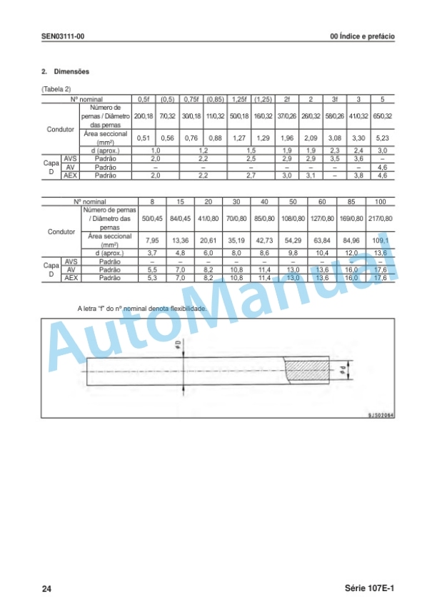
Komatsu 107E-1 Series Motor Shop Manual KPBM310800
Komatsu 102 Series Diesel Engine Shop Manual SEBM010026
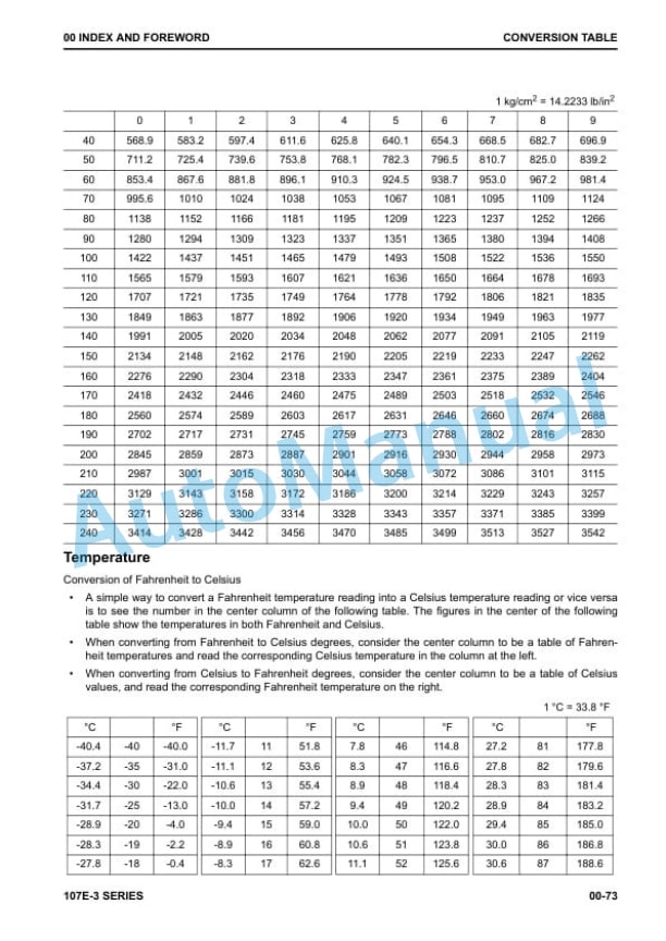
Komatsu 107E-3 Series Engine Shop Manual SEN06655-00


