- Claas
- Grove
- New Holland
- Komatsu
- Kubota
- John Deere
- Linde
- Bomag
- CASE
- Clark
- JCB
- Jungheinrich
- Linde
- Yale
- Yanmar
- Manitou
- Manitowoc
- CNH
- Doosan
- Fiatagri
- Fiatallis
- Fiatallis Other Manual PDF
- Flexi Coil
- Ford New Holland
- Ford New Holland Other Manual PDF
- Huyndai
- Hypac
- Hyster
- Hyster Service Manual PDF
- Isuzu
- Kobelco
- Kohler
- Krupp
- Lombardini
- Mahindra
- Nuvera
- Perkins
- Sperry New Holland
- Utilev
- Versatile
- ZF


Komatsu SAA4D95LE-5, S4D95LE-3 Diesel Engine Shop Manual 4D95LE-BE4
$40.00
- Type Of Manual: Shop Manual
- Manual ID: 4D95LE-BE4
- Format: PDF
- Size: 62.4MB
- Number of Pages: 613
Category: Komatsu Shop Manual PDF
-
Model List:
- SAA4D95LE-5 Diesel Engine
- S4D95LE-3 Diesel Engine
- 1. EBE4
- 1.1. Index and foreword
- 1.1.1. Index and foreword
- 1.1.1.1. Composition of shop manual
- 1.1.1.2. Table of contents
- 1.1.1.3. Safety notice
- 1.1.1.4. How to read the shop manual
- 1.1.1.5. Explanation of terms for maintenance standard
- 1.1.1.6. Handling of electric equipment and hydraulic component
- 1.1.1.7. Handling of connectors newly used for engines
- 1.1.1.8. How to read electric wire code
- 1.1.1.9. Precautions when carrying out operation
- 1.1.1.10. Method of disassembling and connecting pushpull type coupler
- 1.1.1.11. Standard tightening torque table
- 1.1.1.12. Conversion table
- 1.2. Specification
- 1.2.1. Specification
- 1.2.1.1. Outline
- 1.2.1.2. Specifications
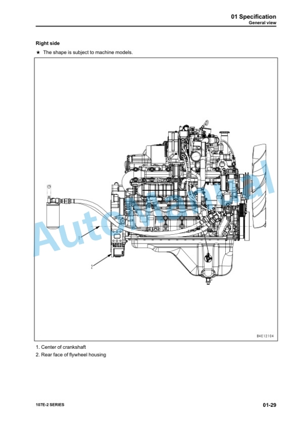
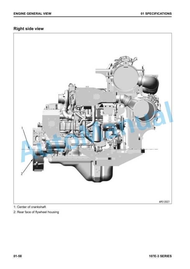
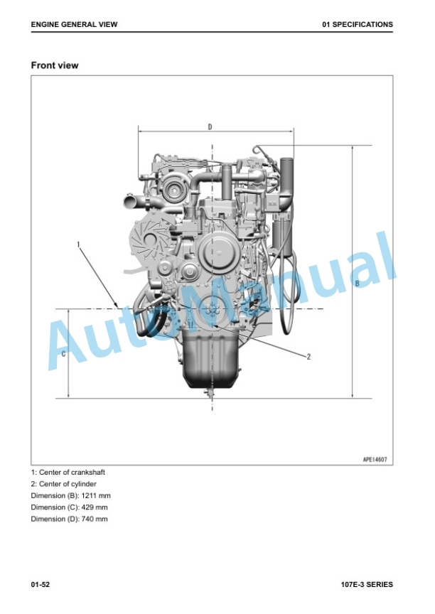
- 1.2.1.3. General view
- 1.2.1.4. Weight table
- 1.2.1.5. Engine performance curves
- 1.3. Structure,function and maintenance standard
- 1.3.1. Structure,function and maintenance standard
- 1.3.1.1. General structure
- 1.3.1.2. Air intake and exhaust system
- 1.3.1.3. Engine unit
- 1.3.1.4. Lubrication system
- 1.3.1.5. Fuel system
- 1.3.1.6. Cooling system
- 1.3.1.7. Electrical equipment
- 1.4. Standard value table
- 1.4.1. Standard value table
- 1.4.1.1. Standard service value table for testing, adjusting, and troubleshooting
- 1.4.1.2. Runningin standard and performance test standard
- 1.5. Testing and adjusting
- 1.5.1. Testing and adjusting
- 1.5.1.1. Testing and adjusting tools list
- 1.5.1.2. Testing exhaust temperature
- 1.5.1.3. Adjusting valve clearance
- 1.5.1.4. Testing compression pressure
- 1.5.1.5. Testing blowby pressure
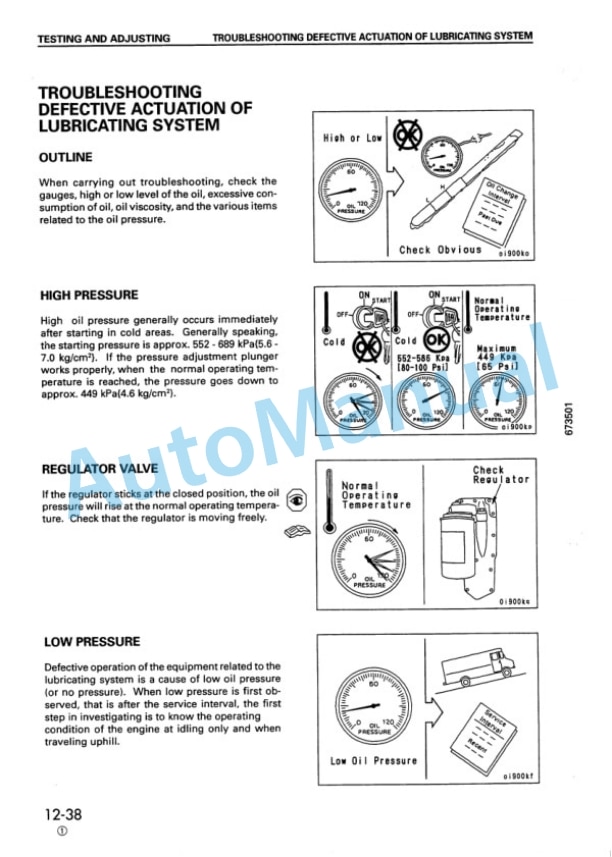
- 1.5.1.6. Testing oil pressure
- 1.5.1.7. Handling fuel system parts
- 1.5.1.8. Releasing residual pressure in fuel system
- 1.5.1.9. Testing fuel pressure
- 1.5.1.10. Reduced cylinder mode operation
- 1.5.1.11. Noinjection cranking
- 1.5.1.12. Testing leakage from pressure limiter and return rate from injector
- 1.5.1.13. Bleeding air from fuel circuit
- 1.5.1.14. Testing fuel system for leakage
- 1.5.1.15. Testing and adjusting alternator belt tension
- 1.5.1.16. Handling controller voltage circuit
- 1.5.1.17. Functions of troubleshooting tool and check of failure code
- 1.6. Troubleshooting
- 1.6.1. Troubleshooting
- 1.6.1.1. General information on troubleshooting
- 1.6.1.2. Troubleshooting for mechanical system (Smode)
- 1.6.1.3. Troubleshooting for electrical system (Emode)
- 1.7. Disassembly and assembly
- 1.7.1. Disassembly and assembly
- 1.7.1.1. How to read this manual
- 1.7.1.2. Coating materials list
- 1.7.1.3. Special tools list
- 1.7.1.4. General disassembly of engine
- 1.7.1.5. General assembly of engine
- 1.7.1.6. Disassembly and assembly procedure for fuel supply pump unit
- 1.7.1.7. Disassembly and assembly procedure for oil seal units
- 1.7.2. OVERALL DRAWING
- 1.7.3. ENGINE PERFORMANCE CURVE
- 1.8. STRUCTURE, FUNCTION AND MAINTENANCE STANDARD
- 1.8.1. GENERAL STRUCTURE
- 1.8.1.1. General structure
- 1.8.2. INTAKE AND EXHAUST SYSTEM
- 1.8.2.1. Intake and exhaust system
- 1.8.2.2. Main revolving system
- 1.8.2.3. Crankshaft
- 1.8.2.4. Piston,piston ring and piston pin
- 1.8.2.5. Connecting rod
- 1.8.2.6. Flywheel and flywheel housing
- 1.8.2.7. Timing gear
- 1.8.2.8. Valve system
- 1.8.2.9. Camshaft
- 1.8.2.10. Rocker arm shaft,push rod and tappet
- 1.8.2.11. Valve,valve guide
- 1.8.3. LUBRICATION SYSTEM
- 1.8.3.1. Lubrication system chart
- 1.8.3.2. Oil pump
- 1.8.3.3. Regulator valve
- 1.8.3.4. Oil filter mount
- 1.8.3.5. Oil filter
- 1.8.4. FUEL SYSTEM
- 1.8.4.1. Fuel system chart
- 1.8.4.2. Fuel injection pump
- 1.8.4.3. Fuel injection nozzle
- 1.8.4.4. Fuel filter
- 1.8.5. COOLING SYSTEM
- 1.8.5.1. Cooling system chart
- 1.8.5.2. Water pump
- 1.8.5.3. Fan drive and thermostat
- 1.8.6. ELECTRICAL SYSTEM
- 1.8.6.1. Starting and charging system electrical circuit diagram
- 1.8.6.2. Alternator
- 1.8.6.3. Starting motor
- 1.8.6.4. Engine starting device
- 1.9. TESTING AND ADJUSTING
- 1.9.1. TESTING AND ADJUSTING
- 1.9.1.1. Adjusting valve clearance
- 1.9.1.2. Measuring compression pressure
- 1.9.1.3. Adjusting fuel injection pressure (Cracking pressure)
- 1.9.1.4. Testing and adjusting fuel injection timing
- 1.9.2. FUEL INJECTION PUMP CALIBRATION DATA
- 1.9.3. PERFORMANCE TEST
- 1.9.3.1. Runin standard
- 1.9.3.2. Performance test criteria
- 1.9.4. TROUBLESHOOTING
- 1.9.4.1. Method of using troubleshooting charts
- 1.9.4.2. Points to remember when troubleshooting
- 1.9.4.3. S 1 Starting performance is poor (starting always takes time)
- 1.9.4.4. S 2 Engine does not start
- 1.9.4.5. S 3 Engine does not pick up smoothly (followup is poor)
- 1.9.4.6. S 4 Engine stops during operations
- 1.9.4.7. S 5 Engine does not rotate smoothly (hunting)
- 1.9.4.8. S 6 Engine lacks output (no power)
- 1.9.4.9. S 7 Exhaust smoke is black (incomplete combustion)
- 1.9.4.10. S 8 Oil consumption is excessive or exhaust smoke is blue
- 1.9.4.11. S 9 Oil becomes contaminated quickly
- 1.9.4.12. S10 Fuel consumption is excessive
- 1.9.4.13. S11 Oil is in coolant, or coolant spurts back,or coolant level goes down
- 1.9.4.14. S12 Oil pressure caution lamp lights up (drop in oil pressure)
- 1.9.4.15. S13 Oil level rises (water,fuel in oil)
- 1.9.4.16. S14 Coolant temperature becomes too high (overheating)
- 1.9.4.17. S15 Abnormal noise is made
- 1.9.4.18. S16 Vibration is excessive
- 1.9.5. TESTING AND ADJUSTING TOOL LIST
- 1.9.6. TESTING AND ADJUSTING DATA
- 1.10. DISASSEMBLY AND ASSEMBLY
- 1.10.1. SPECIAL TOOL LIST
- 1.10.2. OVERALL DISASSEMBLY,ASSEMBLY
- 1.10.3. DISASSEMBLY
- 1.10.4. ASSEMBLY
- 1.11. REPAIR AND REPLACEMENT OF PARTS
- 1.11.1. CYLINDER HEAD SECTION
- 1.11.1.1. Grinding cylinder head mounting surface
- 1.11.1.2. Replacing valve guide
- 1.11.1.3. Grinding valve
- 1.11.2. CYLINDER BLOCK SECTION
- 1.11.2.1. Replacing camshaft bushing
- 1.11.2.2. Replacing crankshaft gear
- 1.11.2.3. Replacing cam gear
- 1.11.2.4. Replacing flywheel ring gear
- 1.11.2.5. Procedure for pressure test
- 1.11.2.6. Cylinder liner (special restoration part)
- 1.11.2.7. Machining drawing for cylinder block bore
- 1.11.2.8. Additional machining of cam journal
- 1.11.2.9. Grinding crankshaft
- 1.11.2.10. Replacing connecting rod small end bushing
- 1.12. BACK COVER
Rate this product
You may also like


- Claas
- Grove
- New Holland
- Komatsu
- Kubota
- John Deere
- Linde
- Bomag
- CASE
- Clark
- JCB
- Jungheinrich
- Linde
- Yale
- Yanmar
- Manitou
- Manitowoc
- CNH
- Doosan
- Fiatagri
- Fiatallis
- Fiatallis Other Manual PDF
- Flexi Coil
- Ford New Holland
- Ford New Holland Other Manual PDF
- Huyndai
- Hypac
- Hyster
- Hyster Service Manual PDF
- Isuzu
- Kobelco
- Kohler
- Krupp
- Lombardini
- Mahindra
- Nuvera
- Perkins
- Sperry New Holland
- Utilev
- Versatile
- ZF