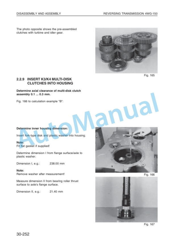
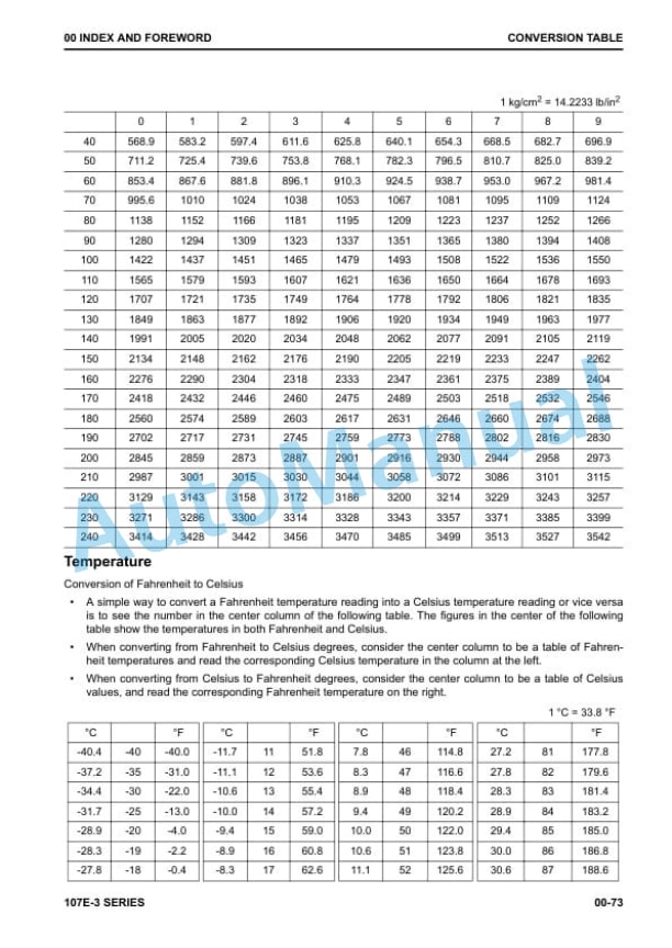
Komatsu WA270-3, WA270PT-3 Wheel Loader Shop Manual VEBM340200
$40.00
- Type Of Manual: Shop Manual
- Manual ID: VEBM340200
- Format: PDF
- Size: 38.6MB
- Number of Pages: 588
Category: Komatsu Shop Manual PDF
-
Model List:
- WA270-3 Wheel Loader
- WA270PT-3 Wheel Loader
- 1. Shop Manual VEBM340200
- 1.1. Contents
- 1.2. Safety notice
- 1.3. Foreword
- 1.4. How to read the shop manual
- 1.5. Hoisting instructions
- 2. General
- 2.1. WA2703 Dimensions, Operating Data
- 2.2. WA270PT3 Dimensions, Operating Data
- 2.3. Specifications
- 2.4. WA2703 Weight Table
- 2.5. WA270PT3 Weight Table
- 2.6. Lubricants and Operating Equipment
- 2.7. Maintenance Schedule
- 2.8. Outlines of Service
- 2.9. Torque List
- 2.10. General View of Controls and Gauges
- 2.11. Emergency Drive
- 3. Structure and Function
- 3.1. Power Train
- 3.2. Power Train System
- 3.3. Torque Converter and Gearbox Piping
- 3.4. Torque Converter
- 3.4.1. Principle of Operation
- 3.5. Powershift Transmission
- 3.5.1. Reversing Transmission 4WG150
- 3.5.1.1. Front View
- 3.5.1.2. Side View
- 3.5.1.3. Rear View
- 3.5.1.4. Electro Hydraulic Control Valve
- 3.5.1.4.1. Detail X
- 3.5.1.5. Inductive Sender
- 3.5.1.6. Proximity Switch
- 3.5.1.7. Pressure Check Points
- 3.5.1.8. Transmission Hydraulic Diagram
- 3.5.1.9. Solenoid Expansion Valve and Overlap Valve
- 3.5.1.10. Thermostat Valve
- 3.5.2. Reversing Transmission 4WG160
- 3.5.2.1. Front View
- 3.5.2.2. Side View
- 3.5.2.3. Rear View
- 3.5.2.4. ElectroHydraulic Shift Control with Proportional Valves
- 3.5.2.5. Measuring Points and Conenctions
- 3.5.2.6. Oil Circuit Diagram Forward 1. Speed
- 3.5.2.7. Inductive Sender
- 3.5.2.8. Proximity Switch
- 3.5.2.9. Thermostat Valve
- 3.6. Drive Shaft
- 3.7. Front and Rear Axles
- 3.8. Differential Unit CK
- 3.9. Differential
- 3.9.1. Limited Slip Differential
- 3.10. Wheel Hub
- 3.11. Axle Mounting
- 3.12. Steering Articulation Joint
- 3.12.1. Outline
- 3.12.2. Assembly
- 3.13. Steering System
- 3.13.1. Steering Column, Orbit Roll
- 3.13.2. Steering Hydraukic Diagram
- 3.13.3. Hydraulic Steering System
- 3.13.3.1. In Neutral
- 3.13.3.2. In Use
- 3.13.4. Steering Servostat Control Valve
- 3.13.4.1. Neutral Position
- 3.13.4.2. Steering Position
- 3.13.5. Steering and Working Hydraulic Pump
- 3.13.6. Steering Orbit Roll
- 3.13.7. Steering Valve Block
- 3.13.8. Steering Damper
- 3.14. Steering Cylinder
- 3.14.1. Steering Cylinder
- 3.15. Emergency Steering Pump
- 3.16. Brake System
- 3.16.1. Brake Valve
- 3.16.1.1. Operating
- 3.16.2. Brake System Circuit
- 3.16.3. Gear Pump
- 3.16.4. Pressure Filter
- 3.16.5. Pressure Regulating Valve
- 3.16.6. Operation
- 3.16.7. Pressure Switch
- 3.16.8. Brake Accumulator
- 3.16.8.1. Hydraulic Circuit
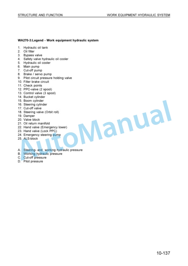
- 3.17. Work Equipment Hydraulic System
- 3.17.1. Pilot Servo System
- 3.17.2. Oil Cooler
- 3.17.3. Combined Cooler
- 3.17.4. Working Hydraulic Pump
- 3.17.5. WA2703 Hydraulic System Diagram
- 3.17.6. WA270PT3 Hydraulic System Diagram
- 3.17.7. WA2703 Cut Off Valve
- 3.17.8. WA270PT3 Pilot Solenoid Valve
- 3.17.9. Main Control Valve
- 3.17.9.1. Shock and Anticavitation Valve
- 3.17.9.2. Anticavitation Valve
- 3.17.10. Pressure Control Valve
- 3.17.11. Joystick, Servo Control Valve
- 3.17.12. Lift Cylinder
- 3.17.13. Tilt Cylinder
- 3.17.14. ALSControl Unit
- 3.17.15. ALS Hydraulic Diagram
- 3.17.16. GasSide Test
- 3.17.17. Topping Up Gas Pressure
- 3.17.18. Hydraulic Accumulator
- 3.18. Lifting Frame
- 3.18.1. WA2703
- 3.18.2. WA270PT3
- 3.19. Bucket Positioner and Boom Kick Out
- 3.19.1. WA2703
- 3.19.2. WA270PT3
- 3.19.2.1. Bucket or Fork Positioner
- 3.19.2.2. Boom Kick Out
- 3.20. Machine Monitor System
- 3.20.1. Main Monitor
- 3.20.1.1. Display Function
- 3.20.1.2. Switch Function
- 3.20.2. Maintenance Monitor
- 3.20.2.1. Display Function
- 3.21. Electrical System
- 3.21.1. PreHeater Plug
- 3.21.2. Fuses
- 3.21.2.1. Slow Blow Fuses
- 3.21.3. Relays
- 3.21.4. Heating and Ventilation System
- 3.21.5. Wiring Diagrams
- 3.22. Air Conditioner
- 3.22.1. In General
- 3.22.2. Characteristics
- 3.22.3. Physical Datas
- 3.22.4. Function
- 3.22.4.1. Coolant Circuit
- 3.22.4.2. Handling Coolants
- 3.22.4.3. Regular Maintenance
- 3.22.4.4. Filling
- 3.22.4.5. Evacuation
- 3.22.4.6. Siphoning Coolant
- 3.22.4.7. Filling Quantity
- 3.22.4.8. Checking Coolant Level
- 3.22.4.9. Compressor Oil Change
- 3.22.4.10. Exchange of Magnetic Clutch
- 3.22.4.11. Exchange of Compressor
- 3.22.4.12. Service Operations
- 3.22.5. Electrical System
- 3.22.5.1. Pin assignment
- 3.22.5.2. Wiring Diagram
- 3.22.6. Technical Data
- 3.22.7. Fault Diagnosis
- 3.22.7.1. Preconditions
- 3.22.7.3. Operating Mode Switch
- 3.22.7.4. Circulating Air Mode
- 3.22.7.5. Temperature Setting
- 3.22.7.6. Air Conditioning Mode
- 3.22.8. Troubleshooting
- 4. Testing and Adjusting
- 4.1. Contents
- 4.1.1. Standard Value Table
- 4.1.2. Test Certificate
- 4.1.2.1. WA2703, current
- 4.1.2.2. WA270PT3, current
- 4.1.2.3. WA2703, new
- 4.1.2.4. WA270PT3, new
- 4.1.3. Engine RPM Load
- 4.1.4. Hydraulic RPM Load
- 4.1.5. Torque Converter And Transmission Pressure
- 4.1.5.1. Current, with 4WG150
- 4.1.5.2. New, with 4WG160
- 4.1.6. Inductive Sender
- 4.1.7. Proximity Switch
- 4.1.8. Operating Force and Travel of Speed Lever
- 4.1.9. Operating Force of Steering Wheel
- 4.1.10. Operating Time for Steering Wheel
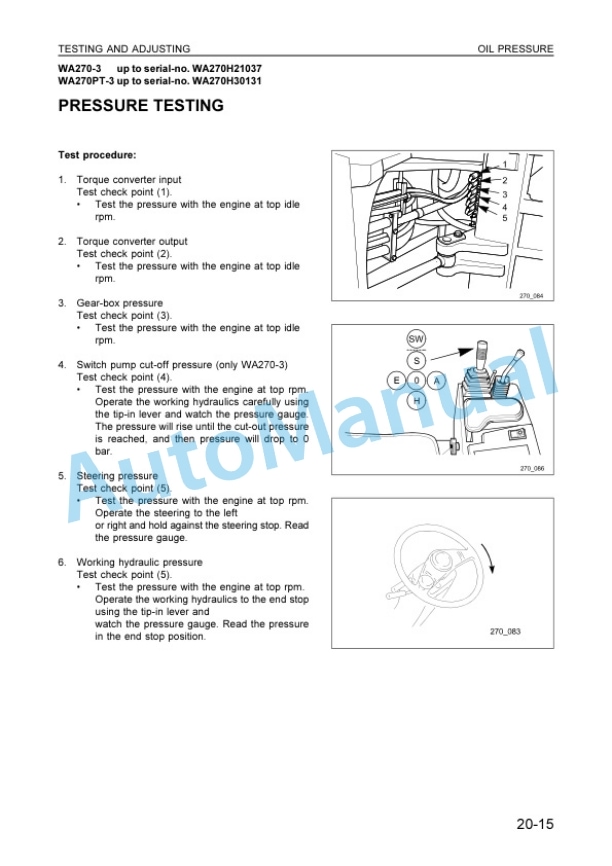
- 4.1.11. Steering Pressure
- 4.1.12. Switch Pump Pressure CutOff
- 4.1.13. Working Hydraulic Pressure
- 4.1.14. Servo Pilot Pressure
- 4.1.15. Hydraulic Drift of Work Equipment
- 4.1.16. Work Equipment
- 4.1.17. Brake Oil Pressure
- 4.1.18. Brake Wear
- 4.1.19. Bleeding of Brake
- 4.1.20. Main Brake Performance
- 4.1.21. Parking Brake Performance
- 4.1.22. Main Monitor
- 4.1.22.1. Speedometer Modul
- 4.1.23. Boom KickOut
- 4.1.24. Accelerator Pedal
- 4.2. Troubleshooting
- 4.2.1. Datas
- 4.2.2. Connecting of AEBStarter and ZFDisplay
- 4.2.3. Operating Instructions AEBStarter
- 4.2.3.1. Introduction
- 4.2.3.2. List of abbreviations
- 4.2.3.3. Procedures to start AEB
- 4.2.3.4. Display
- 4.2.4. Description of fault codes for ERGOControl EST37
- 4.2.4.1. Introduction
- 4.2.4.2. Display during operation
- 4.2.4.3. Display during AEBMode
- 4.2.4.4. Definition of operating modes
- 4.2.4.5. Table of fault codes
- 4.2.4.6. Measuring of resistance at actuator/sensors and cable
- 5. Disassembly and Assembly
- 5.1. Contents
- 5.1.1. Method Of Using Manual
- 5.1.2. Precautions
- 5.1.3. Special Tool List
- 5.1.4. Removal and Install
- 5.1.4.1. Hydraulic Filter
- 5.1.4.2. Steering Cylinder
- 5.1.4.3. Bucket Cylinder
- 5.1.4.4. Boom Cylinder
- 5.1.4.6. Main Monitor
- 5.1.4.7. Maintenance Monitor
- 5.1.4.8. PPCValve
- 5.1.4.9. Main Control Valve
- 5.1.4.10. Steering Valve
- 5.1.4.11. Priority Valve
- 5.1.4.12. Working and Steering Pump
- 5.1.4.13. Drive Shaft
- 5.1.4.14. Front Axle
- 5.1.4.15. Rear Axle
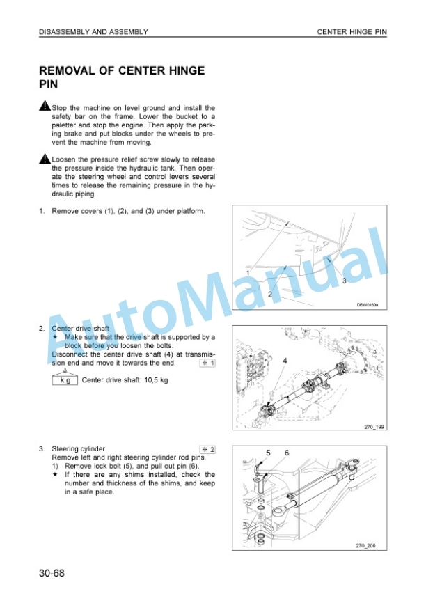
- 5.1.4.16. Center Hinge Pin
- 5.1.4.18. Air Conditioner
- 5.1.4.18.1. Condenser/Dry Receiver
- 5.1.4.18.2. Compressor
- 5.1.5. Disassembly and Assembly
- 5.1.5.1. Axle AP408
- 5.1.5.1.1. Overview
- 5.1.5.1.2. Gear ToothContact
- 5.1.5.1.3. Braking System
- 5.1.5.1.4. Special Tools
- 5.1.5.1.5. Planetary Rigid Axle
- 5.1.5.2. Reversing Transmission 4WG150
- 5.1.5.2.1. Special Tools
- 5.1.5.2.2. ElectroHydraulic Shifting Mechanism
- 5.1.5.2.3. Gear Box
- 5.1.5.3. Reversing Transmission 4WG160
- 5.1.5.3.1. General View
- 5.1.5.3.2. Special Tools
- 5.1.5.3.3. Hydraulic Control Unit
- 5.1.5.3.4. Powershift Transmission
- 6. trouble1.pdf
- 6.1. Connecting of AEBStarter and ZFDisplay
- 6.2. Operating Instructions AEB Starter
- 6.3. KOMATSUP/N 34Y00H0P01
- 6.3.1. Introduction
- 6.3.2. List of abbreviations
- 6.3.2.1. Procedure to start AEB
- 6.3.2.1.2. Display
- 6.4. Introduction
- 6.4.1. Abbreviations
- 6.4.2. ZF Display (42100H0R05)
- 6.4.3. Display during operation
- 6.4.4. Display during AEBMode
- 6.5. Definition of operating modes
Rate this product
You may also like

