- Claas
- Grove
- New Holland
- Komatsu
- Kubota
- John Deere
- Linde
- Bomag
- CASE
- Clark
- JCB
- Jungheinrich
- Linde
- Yale
- Yanmar
- Manitou
- Manitowoc
- CNH
- Doosan
- Fiatagri
- Fiatallis
- Fiatallis Other Manual PDF
- Flexi Coil
- Ford New Holland
- Ford New Holland Other Manual PDF
- Huyndai
- Hypac
- Hyster
- Hyster Service Manual PDF
- Isuzu
- Kobelco
- Kohler
- Krupp
- Lombardini
- Mahindra
- Nuvera
- Perkins
- Sperry New Holland
- Utilev
- Versatile
- ZF


Linde 1166-02 – MR12AP, MR15AP Production site Xiamen Workshop Manuals
$50.00
- Type Of Manual: Workshop Manuals
- Format: PDF
- Size: 35.2MB
- Number of Pages: 278
Category: Linde Workshop Manual PDF
-
Model List:
- MR12AP
- MR15AP Production site Xiamen
- 1. Service case Release tools for contacts
- 1.1. Table of content
- 1.2. Safety information
- 1.2.1. Safety information for repair and maintenance work
- 1.3. Information
- 1.3.1. Information
- 1.4. Overview
- 1.4.1. Overview of service cases
- 1.5. Plug systems
- 1.5.1. ATS 2.8 plug connector
- 1.5.2. CMC plug connector
- 1.5.3. DCS 9.5 plug connector
- 1.5.4. DIN 1.5mm circular connector
- 1.5.5. DIN 2.5mm circular connector
- 1.5.6. Deutsch DTM plug connector
- 1.5.7. ECU appliance plug
- 1.5.8. MCON appliance plug
- 1.5.9. Appliance plug with JPT and MQS contacts
- 1.5.10. Appliance plug with MT2 and JPT contacts
- 1.5.11. SICMA appliance plug
- 1.5.12. Econoseal JMark 2 plug connector
- 1.5.13. Elobau 11pin receptacle housing
- 1.5.14. E5931 plug connector
- 1.5.15. FASTINFASTON 6.3mm plug connector
- 1.5.16. GT150 plug connector
- 1.5.17. HDSCS plug connector
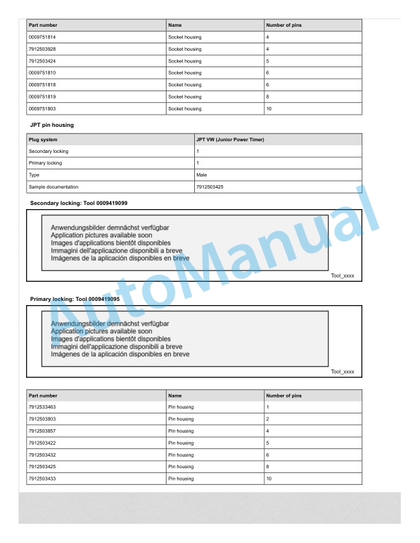
- 1.5.18. JPT plug connector
- 1.5.19. JPT SLD plug connector
- 1.5.20. JPT plug connector Saab
- 1.5.21. JPT plug connector VW
- 1.5.22. Kompakt 1.1 plug connector
- 1.5.23. Bosch Kompakt 4 plug connector
- 1.5.24. Leavyseal plug connector
- 1.5.25. MCON 1.2mm LL plug connector
- 1.5.26. MCON 1.2mm CB plug connector
- 1.5.27. MCP plug connector
- 1.5.28. MetriPack 150 plug connector
- 1.5.29. MiniFit plug connector
- 1.5.30. Mini Universal MATENLOK plug connector
- 1.5.31. Mini relay socket for DFK 1.3 and MDK 1.3
- 1.5.32. MKR Plus plug connector
- 1.5.33. MQS plug connector
- 1.5.34. MR plug connector
- 1.5.35. MTA plug housing and fuse housing
- 1.5.36. MT2 plug connector
- 1.5.37. MT2 1.5mm plug connector VW
- 1.5.38. Multilock plug connector
- 1.5.39. MX150 plug connector
- 1.5.40. NG1 plug connector
- 1.5.41. Phönix Contact HC plug connector
- 1.5.42. PT 3F plug connector
- 1.5.43. Relay socket with SPT contacts for DFK 1.3.4 and MDK 1.3.4
- 1.5.44. Relay socket with SPT and MPT contacts
- 1.5.45. Fuse holder with SPT contacts
- 1.5.46. Sicma plug connector
- 1.5.47. SLK 2.8 plug connector
- 1.5.48. Souriau UTL7 plug connector
- 1.5.49. Superseal 1.5mm plug connector
- 1.5.50. Trident Neptune plug connector
- 1.5.51. Universal MATENLOK plug connector
- 1.5.52. VW 9.5mm plug connector
- 2. Electric Reach TruckMR12AP, MR15AP
- 2.1. Table of content
- 2.2. Product information
- 2.2.1. Overview and specifications
- 2.2.1.1. SAFETY WARNING
- 2.2.1.2. Common Tools
- 2.2.1.3. General Tightening Torques
- 2.2.2. Troubleshooting
- 2.2.2.1. Preparation Before Troubleshooting
- 2.2.2.2. Troubleshooting Solutions of Common Faults
- 2.2.3. App unit item descriptions
- 2.2.3.1. App download guide (China only)
- 2.2.3.2. Backend management
- 2.3. Drive system
- 2.3.1. Drive unit
- 2.3.1.1. Drive System
- 2.3.1.2. Electromagnetic Brakes
- 2.3.1.3. Drive Wheel
- 2.3.1.4. Adjusting the compression spring nut of the suspension mechanism
- 2.3.1.5. Drive Motor
- 2.3.1.6. Gearbox
- 2.3.1.7. Proximity Switch
- 2.3.1.8. Steering Motor
- 2.3.1.9. Speed Encoder
- 2.4. Truck structure
- 2.4.1. Views
- 2.4.1.1. General view
- 2.4.2. Position of main components
- 2.4.2.1. Travel Switch
- 2.4.2.2. Proportional lift lever
- 2.4.2.3. Horn switch
- 2.4.2.4. Emergency reverse switch
- 2.4.2.5. Forward and reverse shift switch
- 2.4.2.6. Tilt switch
- 2.4.2.7. Emergency Stop Switch
- 2.4.2.8. Key Switch . Charge Gauge
- 2.4.2.9. Traction Controller.Fuse
- 2.4.2.10. Horn
- 2.4.2.11. Main Contactor
- 2.4.2.12. EPSDC0 Controller
- 2.4.2.13. Lifting Limit Switch
- 2.4.2.14. Interlock Switch
- 2.4.2.15. MotorPump
- 2.4.2.16. Potentiometer
- 2.4.2.17. Multiway Solenoid Valve
- 2.4.3. Chassis components
- 2.4.3.1. Removal and Installation
- 2.4.3.2. Removal and Installation
- 2.4.4. Chassis lubrication
- 2.4.4.1. Application Amount of Hydraulic Oil
- 2.4.4.2. Sliding Surface
- 2.5. Steering and wheels
- 2.5.1. Load wheels
- 2.5.1.1. Removal and Installation
- 2.5.1.2. Load Wheels Faults and Causes
- 2.5.2. Castors
- 2.5.2.1. View
- 2.5.2.2. Caster removal and installation
- 2.6. Operating device
- 2.6.1. Operating handle
- 2.6.1.1. Removing and installing the operating handle
- 2.6.1.2. Removing the operating handle
- 2.6.2. Button switch and lever
- 2.6.2.1. Faults and Causes
- 2.6.3. Twoway potentiometer
- 2.6.3.1. Removal and Installation
- 2.6.3.2. Faults and Causes
- 2.6.3.3. Checking and Testing
- 2.6.3.4. Control Circuit Troubleshooting
- 2.7. Electrical system
- 2.7.1. Control unit
- 2.7.1.1. Control unit interface function
- 2.7.1.2. Controller Functions
- 2.7.2. Electrical components
- 2.7.2.1. Fuse
- 2.7.2.2. Key Switch
- 2.7.2.3. Main Contactor
- 2.7.2.4. Lifting Limit Switch
- 2.7.2.5. Sidegate Switch
- 2.7.2.6. Cooling Fan
- 2.7.2.7. Deadman Switch
- 2.7.2.8. Proximity Switch
- 2.7.2.9. Interlock Switch
- 2.7.2.10. Charge Gauge
- 2.7.3. Handheld diagnostic instrument
- 2.7.3.1. Fault Detection
- 2.7.3.2. Testing Truck Operation
- 2.7.3.3. Set Options
- 2.7.3.4. Instruction of Set Options
- 2.7.3.5. Adjustments
- 2.7.3.6. Instruction of Adjustments
- 2.7.3.7. Parameter Change
- 2.7.3.8. Instruction of Parameter Change
- 2.7.3.9. Controller Error Message
- 2.7.3.10. ZAPI Controller Error Codes_ACE0
- 2.7.3.11. Traction.Pump Controller
- 2.7.3.12. Steering Controller (EPSACO) Error codes
- 2.8. Hydraulic system
- 2.8.1. Overview
- 2.8.1.1. Hydraulic Overview
- 2.8.1.2. Hydraulic Troubleshooting
- 2.8.1.3. Pump and Motor Assembly
- 2.8.2. Hydraulic components
- 2.8.2.1. Pump Motor
- 2.8.2.2. Multiway Reversing Solenoid Valve
- 2.8.2.3. Solenoid Valve
- 2.8.2.4. Gear Pump
- 2.8.2.5. Reach Cylinder
- 2.9. Lift mast
- 2.9.1. Duplex mast
- 2.9.1.1. Twostage Mast Removal and Installation
- 2.9.1.2. Tilt Cylinde
- 2.9.1.3. Lift Cylinder
- 2.9.1.4. Lifting Chains
- 2.9.1.5. Mast Tubing
- 2.9.2. Triplex mast
- 2.9.2.1. Lift Cylinder
- 2.9.2.2. Lifting Chains
- 2.9.2.3. Mast Removal and Installation
- 2.9.2.4. Mast Tubing
- 2.10. Special equipment
- 2.10.1. Leadacid battery
- 2.10.1.1. Maintenance and Care
- 2.10.1.2. Use of Battery
- 2.10.1.3. Storage
- 2.10.1.4. Troubleshooting
- 2.10.1.5. Safety and Warnings
- 2.10.2. Maintenancefree battery
- 2.10.2.1. Safety and Warnings
- 2.11. Schematic diagrams
- 2.11.1. Electrical diagrams
- 2.11.1.1. Electrical diagrams
- 2.11.2. Hydraulics diagrams
- 2.11.2.1. Hydraulic diagram
Rate this product
You may also like

Linde Workshop Manual PDF
Linde 1110-01 – N20C, N20VI, N20VLI, V08-01, V08-02 Workshop Manuals SN W41110V00529 and up
$50.00

Linde Workshop Manual PDF
Linde 1110-01 – V08-01, V08-02 Workshop Manuals SN 11.09 and up SN up to W41110V00528
$50.00


Linde Workshop Manual PDF
Linde 1102-02 – ECR30, ECR40 Production site LMH-NA Workshop Manuals SN A11102V00001 and up
$50.00


- Claas
- Grove
- New Holland
- Komatsu
- Kubota
- John Deere
- Linde
- Bomag
- CASE
- Clark
- JCB
- Jungheinrich
- Linde
- Yale
- Yanmar
- Manitou
- Manitowoc
- CNH
- Doosan
- Fiatagri
- Fiatallis
- Fiatallis Other Manual PDF
- Flexi Coil
- Ford New Holland
- Ford New Holland Other Manual PDF
- Huyndai
- Hypac
- Hyster
- Hyster Service Manual PDF
- Isuzu
- Kobelco
- Kohler
- Krupp
- Lombardini
- Mahindra
- Nuvera
- Perkins
- Sperry New Holland
- Utilev
- Versatile
- ZF