- Claas
- Grove
- New Holland
- Komatsu
- Kubota
- John Deere
- Linde
- Bomag
- CASE
- Clark
- JCB
- Jungheinrich
- Linde
- Yale
- Yanmar
- Manitou
- Manitowoc
- CNH
- Doosan
- Fiatagri
- Fiatallis
- Fiatallis Other Manual PDF
- Flexi Coil
- Ford New Holland
- Ford New Holland Other Manual PDF
- Huyndai
- Hypac
- Hyster
- Hyster Service Manual PDF
- Isuzu
- Kobelco
- Kohler
- Krupp
- Lombardini
- Mahindra
- Nuvera
- Perkins
- Sperry New Holland
- Utilev
- Versatile
- ZF


Linde 1167-02 – ML10, ML12, MM10, MM12, MM12i Production site Xiamen Workshop Manuals SN CT1167H20001 and up
$50.00
- Type Of Manual: Workshop Manuals
- Manual ID: SN CT1167H20001 and up
- Format: PDF
- Size: 37.7MB
- Number of Pages: 285
- Serial Number:
SN CT1167H20001 and up
Category: Linde Workshop Manual PDF
-
Model List:
- ML10
- ML12
- MM10
- MM12
- MM12i
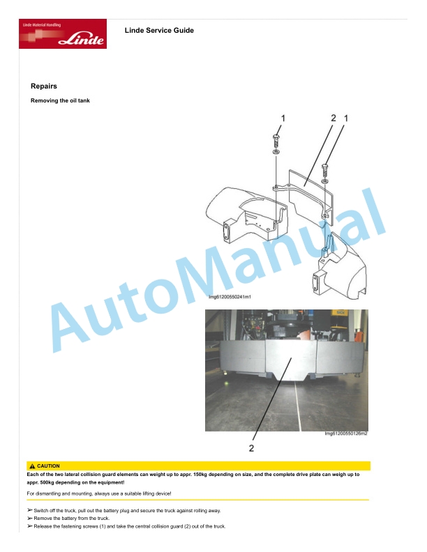
- 1. Service case Release tools for contacts
- 1.1. Table of content
- 1.2. Safety information
- 1.2.1. Safety information for repair and maintenance work
- 1.3. Information
- 1.3.1. Information
- 1.4. Overview
- 1.4.1. Overview of service cases
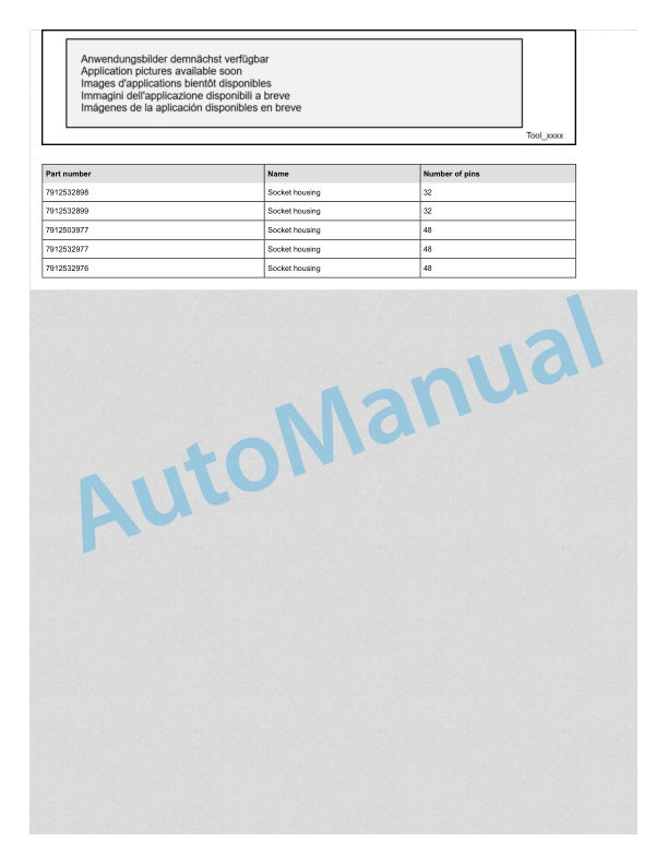
- 1.5. Plug systems
- 1.5.1. ATS 2.8 plug connector
- 1.5.2. CMC plug connector
- 1.5.3. DCS 9.5 plug connector
- 1.5.4. DIN 1.5mm circular connector
- 1.5.5. DIN 2.5mm circular connector
- 1.5.6. Deutsch DTM plug connector
- 1.5.7. ECU appliance plug
- 1.5.8. MCON appliance plug
- 1.5.9. Appliance plug with JPT and MQS contacts
- 1.5.10. Appliance plug with MT2 and JPT contacts
- 1.5.11. SICMA appliance plug
- 1.5.12. Econoseal JMark 2 plug connector
- 1.5.13. Elobau 11pin receptacle housing
- 1.5.14. E5931 plug connector
- 1.5.15. FASTINFASTON 6.3mm plug connector
- 1.5.16. GT150 plug connector
- 1.5.17. HDSCS plug connector
- 1.5.18. JPT plug connector
- 1.5.19. JPT SLD plug connector
- 1.5.20. JPT plug connector Saab
- 1.5.21. JPT plug connector VW
- 1.5.22. Kompakt 1.1 plug connector
- 1.5.23. Bosch Kompakt 4 plug connector
- 1.5.24. Leavyseal plug connector
- 1.5.25. MCON 1.2mm LL plug connector
- 1.5.26. MCON 1.2mm CB plug connector
- 1.5.27. MCP plug connector
- 1.5.28. MetriPack 150 plug connector
- 1.5.29. MiniFit plug connector
- 1.5.30. Mini Universal MATENLOK plug connector
- 1.5.31. Mini relay socket for DFK 1.3 and MDK 1.3
- 1.5.32. MKR Plus plug connector
- 1.5.33. MQS plug connector
- 1.5.34. MR plug connector
- 1.5.35. MTA plug housing and fuse housing
- 1.5.36. MT2 plug connector
- 1.5.37. MT2 1.5mm plug connector VW
- 1.5.38. Multilock plug connector
- 1.5.39. MX150 plug connector
- 1.5.40. NG1 plug connector
- 1.5.41. Phönix Contact HC plug connector
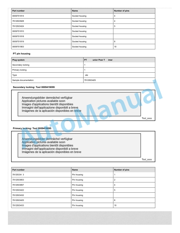
- 1.5.42. PT 3F plug connector
- 1.5.43. Relay socket with SPT contacts for DFK 1.3.4 and MDK 1.3.4
- 1.5.44. Relay socket with SPT and MPT contacts
- 1.5.45. Fuse holder with SPT contacts
- 1.5.46. Sicma plug connector
- 1.5.47. SLK 2.8 plug connector
- 1.5.48. Souriau UTL7 plug connector
- 1.5.49. Superseal 1.5mm plug connector
- 1.5.50. Trident Neptune plug connector
- 1.5.51. Universal MATENLOK plug connector
- 1.5.52. VW 9.5mm plug connector
- 2. Electric Pallet StackerML10 . ML12MM10 . MM10i . MM12
- 2.1. Table of content
- 2.2. Product information
- 2.2.1. Overview and specifications
- 2.2.1.1. SAFETY WARNING
- 2.2.1.2. Common Tools
- 2.2.1.3. General Tightening Torques
- 2.2.2. Troubleshooting
- 2.2.2.1. Preparation Before Troubleshooting
- 2.2.2.2. Troubleshooting Solutions of Common Faults
- 2.2.3. Test specification
- 2.2.3.1. Insulation test of the truck
- 2.2.3.2. Insulation test of the battery
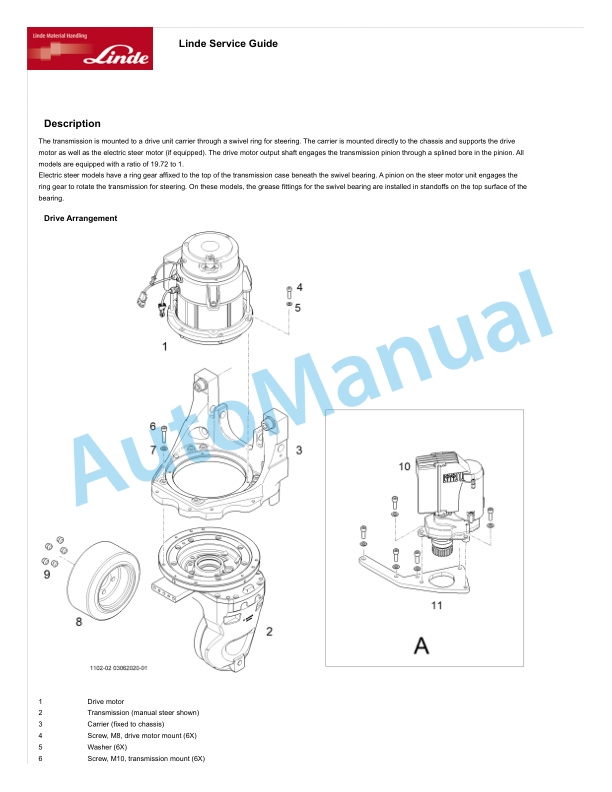
- 2.3. Drive system
- 2.3.1. Drive unit
- 2.3.1.1. Drive System
- 2.3.1.2. Removal and Installation
- 2.3.1.3. Electromagnetic Brakes
- 2.3.1.4. Drive Wheel
- 2.3.1.5. Drive Motor
- 2.3.1.6. Gearbox
- 2.4. Truck structure
- 2.4.1. Views
- 2.4.1.1. Main Components(old CE)
- 2.4.1.2. Main Components (new CE)
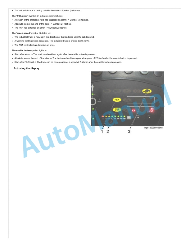
- 2.4.1.3. Display instrument
- 2.4.1.4. How to distinguish old CE truck and new CE truck
- 2.4.2. Position of main components
- 2.4.2.1. Old CE
- 2.4.2.1.1. Travel Switch
- 2.4.2.1.2. Lifting.Lowering Switch
- 2.4.2.1.3. Emergency Reverse Switch
- 2.4.2.1.4. Horn Switch
- 2.4.2.1.5. Fuse
- 2.4.2.1.6. Controller
- 2.4.2.2. New CE
- 2.4.2.2.1. Drive switch
- 2.4.2.2.2. Lifting.lowering switch
- 2.4.2.2.3. Emergency reverse switch
- 2.4.2.2.4. Horn switch
- 2.4.2.2.5. Fuses
- 2.4.2.2.6. Control unit
- 2.4.2.3. Key switch
- 2.4.2.4. Emergency off switch
- 2.4.2.5. Horn
- 2.4.2.6. Battery charger
- 2.4.2.7. Charge Gauge
- 2.4.2.8. Charging indicator light
- 2.4.2.9. Lifting Limit Switch
- 2.4.2.10. Interlock Switch
- 2.4.2.11. Pump Motor
- 2.4.2.12. Gear Pump
- 2.4.2.13. Pump Contactor
- 2.4.2.14. Solenoid Valve
- 2.4.3. Cowling
- 2.4.3.1. Cover Removal and Installation
- 2.5. Steering and wheels
- 2.5.1. Load wheels
- 2.5.1.1. Load Wheels Removal and Installation
- 2.5.1.2. Load Wheels Faults and Causes
- 2.5.2. Castors
- 2.5.2.1. Caster Removal and Installation
- 2.6. Operating device
- 2.6.1. Operating handle
- 2.6.1.1. Old CE
- 2.6.1.1.1. Control Lever
- 2.6.1.1.2. Button Switch
- 2.6.1.1.3. Travel Switch
- 2.6.1.2. New CE
- 2.6.1.2.1. Driving tiller
- 2.6.1.2.2. Removing the tiller end section
- 2.6.1.2.3. Malfunctions and causes
- 2.7. Electrical equipment
- 2.7.1. Control unit (old CE)
- 2.7.1.1. Controller Removal and Installation
- 2.7.1.2. Controller Interface Function (Old)
- 2.7.1.3. Controller Interface Function (New)
- 2.7.2. Handheld diagnostic instrument (Old CE)
- 2.7.2.1. Handheld unit (optional)
- 2.7.2.2. Parameter Settings
- 2.7.2.3. Monitor Menu
- 2.7.2.4. Control unit error codes
- 2.7.3. Control unit (new CE)
- 2.7.3.1. Control unit Removing and Installing
- 2.7.3.2. Control Unit Interface Features (New CE)
- 2.7.4. Handheld diagnostic instrument (New CE)
- 2.7.4.1. Connecting the handheld unit
- 2.7.4.2. Handheld Unit (Optional)
- 2.7.4.3. Controller Error Message
- 2.7.5. Electrical components
- 2.7.5.1. Fuses
- 2.7.5.2. Key Switch
- 2.7.5.3. Charge Gauge (Old)
- 2.7.5.4. Power gauge (new)
- 2.7.5.5. LED charging indicator light
- 2.7.5.6. Stroke switch
- 2.7.5.7. Interlock Switch
- 2.7.6. Maintenancefree battery
- 2.7.6.1. Maintenancefree Battery Safety and Warnings
- 2.7.6.2. Use of Battery
- 2.7.6.3. Battery Maintenance and Care
- 2.8. Hydraulic system
- 2.8.1. Overview
- 2.8.1.1. Hydraulic system overview
- 2.8.1.2. Hydraulic station
- 2.8.1.3. Hydraulic Troubleshooting
- 2.8.2. Hydraulic components
- 2.8.2.1. Pump Motor
- 2.8.2.2. Pump Contactor
- 2.8.2.3. Solenoid Valve
- 2.8.2.4. Cylinder
- 2.9. Lift mast
- 2.9.1. Simplex mast
- 2.9.1.1. Lifting Chain
- 2.9.1.2. Lift Cylinder
- 2.9.2. Duplex mast
- 2.9.2.1. Lifting Chains
- 2.9.2.2. Lifting Cylinder
- 2.10. Schematic diagrams
- 2.10.1. Diagram EN1175 (new CE) starting from June 2023
- 2.10.1.1. Electrical diagrams
- 2.10.1.1.1. Electric diagram (without initial lift)
- 2.10.1.1.2. Electric diagram (with initial lift)
- 2.10.1.1.3. Main harness diagram (without initial lift)
- 2.10.1.1.4. Main harness diagram (with initial lift)
- 2.10.1.1.5. Tiller harness diagram (with initial lift)
- 2.10.1.2. Hydraulics diagrams
- 2.10.1.2.1. Hydraulic diagram(new CE)
- 2.10.1.3. Brake schematic diagrams
- 2.10.1.3.1. Brake Principle
- 2.10.2. Diagrams starting from September 2018
- 2.10.2.1. Electrical diagrams
- 2.10.2.1.1. Electrical diagrams (with initial lift)
- 2.10.2.1.2. Electrical diagrams (without initial lift)
- 2.10.2.2. Hydraulics diagrams
- 2.10.2.2.1. Hydraulic Diagram
- 2.10.2.3. Brake schematic diagrams
- 2.10.2.3.1. Brake Principle
- 2.10.3. Diagrams starting from May 2018
- 2.10.3.1. Electrical diagrams
- 2.10.3.1.1. Wire Diagram (with initial lift)
- 2.10.3.1.2. Wire Diagram (without initial lift)
- 2.10.3.2. Hydraulics diagrams
- 2.10.3.2.1. Hydraulic Diagram
- 2.10.3.3. Brake schematic diagrams
- 2.10.3.3.1. Brake Principle
- 2.10.4. Electrical diagrams till April 2018
- 2.10.4.1. Electrical diagrams
- 2.10.4.1.1. Electric diagram (without initial lift)
- 2.10.4.1.2. Cable wiring diagram
- 2.10.4.1.3. Electrical diagram with initial lift nonCAN
- 2.10.4.1.4. Harness Diagram
- 2.10.4.2. Hydraulics diagrams
- 2.10.4.2.1. Hydraulic Diagram
- 2.10.4.3. Brake schematic diagrams
- 2.10.4.3.1. Brake Principle
Rate this product
You may also like

Linde Workshop Manual PDF
Linde 011-01 – K Generation 1 2, K Generation 3, K Generation 4 Workshop Manuals
$50.00

Linde Workshop Manual PDF
$50.00


Linde Workshop Manual PDF
Linde 1103-02 – ETR50 Production site LMH-NA Workshop Manuals SN A11103V00001 and up
$50.00


- Claas
- Grove
- New Holland
- Komatsu
- Kubota
- John Deere
- Linde
- Bomag
- CASE
- Clark
- JCB
- Jungheinrich
- Linde
- Yale
- Yanmar
- Manitou
- Manitowoc
- CNH
- Doosan
- Fiatagri
- Fiatallis
- Fiatallis Other Manual PDF
- Flexi Coil
- Ford New Holland
- Ford New Holland Other Manual PDF
- Huyndai
- Hypac
- Hyster
- Hyster Service Manual PDF
- Isuzu
- Kobelco
- Kohler
- Krupp
- Lombardini
- Mahindra
- Nuvera
- Perkins
- Sperry New Holland
- Utilev
- Versatile
- ZF