- Claas
- Grove
- New Holland
- Komatsu
- Kubota
- John Deere
- Linde
- Bomag
- CASE
- Clark
- JCB
- Jungheinrich
- Linde
- Yale
- Yanmar
- Manitou
- Manitowoc
- CNH
- Doosan
- Fiatagri
- Fiatallis
- Fiatallis Other Manual PDF
- Flexi Coil
- Ford New Holland
- Ford New Holland Other Manual PDF
- Huyndai
- Hypac
- Hyster
- Hyster Service Manual PDF
- Isuzu
- Kobelco
- Kohler
- Krupp
- Lombardini
- Mahindra
- Nuvera
- Perkins
- Sperry New Holland
- Utilev
- Versatile
- ZF


Linde 1287-01 – E40 to E50B Production site China, LX Workshop Manuals SN C11287X00009 and up
$50.00
- Type Of Manual: Workshop Manuals
- Manual ID: SN C11287X00009 and up
- Format: PDF
- Size: 43.9MB
- Number of Pages: 373
- Serial Number:
SN C11287X00009 and up
Category: Linde Workshop Manual PDF
-
Model List:
- E40
- E40-20
- E40B
- E45
- E45-20
- E45B
- E50
- E50-20
- E50B
- 1. Service case Release tools for contacts
- 1.1. Table of content
- 1.2. Safety information
- 1.2.1. Safety information for repair and maintenance work
- 1.3. Information
- 1.3.1. Information
- 1.4. Overview
- 1.4.1. Overview of service cases
- 1.5. Plug systems
- 1.5.1. ATS 2.8 plug connector
- 1.5.2. CMC plug connector
- 1.5.3. DCS 9.5 plug connector
- 1.5.4. DIN 1.5mm circular connector
- 1.5.5. DIN 2.5mm circular connector
- 1.5.6. Deutsch DTM plug connector
- 1.5.7. ECU appliance plug
- 1.5.8. MCON appliance plug
- 1.5.9. Appliance plug with JPT and MQS contacts
- 1.5.10. Appliance plug with MT2 and JPT contacts
- 1.5.11. SICMA appliance plug
- 1.5.12. Econoseal JMark 2 plug connector
- 1.5.13. Elobau 11pin receptacle housing
- 1.5.14. E5931 plug connector
- 1.5.15. FASTINFASTON 6.3mm plug connector
- 1.5.16. GT150 plug connector
- 1.5.17. HDSCS plug connector
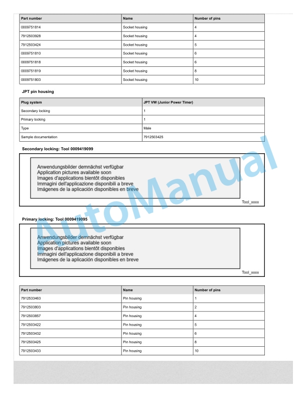
- 1.5.18. JPT plug connector
- 1.5.19. JPT SLD plug connector
- 1.5.20. JPT plug connector Saab
- 1.5.21. JPT plug connector VW
- 1.5.22. Kompakt 1.1 plug connector
- 1.5.23. Bosch Kompakt 4 plug connector
- 1.5.24. Leavyseal plug connector
- 1.5.25. MCON 1.2mm LL plug connector
- 1.5.26. MCON 1.2mm CB plug connector
- 1.5.27. MCP plug connector
- 1.5.28. MetriPack 150 plug connector
- 1.5.29. MiniFit plug connector
- 1.5.30. Mini Universal MATENLOK plug connector
- 1.5.31. Mini relay socket for DFK 1.3 and MDK 1.3
- 1.5.32. MKR Plus plug connector
- 1.5.33. MQS plug connector
- 1.5.34. MR plug connector
- 1.5.35. MTA plug housing and fuse housing
- 1.5.36. MT2 plug connector
- 1.5.37. MT2 1.5mm plug connector VW
- 1.5.38. Multilock plug connector
- 1.5.39. MX150 plug connector
- 1.5.40. NG1 plug connector
- 1.5.41. Phönix Contact HC plug connector
- 1.5.42. PT 3F plug connector
- 1.5.43. Relay socket with SPT contacts for DFK 1.3.4 and MDK 1.3.4
- 1.5.44. Relay socket with SPT and MPT contacts
- 1.5.45. Fuse holder with SPT contacts
- 1.5.46. Sicma plug connector
- 1.5.47. SLK 2.8 plug connector
- 1.5.48. Souriau UTL7 plug connector
- 1.5.49. Superseal 1.5mm plug connector
- 1.5.50. Trident Neptune plug connector
- 1.5.51. Universal MATENLOK plug connector
- 1.5.52. VW 9.5mm plug connector
- 2. Electric forklift truckE40, E45, E50,E40B, E45B, E50B
- 2.1. Table of content
- 2.2. Product information
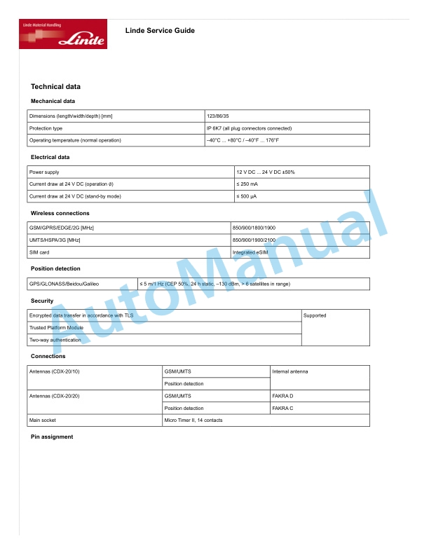
- 2.2.1. Technical data
- 2.2.1.1. Truck serial number
- 2.2.1.2. Tightening torque requirements for standard bolts
- 2.2.1.3. _Tightening torque requirements for some bolts
- 2.2.2. Diagnostic software
- 2.2.2.1. Calibrating an acceleration potentiometer
- 2.2.2.2. Calibrating the handle
- 2.2.2.3. Steering angle sensor calibration
- 2.2.2.4. Electronic parking brake eFSB calibration
- 2.2.2.5. Setting eFSB parameters
- 2.2.3. CAN box
- 2.2.3.1. Authorisations
- 2.2.3.2. CAN box
- 2.2.3.3. USBCANBox 2 and BluetoothCANBox 3 software update
- 2.2.4. Error code
- 2.2.4.1. Code lists
- 2.2.4.2. Traction
- 2.2.4.3. Working hydraulics
- 2.2.4.4. Single Power unit _ working hydraulic
- 2.2.4.5. Double Power unit _ traction left traction right
- 2.2.4.6. Display unit error codes
- 2.2.5. Aftersales service
- 2.2.5.1. Inspection and maintenance data
- 2.2.5.2. Recommended fuels and oils
- 2.2.5.3. Service plan table
- 2.3. Drive mechanism and transmission system
- 2.3.1. Drive axle
- 2.3.1.1. Overview of drive axle
- 2.3.1.2. Drive axle sensor
- 2.3.1.3. Drive axle filling oil inlet overview
- 2.3.2. Drive axle speed reduction gearbox
- 2.3.2.1. Checking the oil level of the reduction gearbox
- 2.3.2.2. Changing the reduction gearbox oil
- 2.3.3. Drive motor
- 2.3.3.1. Motor terminals
- 2.3.4. Sensors
- 2.3.4.1. Drive axle temperature sensor
- 2.3.5. Brake system
- 2.3.5.1. Manually releasing the electronic parking brake
- 2.3.5.2. Electronic parking brake
- 2.3.5.3. The electronic parking eFSB brake system
- 2.3.5.4. Checking the brake fluid level in the brake fluid reservoir
- 2.3.5.5. Replacing the oil in the brake fluid reservoir
- 2.3.6. Steering system
- 2.3.6.1. Functional description
- 2.3.6.2. Steering column assembly
- 2.3.6.3. Steering system overview
- 2.3.7. Steering axle
- 2.3.7.1. Functional description
- 2.3.7.2. Removing the steering axle
- 2.3.7.3. Changing the steering cylinder seals
- 2.3.7.4. Adjusting the steering lock
- 2.3.7.5. Steering angle sensor 3B1
- 2.3.7.6. Changing the steering angle sensor
- 2.4. Chassis and bodywork
- 2.4.1. Chassis design
- 2.4.1.1. Chassis design
- 2.5. Drivers cab
- 2.5.1. Drivers handhold
- 2.5.1.1. Handhold
- 2.5.2. Drivers seat
- 2.5.2.1. Seat belt monitoring and alarm function
- 2.5.2.2. Seat belt monitoring and alarm
- 2.5.3. Operating handle
- 2.5.3.1. Joystick variants
- 2.5.3.2. Joystick interlock
- 2.5.3.3. Exchange
- 2.6. Electrics.electronics
- 2.6.1. Overview
- 2.6.1.1. Electrical equipment safety instructions
- 2.6.1.2. Cleaning the electrical system
- 2.6.1.3. Insulation test
- 2.6.1.4. EMC Electromagnetic compatibility
- 2.6.1.5. CAN bus
- 2.6.1.6. Electrostatic charging
- 2.6.1.7. Power module and motor layout
- 2.6.1.8. Layout of electric components
- 2.6.2. Electrical components
- 2.6.2.1. Emergency stop switch
- 2.6.2.2. Main contactor
- 2.6.2.3. Fan control
- 2.6.2.4. Current sensor version 2
- 2.6.2.5. Operating lever controls
- 2.6.2.6. Horn
- 2.6.3. Power module
- 2.6.3.1. Overview of functional modules
- 2.6.3.2. Power module pins
- 2.6.4. Control module
- 2.6.4.1. Truck control unit overview
- 2.6.4.2. Pin assignments for truck control unit
- 2.6.4.3. Truck control unit pin assignment
- 2.6.5. Display unit
- 2.6.5.1. Display unit
- 2.6.5.2. Display unit overview
- 2.6.5.3. Original pin definition
- 2.7. Hydraulic system
- 2.7.1. Overview
- 2.7.1.1. Hydraulic system contamination
- 2.7.2. Basic hydraulics
- 2.7.2.1. Gear pump
- 2.7.2.2. Priority valve
- 2.7.2.3. Steering control valve
- 2.7.2.4. Control valve
- 2.7.2.5. Filter and oil tank accessories
- 2.7.2.6. Tilt cylinder
- 2.7.2.7. Changing the hydraulic oil
- 2.7.2.8. Replacing the filter
- 2.8. Lifting system
- 2.8.1. Lift mast
- 2.8.1.1. Safety information for lift mast operations
- 2.8.1.2. Lift mast chains
- 2.8.1.3. Adjusting the lift mast chain
- 2.8.1.4. Rupture valve
- 2.8.1.5. Adjusting the tilt angle of the mast
- 2.9. Special equipment
- 2.9.1. Battery
- 2.9.1.1. Lead acid battery introduction
- 2.9.2. Other devices
- 2.9.2.1. Electrostatic belt
- 3. Maintenance of charger ADY 6117
- 4. Schematic diagramsBattery Counterbalanced Forklift TruckE40, E45, E50E4020, E4520, E5020
- 4.1. Table of content
- 4.2. Electrical diagrams
- 4.2.1. Electrical diagrams_E40.45.50
- 4.2.1.1. Electrical diagrams15.9.2021 after 30.6.2022
- 4.2.1.1.1. Electrical diagram_1
- 4.2.1.1.2. Electrical diagram_2
- 4.2.1.1.3. Electrical diagram_3
- 4.2.1.1.4. Electrical diagram_4
- 4.2.1.1.5. Electrical diagram_5
- 4.2.1.1.6. Electrical diagram_6
- 4.2.1.1.7. Electrical diagram_7
- 4.2.1.2. Electrical diagram 14.9.2021
- 4.2.1.2.1. Electrical diagram_1
- 4.2.1.2.2. Electrical diagram_5
- 4.2.2. Electrical diagrams_E40.45.5020
- 4.2.2.1. Electrical diagrams 30.6.2022
- 4.2.2.1.1. Electrical diagrams_1
- 4.2.2.1.2. Electrical diagrams_2
- 4.2.2.1.3. Electrical diagrams_3
- 4.2.2.1.4. Electrical diagrams_4
- 4.2.2.1.5. Electrical diagrams_5
- 4.2.2.1.6. Electrical diagrams_6
- 4.2.2.1.7. Electrical diagrams_7
- 4.2.3. Electrical diagrams_work lights, fully enclosed cab option
- 4.2.3.1. Electrical diagram_1
- 4.2.3.2. Electrical diagram_2
- 4.3. Hydraulics diagrams
- 4.3.1. Hydraulics diagrams
- 4.3.2. Hydraulic pressure diagrams_E40.45.5020
- 4.4. Brake schematic diagrams
- 4.4.1. Brake schematic diagram
- 4.5. Diagram of major stressed structural parts
- 4.5.1. Diagram of major stressed structural parts
Rate this product
You may also like

Linde Workshop Manual PDF
Linde 1102-02 – ECR30, ECR40 Production site LMH-NA Workshop Manuals SN A11102V00001 and up
$50.00

Linde Workshop Manual PDF
Linde 1110-01 – V08-01, V08-02 Workshop Manuals SN 11.09 and up SN up to W41110V00528
$50.00

Linde Workshop Manual PDF
$50.00


Linde Workshop Manual PDF
Linde 1102-01 – ECR27, ECR36 Production site LMH-NA Workshop Manuals
$50.00


Linde Workshop Manual PDF
Linde 1101-01 – EW27, EW36, EWR27, EWR36 Production site LMH-NA Workshop Manuals
$50.00
- Claas
- Grove
- New Holland
- Komatsu
- Kubota
- John Deere
- Linde
- Bomag
- CASE
- Clark
- JCB
- Jungheinrich
- Linde
- Yale
- Yanmar
- Manitou
- Manitowoc
- CNH
- Doosan
- Fiatagri
- Fiatallis
- Fiatallis Other Manual PDF
- Flexi Coil
- Ford New Holland
- Ford New Holland Other Manual PDF
- Huyndai
- Hypac
- Hyster
- Hyster Service Manual PDF
- Isuzu
- Kobelco
- Kohler
- Krupp
- Lombardini
- Mahindra
- Nuvera
- Perkins
- Sperry New Holland
- Utilev
- Versatile
- ZF