- Claas
- Grove
- New Holland
- Komatsu
- Kubota
- John Deere
- Linde
- Bomag
- CASE
- Clark
- JCB
- Jungheinrich
- Linde
- Yale
- Yanmar
- Manitou
- Manitowoc
- CNH
- Doosan
- Fiatagri
- Fiatallis
- Fiatallis Other Manual PDF
- Flexi Coil
- Ford New Holland
- Ford New Holland Other Manual PDF
- Huyndai
- Hypac
- Hyster
- Hyster Service Manual PDF
- Isuzu
- Kobelco
- Kohler
- Krupp
- Lombardini
- Mahindra
- Nuvera
- Perkins
- Sperry New Holland
- Utilev
- Versatile
- ZF


Linde 1346-01 – E18S, E20S Production site Summerville Workshop Manuals
$50.00
- Type Of Manual: Workshop Manuals
- Format: PDF
- Size: 40.7MB
- Number of Pages: 282
Category: Linde Workshop Manual PDF
-
Model List:
- E18S
- E20S Production site Summerville
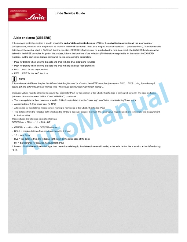
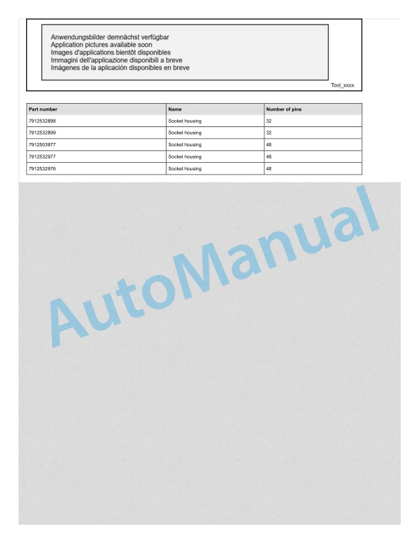
- 1. Service case Release tools for contacts
- 1.1. Table of content
- 1.2. Safety information
- 1.2.1. Safety information for repair and maintenance work
- 1.3. Information
- 1.3.1. Information
- 1.4. Overview
- 1.4.1. Overview of service cases
- 1.5. Plug systems
- 1.5.1. ATS 2.8 plug connector
- 1.5.2. CMC plug connector
- 1.5.3. DCS 9.5 plug connector
- 1.5.4. DIN 1.5mm circular connector
- 1.5.5. DIN 2.5mm circular connector
- 1.5.6. Deutsch DTM plug connector
- 1.5.7. ECU appliance plug
- 1.5.8. MCON appliance plug
- 1.5.9. Appliance plug with JPT and MQS contacts
- 1.5.10. Appliance plug with MT2 and JPT contacts
- 1.5.11. SICMA appliance plug
- 1.5.12. Econoseal JMark 2 plug connector
- 1.5.13. Elobau 11pin receptacle housing
- 1.5.14. E5931 plug connector
- 1.5.15. FASTINFASTON 6.3mm plug connector
- 1.5.16. GT150 plug connector
- 1.5.17. HDSCS plug connector
- 1.5.18. JPT plug connector
- 1.5.19. JPT SLD plug connector
- 1.5.20. JPT plug connector Saab
- 1.5.21. JPT plug connector VW
- 1.5.22. Kompakt 1.1 plug connector
- 1.5.23. Bosch Kompakt 4 plug connector
- 1.5.24. Leavyseal plug connector
- 1.5.25. MCON 1.2mm LL plug connector
- 1.5.26. MCON 1.2mm CB plug connector
- 1.5.27. MCP plug connector
- 1.5.28. MetriPack 150 plug connector
- 1.5.29. MiniFit plug connector
- 1.5.30. Mini Universal MATENLOK plug connector
- 1.5.31. Mini relay socket for DFK 1.3 and MDK 1.3
- 1.5.32. MKR Plus plug connector
- 1.5.33. MQS plug connector
- 1.5.34. MR plug connector
- 1.5.35. MTA plug housing and fuse housing
- 1.5.36. MT2 plug connector
- 1.5.37. MT2 1.5mm plug connector VW
- 1.5.38. Multilock plug connector
- 1.5.39. MX150 plug connector
- 1.5.40. NG1 plug connector
- 1.5.41. Phönix Contact HC plug connector
- 1.5.42. PT 3F plug connector
- 1.5.43. Relay socket with SPT contacts for DFK 1.3.4 and MDK 1.3.4
- 1.5.44. Relay socket with SPT and MPT contacts
- 1.5.45. Fuse holder with SPT contacts
- 1.5.46. Sicma plug connector
- 1.5.47. SLK 2.8 plug connector
- 1.5.48. Souriau UTL7 plug connector
- 1.5.49. Superseal 1.5mm plug connector
- 1.5.50. Trident Neptune plug connector
- 1.5.51. Universal MATENLOK plug connector
- 1.5.52. VW 9.5mm plug connector
- 2. Electric TruckModels E18S.E20S
- 2.1. Table of content
- 2.2. Product information
- 2.2.1. Tightening torques
- 2.2.1.1. Tightening torques for standard pitch threads
- 2.2.1.2. Tightening torques for fine pitch threads
- 2.2.1.3. Special torque
- 2.2.2. Diagnostic software
- 2.2.2.1. CAN box
- 2.2.2.2. Software update
- 2.2.2.3. Pathfinder
- 2.2.2.4. Log files
- 2.2.2.5. Code lists
- 2.2.2.6. Error codes
- 2.3. Motor
- 2.3.1. Drive axle PMS621
- 2.3.1.1. Overview of drive axle
- 2.3.1.2. Filling the gearbox
- 2.3.1.3. Oil draining
- 2.3.2. Drive motor
- 2.3.2.1. Drive motor
- 2.3.2.2. Motor terminals
- 2.3.3. Sensors
- 2.3.3.1. Drive axle temperature sensor
- 2.3.3.2. Incremental transducer
- 2.4. Gearbox
- 2.4.1. Planetary transmission
- 2.4.1.1. Drive axle parts
- 2.5. Chassis, bodywork and fittings
- 2.5.1. Chassis
- 2.5.1.1. Overhead guard
- 2.5.1.2. Replacing operator presence switch
- 2.5.1.3. Battery compartment
- 2.5.1.4. Drive axle and steering axle
- 2.6. Steering
- 2.6.1. Steering system
- 2.6.1.1. Steering system
- 2.6.1.2. Compact steering axle features
- 2.6.2. Steering angle sensor
- 2.6.2.1. Steering angle sensor
- 2.6.3. Steering column sensor 3B2
- 2.6.3.1. Steering column sensor 3B2
- 2.6.3.2. Changing the steering column sensor 3B2
- 2.6.4. Wheels and tires
- 2.6.4.1. Tyre specifications
- 2.7. Controls
- 2.7.1. Operating handle
- 2.7.1.1. Overview of the joystick
- 2.7.1.2. Joystick function
- 2.7.1.3. MFH joystick
- 2.7.2. Brake system
- 2.7.2.1. General
- 2.7.2.2. Brake system
- 2.7.2.3. Electrical connection
- 2.7.2.4. Troubleshooting and fault elimination
- 2.8. Electrics . Electronics
- 2.8.1. General
- 2.8.1.1. Safety instructions for electrical equipment
- 2.8.1.2. Cleaning the electrical system
- 2.8.1.3. Insulation test
- 2.8.1.4. EMC Electromagnetic compatibility
- 2.8.1.5. CAN bus
- 2.8.1.6. Electrostatic charging
- 2.8.1.7. Functional description
- 2.8.1.8. Layout of main electrical components
- 2.8.2. Control unit
- 2.8.2.1. Overview of control unit
- 2.8.2.2. Control unit specifications
- 2.8.2.3. Control unit pins
- 2.8.2.4. Power supply
- 2.8.3. Vehicle Control Master
- 2.8.3.1. Overview of Vehicle Control Master
- 2.8.3.2. Introduction
- 2.8.3.3. Vehicle Control Master specifications
- 2.8.3.4. Vehicle Control Master pins
- 2.8.4. Electrical components
- 2.8.4.1. Main contactor
- 2.8.4.2. Main current fuses
- 2.8.4.3. Emergency stop switch
- 2.8.4.4. Fuse box
- 2.8.4.5. Discharging circuit
- 2.8.4.6. Voltage transformers
- 2.8.4.7. Battery plug connector
- 2.8.4.8. Lighting switches
- 2.8.5. Display unit
- 2.8.5.1. Display unit
- 2.8.5.1.1. Display unit
- 2.8.5.1.2. Pin definition of the display
- 2.8.5.1.3. Display unit introduction
- 2.9. Hydraulics
- 2.9.1. General
- 2.9.1.1. Hydraulic System Parameter
- 2.9.1.2. Hydraulic system contamination
- 2.9.2. Hydraulic pump unit
- 2.9.2.1. Hydraulic pump unit
- 2.9.2.2. Hydraulic control valve
- 2.9.3. Control valve unit
- 2.9.3.1. Priority valve
- 2.9.3.2. Emergency lowering screw
- 2.9.4. Hydraulic components
- 2.9.4.1. Highpressure filter
- 2.9.4.2. Tilt cylinder
- 2.10. Load lift system
- 2.10.1. Mast
- 2.10.1.1. Safety information for lift mast operations
- 2.10.1.2. Lift mast chains
- 2.10.1.3. Adjusting the lift mast chain
- 2.10.2. Lift mast
- 2.10.2.1. Fork arms (basic type)
- 2.10.2.2. Fork carriage (basic type)
- 2.10.2.3. Mast (basic type)
- 2.10.2.4. Basic line
- 2.10.2.5. Chains
- 2.10.2.6. Rupture valve
- 3. Circuit diagramsElectric forklift truck1346_E18S, 1346_E20S
- 3.1. Table of content
- 3.2. Circuit diagrams
- 3.2.1. Wire diagram
- 3.2.1.1. Wire Diagram 1
- 3.2.1.2. Wire Diagram 2
- 3.2.1.3. Wire Diagram 3
- 3.2.2. Hydraulic diagram
- 3.2.2.1. Hydraulic diagram
Rate this product
You may also like


Linde Workshop Manual PDF
$50.00


Linde Workshop Manual PDF
Linde 1102-01 – ECR27, ECR36 Production site LMH-NA Workshop Manuals
$50.00
- Claas
- Grove
- New Holland
- Komatsu
- Kubota
- John Deere
- Linde
- Bomag
- CASE
- Clark
- JCB
- Jungheinrich
- Linde
- Yale
- Yanmar
- Manitou
- Manitowoc
- CNH
- Doosan
- Fiatagri
- Fiatallis
- Fiatallis Other Manual PDF
- Flexi Coil
- Ford New Holland
- Ford New Holland Other Manual PDF
- Huyndai
- Hypac
- Hyster
- Hyster Service Manual PDF
- Isuzu
- Kobelco
- Kohler
- Krupp
- Lombardini
- Mahindra
- Nuvera
- Perkins
- Sperry New Holland
- Utilev
- Versatile
- ZF