Linde 8918-01 – MT12C, MT15C Production site Xiamen Workshop Manuals SN CT8918M00001 and up
$40.00
- Type Of Manual: Workshop Manuals
- Manual ID: SN CT8918M00001 and up
- Format: PDF
- Size: 20.7MB
- Number of Pages: 148
- Serial Number:
SN CT8918M00001 and up
Category: Linde Workshop Manual PDF
-
Model List:
- MT12C
- MT15C
- 1. Electric pallet truckMT12C . MT15C
- 1.1. Table of content
- 1.2. Product information
- 1.2.1. Truck information
- 1.2.1.1. Technical description
- 1.2.1.2. General view
- 1.2.2. Aftersales service
- 1.2.2.1. Overview
- 1.2.2.2. Safety warnings
- 1.2.2.3. Operating tool
- 1.2.2.3.1. Commonly used tools
- 1.2.2.3.2. Torque for standard parts
- 1.2.2.4. Handheld unit
- 1.2.2.4.1. Handheld unit
- 1.2.2.4.2. Connecting the handheld unit
- 1.2.2.4.3. Handheld unit main screen
- 1.2.2.5. Maintenance and servicing
- 1.2.2.5.1. Cleaning the truck
- 1.2.2.5.2. Checks and maintenance
- 1.2.2.5.3. Service plan table
- 1.2.2.5.4. Inspection and maintenance data
- 1.2.2.6. LED fault indicator light diagnostic
- 1.2.2.6.1. Fault indicator light
- 1.2.2.6.2. LED fault indicator diagnosis
- 1.2.2.7. Troubleshooting
- 1.2.2.7.1. Preparation before troubleshooting
- 1.2.2.7.2. Testing the battery voltage
- 1.2.2.7.3. Troubleshooting solutions to common faults
- 1.2.2.8. Aftersales software
- 1.2.2.8.1. Aftersales software
- 1.2.2.8.2. Linde Service Guide (LSG) diagnostics
- 1.2.3. Internal test specifications
- 1.2.3.1. Insulation test
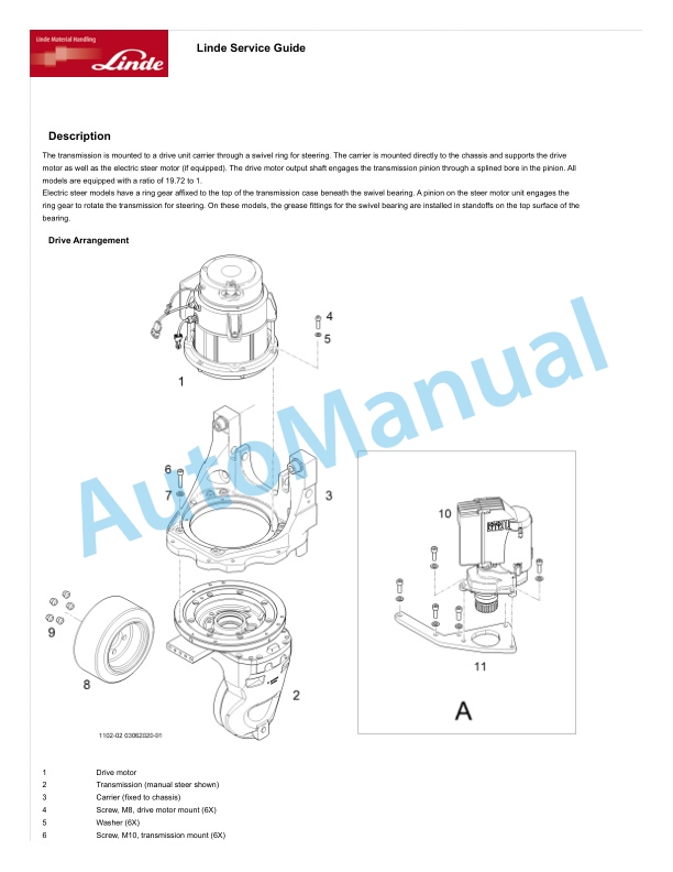
- 1.3. Drive mechanism and transmission system
- 1.3.1. Drive assembly
- 1.3.1.1. Drive assembly
- 1.3.1.2. Removing and installing
- 1.3.2. Electromagnetic brake
- 1.3.2.1. Electromagnetic brake
- 1.3.2.2. Removing and installing
- 1.3.2.3. Malfunctions and causes
- 1.3.2.4. Checking and testing
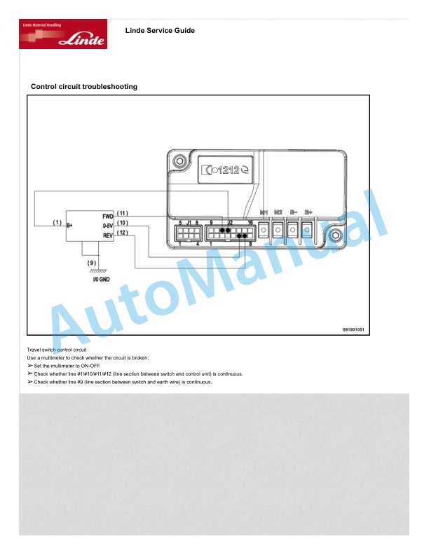
- 1.3.2.5. Control circuit troubleshooting
- 1.3.3. Drive wheel
- 1.3.3.1. Removing and installing
- 1.3.3.2. Malfunctions and causes
- 1.3.4. Drive motor
- 1.3.4.1. Removing and installing
- 1.3.4.2. Malfunctions and causes
- 1.3.4.3. Checking and testing
- 1.3.5. Gearbox
- 1.3.5.1. Removing and installing
- 1.3.5.2. Malfunctions and causes
- 1.4. Chassis and bodywork
- 1.4.1. Load wheel
- 1.4.1.1. Removing and installing
- 1.4.1.2. Malfunctions and causes
- 1.4.2. Front platform
- 1.4.2.1. Removing and installing
- 1.4.3. Cowling
- 1.4.3.1. Removing and installing
- 1.4.4. Castors
- 1.4.4.1. Removing and installing
- 1.4.5. Lifting mechanism
- 1.4.5.1. Checking the fork
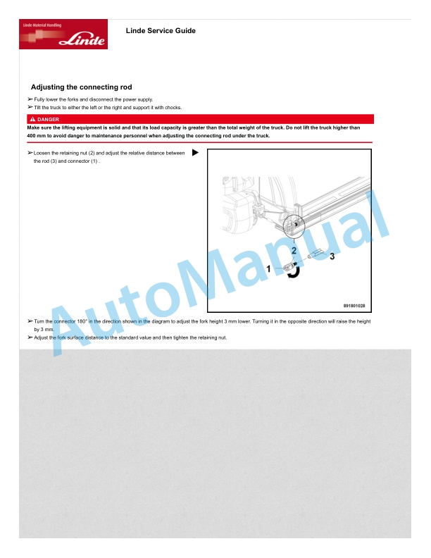
- 1.4.5.2. Adjusting the connecting rod
- 1.4.5.3. Removing and installing
- 1.5. Drivers compartment
- 1.5.1. Structure and function
- 1.5.2. Operating handle
- 1.5.2.1. Operating handle
- 1.5.3. Pushbutton switch
- 1.5.3.1. Pushbutton switch
- 1.5.3.2. Removing and installing
- 1.5.3.3. Malfunctions and causes
- 1.5.3.4. Checking and testing
- 1.5.3.5. Control circuit troubleshooting
- 1.5.4. Drive switch
- 1.5.4.1. Drive switch
- 1.5.4.2. Malfunctions and causes
- 1.5.4.3. Checking and testing
- 1.5.4.4. Control circuit troubleshooting
- 1.5.5. Key switch
- 1.5.5.1. Key switch
- 1.5.5.2. Malfunctions and causes
- 1.5.5.3. Checking and testing
- 1.6. Electric.electronic module
- 1.6.1. Control unit (1212E)
- 1.6.1.1. Removing and installing
- 1.6.1.2. Control unit interface function
- 1.6.2. Interlock switch
- 1.6.2.1. Removing and installing
- 1.6.2.2. Malfunctions and causes
- 1.6.2.3. Checking and testing
- 1.6.2.4. Control circuit troubleshooting
- 1.6.3. Fuse
- 1.6.3.1. Fuses
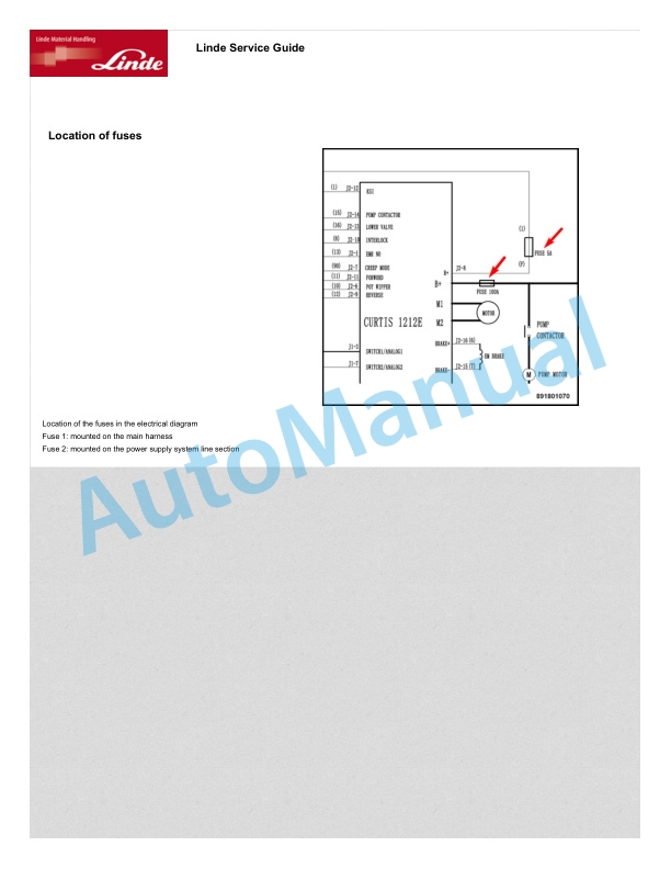
- 1.6.3.2. Location of fuses
- 1.6.3.3. Checking and testing
- 1.6.4. Lithiumion battery
- 1.6.4.1. Safety and warnings
- 1.6.4.2. Using the lithiumion battery
- 1.6.4.3. Maintenance and servicing
- 1.6.4.3.1. Maintenance of lithiumion batteries
- 1.6.4.3.2. Storage
- 1.6.4.3.3. Determining whether charging is normal
- 1.6.4.3.4. Determining whether the battery is normal
- 1.6.4.4. Lithiumion battery charging
- 1.6.4.4.1. Accessories
- 1.6.4.4.2. Charging precautions
- 1.6.4.4.3. External charging
- 1.6.4.4.4. Battery parameters
- 1.7. Hydraulic system
- 1.7.1. Hydraulic system
- 1.7.2. Hydraulic station
- 1.7.2.1. Removing and installing
- 1.7.2.2. Hydraulic station assembly
- 1.7.3. Pump motor
- 1.7.3.1. Removing and installing
- 1.7.3.2. Malfunctions and causes
- 1.7.3.3. Checking and testing
- 1.7.4. Pump contactor
- 1.7.4.1. Pump contactor
- 1.7.4.2. Removing and installing
- 1.7.4.3. Malfunctions and causes
- 1.7.4.4. Checking and testing
- 1.7.5. Solenoid valve
- 1.7.5.1. Solenoid valve
- 1.7.5.2. Malfunctions and causes
- 1.7.5.3. Checking and testing
- 1.7.6. Cylinder
- 1.7.6.1. Cylinder removal precautions
- 1.7.6.2. Cylinder installation precautions
- 1.7.6.3. Removing and installing
- 1.7.7. Hydraulics troubleshooting
- 1.7.7.1. Hydraulics troubleshooting
- 1.8. Schematic diagrams
- 1.8.1. Hydraulics diagrams
- 1.8.2. Electrical diagrams
- 1.8.2.1. Electrical diagrams
- 1.8.2.2. Wiring diagram
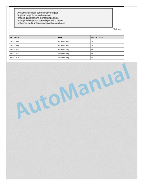
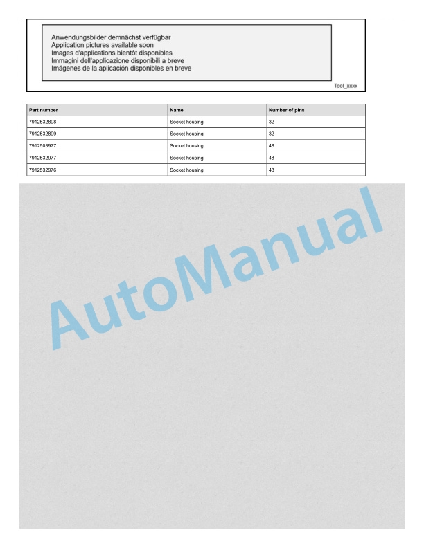
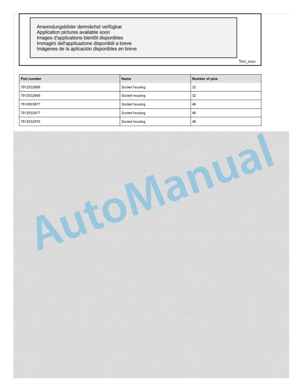
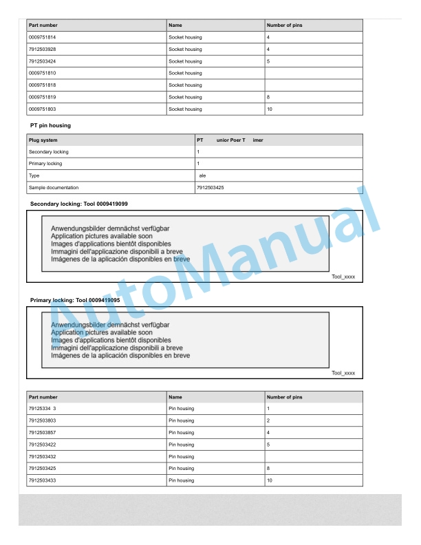
- 1.8.3. Harness and connector
Rate this product
You may also like
Linde Workshop Manual PDF
Linde 1103-02 – ETR50 Production site LMH-NA Workshop Manuals SN A11103V00001 and up
$40.00
Linde Workshop Manual PDF
$40.00
Linde Workshop Manual PDF
Linde 1102-02 – ECR30, ECR40 Production site LMH-NA Workshop Manuals SN A11102V00001 and up
$40.00

