


New Holland Service Manual PDF
New Holland 100, 115, 135, 160 HP Tractor Repair Manual 6035432100
$30.00
New Holland Service Manual PDF
New Holland 1400, 1500 Combine Tractor Service Manual 40481300
$30.00
New Holland Service Manual PDF
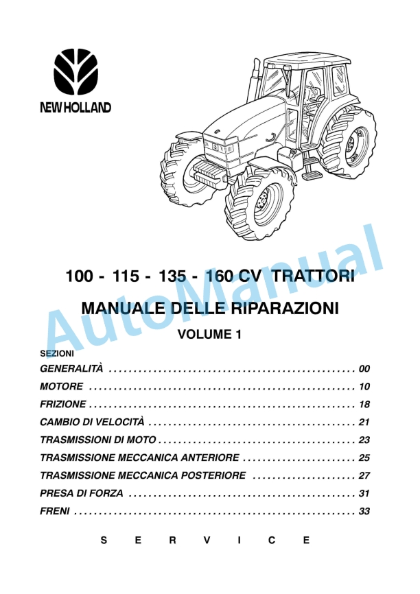
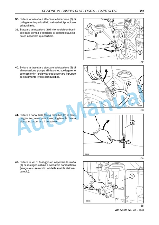
New Holland 100, 115, 135, 160 CV Tractor Repair Manual 6035432000 ITA
$30.00
New Holland Service Manual PDF
New Holland 12.9L Turbo Compound Engine Repair Manual 87737594
$30.00
New Holland Service Manual PDF
New Holland 130 Speedrower Self-Propelled Windrower Service Manual 47698328
$30.00

