


Yanmar 2TNV70 to 4TNV106T Application Manual
$20.00
- Type Of Manual: Application Manual
- Number of Pages: 235
- Size: 13.4MB
- Format: PDF
Category: Yanmar Operator Manual PDF
-
Model List:
- 2TNV70, 3TNV70, 3TNV76, 3TNV82A, 3TNV82A-B, 3TNV84, 3TNV84T, 3TNV84T-B, 3TNV88, 3TNV88-B, 3TNV88-U, 4TNV84, 4TNV84T, 4TNV84T-Z, 4TNV88, 4TNV88-B, 4TNV88-U, 4TNV94L, 4TNV98, 4TNV98-Z, 4TNV98-E, 4TNV98T, 4TNV98T-Z, 4TNV106, 4TNV106T
- 1. Application Standard
- 1.1. Application Standard
- 1.2. Special Operating Environment
- 1.2.1. Precautions Against Dusty Conditions
- 1.2.2. Precautions for Outdoor Installation
- 1.2.3. Precautions Against Salty Conditions (Air, Sea Water, Road Salt)
- 1.2.4. Precautions Against Cold Environment
- 1.2.5. Precautions Against Hot Environment
- 1.3. Low-temperature startability
- 1.3.1. Combination of Starting Devices for Each Driven Machine
- 1.3.1.1. IDI Series
- 1.3.1.2. DI Series
- 1.3.2. Allowable Air Intake Restriction and Exhaust Back Pressures
- 1.3.2.1. Allowable Air Intake Restriction
- 1.3.2.2. Allowable Exhaust Back Pressure
- 1.3.2.3. The Necessity of Intake/Exhaust Pressure Settings for Engine with EGR
- 1.3.2.4. The characteristics of Intake/Exhaust Pressure for the engine with EGR
- 1.3.2.5. The Intake/Exhaust Pressure is changed because of changing the open level of EGR depending on the load rate for the engine with EGR. See Figure 1-2 below as the example. It is also changed depending on the engine rated speed.
- 1.3.2.6. Note point at the Intake/Exhaust Pressure Settings for the engine with EGR
- 1.3.2.7. NV84T-Z
Allowable Intake/Exhaust Pressure Settings (at rated output) - 1.3.2.8. NV98-Z
Allowable Intake/Exhaust Pressure Settings (at rated output) - 1.3.2.9. NV98-E/Z
Allowable Intake/Exhaust Pressure Settings (at rated output) - 1.3.2.10. NV98T-Z
Allowable Intake/Exhaust Pressure Settings (at rated output) - 1.3.2.11. NV98T-Z
Allowable Intake/Exhaust Pressure Settings (at rated output) - 1.3.3. EPA Emission Control Regulations for Non-road Diesel Engine (Requirements for the Driven Machine Manufacturers)
- 1.3.4. Engine Output
- 1.3.5. Emission Control Label
- 1.3.6. Fuel Inlet Label
- 1.3.7. Installation Evaluation
- 1.3.8. Engine Maintenance
- 1.3.9. Tamper Resistance
- 1.3.10. Report on Sales in the USA
- 1.3.11. Recall – EPA
- 2. Engine Model Selection
- 2.1. Model Designation
- 2.2. Engine Classification
- 2.2.1. Classification with Injection System
- 2.2.2. Classification with Displacement
- 2.2.3. Classification with Engine Speed
- 2.2.4. Engine Classification with Above Mentioned Conditions
- 2.3. Standard Engines for Driven Machines
- 2.3.1. Classification of Standard Engines for Driven Machines
- 2.3.1.1. Engine Model Nomenclature
- 2.3.1.2. Model Name of Engine by Driven Machines and Category
- 2.3.2. Specifications of Standard Engines for Driven Machines
- 2.3.2.1. Machine standard engine (NV1 to complies with EPA Tier4)
- 2.3.2.2. Machine standard engine (NV2 to complies with EPA Tier2)
- 2.3.2.3. Machine standard engine (NV2 to complies with EPA Interim Tier4)
- 2.3.2.4. Machine standard engine (NV3 to complies with EPA Tier2)
- 2.3.2.5. Machine standard engine (NV3 to complies with EPA Interim Tier4, Tier3)
- 3. Specifications
- 3.1. Atmospheric Conditions and Engine Configuration Affect Engine Output
- 3.1.1. Engine Output for Industrial Use
- 3.1.2. Engine Output for Generator Use
- 3.2. Specifications
- 3.2.1. IDI Series
- 3.2.1.1. NV70 (complies with EPA Tier4)
- 3.2.1.2. NV70 (complies with EPA Tier4)
- 3.2.1.3. NV76 (complies with EPA Tier4)
- 3.2.2. DI Series
- 3.2.2.1. NV82A (complies with EPA Tier2)
- 3.2.2.2. NV82A-B/-Z (complies with EPA Interim Tier4)
- 3.2.2.3. NV82A-B 3TNV82A-Z (Electronically controlled)
- 3.2.2.4. NV84 (complies with EPA Tier2)
- 3.2.2.5. NV84T-Z (Electronically controlled)
- 3.2.2.6. NV88 (complies with EPA Tier2)
- 3.2.2.7. NV88-U/-E (complies with EPA Interim Tier4)
- 3.2.2.8. NV88-U 3TNV88-E (Electronically controlled)
- 3.2.2.9. NV88-B/-Z (complies with EPA Interim Tier4)
- 3.2.2.10. NV88-B 3TNV88-Z (Electronically controlled)
- 3.2.2.11. NV84T (complies with EPA Tier2)
- 3.2.2.12. NV84T-B (complies with EPA Interim Tier4)
- 3.2.2.13. NV84 (complies with EPA Tier2)
- 3.2.2.14. NV88 (complies with EPA Tier2)
- 3.2.2.15. NV88-U/-E (complies with EPA Interim Tier4)
- 3.2.2.16. NV88-U 4TNV88-E (Electronically controlled)
- 3.2.2.17. NV88-B/-Z (complies with EPA Interim Tier4)
- 3.2.2.18. NV88-B 4TNV88-Z (Electronically controlled)
- 3.2.2.19. NV84T (complies with EPA Tier2)
- 3.2.2.20. NV84T-Z/-B (complies with EPA Interim Tier4)
- 3.2.2.21. NV84T-Z
- 3.2.2.22. NV94L (complies with EPA Tier2)
- 3.2.2.23. NV98 (complies with EPA Tier2)
- 3.2.2.24. NV98-E (complies with EPA Interim Tier4)
- 3.2.2.25. NV98-E
- 3.2.2.26. NV98-Z (complies with EPA Interim Tier4)
- 3.2.2.27. NV98-Z
- 3.2.2.28. NV98T (complies with EPA Tier2)
- 3.2.2.29. NV98T-Z (complies with EPA Tier3)
- 3.2.2.30. NV98T-Z
- 3.3. Dimensions
- 3.3.1. IDI Series
- 3.3.2. DI Series
- 3.3.2.1. NV82A/3TNV82A-B
- 3.3.2.2. NV82A-B 3TNV82A-Z (Electronically controlled)
- 3.3.2.3. NV84/3TNV88/3TNV88-U/3TNV88-B
- 3.3.2.4. NV88-U/3TNV88-B 3TNV88-E/3TNV88-Z (Electronically controlled)
- 3.3.2.5. NV84T-B
- 3.3.2.6. NV84T
- 3.3.2.7. NV84T-Z
- 3.3.2.8. NV84T-Z
- 3.3.2.9. NV84/4TNV88/4TNV88-U/4TNV88-B
- 3.3.2.10. NV88-U/4TNV88-B 4TNV88-E/4TNV88-Z (Electronically controlled)
- 3.3.2.11. NV84T-Z
- 3.3.2.12. NV84T-Z
- 3.3.2.13. NV84T
- 3.3.2.14. NV94L/4TNV98
- 3.3.2.15. NV98-E/4TNV98-Z
- 3.3.2.16. NV98-E/4TNV98-Z
- 3.3.2.17. NV98T-Z
- 3.3.2.18. NV98T-Z (Conforming to EPA Tier 3 Standards)
- 3.3.2.19. NV98T
- 4. Correcting Observed Power
- 4.1. Power Corrections
- 4.1.1. Correction Formula (A)
- 4.1.2. Correction Formula (B)
- 4.1.3. Corrections for Reducing Exhaust Smoke Density at Altitude
- 4.2. Atmospheric Pressure Calculation for Change in Altitude
- 4.3. Atmospheric Temperature Calculation for Change in Altitude
- 4.4. Relationships among Altitude, Atmospheric Pressure and Atmospheric Temperature
- 4.5. How to Obtain Relative Humidity by Dry and Wet-Bulb Thermometer
- 4.6. Relationship between Atmospheric Temperature and Saturation Vapor Pressure
- 4.7. Altitude Characteristics
- 4.7.1. Reduction of Output
- 4.7.2. Reduction of Torque-rise (Reduction of Maximum Torque)
- 4.7.3. Startability at Each Altitude
- 4.7.4. Exhaust White Smoke
- 4.7.5. Misfire at High Altitude
- 5. Engine Performance
- 5.1. Performance Curves
- 5.1.1. Output Curve P
- 5.1.2. Specific Diesel Fuel Consumption Curve f
- 5.2. Torque Curve T
- 5.3. Partial Recovery Ratio
- 5.4. Governor Performance
- 5.4.1. Governor Performance of TNV Series Engines
- 6. Cold Starting Aids
- 6.1. Glow Plug
- 6.1.1. Glow Plug Structure
- 6.1.2. Control Circuit Diagram for Standard Glow Plug
- 6.1.3. Control Circuit Parts for Glow Plug
- 6.1.3.1. Pattern of Key Switch Terminal Yanmar Part No. 129115 – 91250
- 6.1.3.2. Timer and Preheat Indicator
- 6.1.3.3. Relay for Starting Aids (Power Relay)
- 6.1.4. Control Circuit Diagram for On-Glow (Mechanical Governor)
- 6.1.4.1. Controller (IDI)
- 6.1.4.2. Controller (IDI)
- 6.1.4.3. Power Relay
- 6.1.4.4. Engine Coolant Temperature Switch
- 6.1.5. Control Circuit Diagram for On-Glow (Eco Governor)
- 6.1.5.1. After-Heat (Eco Governor Option)
- 6.2. Inlet Air Heater
- 6.2.1. Inlet Air Heater Structure
- 6.2.2. Control Circuit Diagram for Standard Inlet Air Heater
- 6.2.3. Inlet Air Heater Capacity and Power Relay
- 6.2.4. Control Circuit for Specific Driven Machine Applications
- 6.2.5. Inlet Air Heater Control Circuit Components
- 6.2.5.1. Key Switch Terminal Pattern
- 6.2.5.2. Timer and Preheat Indicator
- 6.2.6. After-Heat (Eco Governor Option)
- 6.2.6.1. Relay for Starting Aids
- 6.2.7. Control Circuit Diagram for On-Glow (Eco Governor)
- 6.2.7.1. After-Heat (Eco Governor Option)
- 6.2.7.2. Relay for Starting Aids
- 6.3. Engine Block Heater
- 6.3.1. Block Heater Configuration
- 6.3.2. Block Heater Connection Diagram
- 6.4. Cold Start Device (CSD) for MP Pump
- 6.4.1. Features of CSD
- 6.4.2. Confirmation of Safety at Cold Start
- 7. Air Intake System
- 7.1. Air Capacity Required for Combustion
- 7.1.1. Calculation of the Air Capacity
- 7.1.1.1. Air Capacity Required for Combustion
- 7.1.1.2. Apparent Air Capacity
- 7.1.2. Air Cleaner Selection Table
- 7.2. Air Cleaner
- 7.2.1. Dust Removing Principle of the Air Cleaner
- 7.2.2. Structure of Air Cleaner
- 7.2.2.1. Types of Air Cleaner Element
- 7.2.2.2. Structure of Single Element Type
- 7.2.2.3. Structure of Double Element Type
- 7.2.3. Dust Indicator
- 7.2.3.1. Mechanical Dust Indicator Part Code 126650-12680
- 7.2.3.2. Electric Dust Indicator Part Code 119140-12680
- 7.2.4. Air Cleaner Installation
- 7.2.5. Air Intake System Hose Routing
- 7.2.5.1. Intake Port Position
- 7.3. Air Intake Restriction
- 7.3.1. Measurement of Air Intake Restriction
- 7.3.2. Allowable Air Intake Restriction
- 8. Exhaust System
- 8.1. In-Use Testing Requirements
- 8.2. EGR Equipment
- 8.2.1. Role and Operation of EGR
- 8.2.2. Structure of Each Device
- 8.2.2.1. EGR Valve
- 8.2.2.2. EGR Cooler
- 8.2.2.3. Lead Valve
- 8.3. Intake/Exhaust Pressure
- 8.4. Turbocharger
- 8.4.1. Structure of Turbocharger
- 8.4.2. Handling the Turbocharger
- 8.5. Exhaust Back Pressure
- 8.5.1. Allowable Exhaust Back Pressure
- 8.6. Exhaust Muffler
- 8.7. Fitting Precautions for Exhaust System
- 8.7.1. Installation of Exhaust Muffler
- 8.7.2. Routing of Exhaust System Components
- 8.8. Exhaust Gas Volume and Exhaust Back Pressure
- 8.8.1. Exhaust Gas Volume
- 8.8.1.1. Combustion Gas Volume
- 8.8.1.2. Exhaust Gas Volume
- 8.8.1.3. Exhaust Back Pressure
- 8.8.2. Total Back Pressure of Exhaust System P
- 8.8.3. Materials for Calculating Exhaust Back Pressure
- 8.9. Black Smoke Exhaust
- 8.9.1. Characteristic Factors of Black Smoke Generation
- 8.9.2. Measurement of Smoke Density
- 9. Cooling System
- 9.1. Cooling System Diagram
- 9.2. Engine Coolant
- 9.2.1. Characteristics of Water
- 9.2.2. Water Quality Needed to Prepare Engine Coolant
- 9.2.3. Required Engine Coolant Characteristics
- 9.2.4. Typical Properties of LLC (Yanmar Standard)
- 9.3. Radiator
- 9.3.1. Example of the structure of a radiator made from aluminum
- 9.3.2. Radiator Selection
- 9.3.3. Radiator Position
- 9.3.3.1. Pusher Fan
- 9.3.3.2. Puller Fan
- 9.3.4. Radiator Standard Capacity
- 9.3.5. Precautions for Installation
- 9.3.5.1. Installation example of an aluminum radiator with resin tank
- 9.3.5.2. Notes on installation
- 9.3.5.3. Other Precautions
- 9.4. Cooling System Hoses
- 9.4.1. Rubber Hose Conditions
- 9.4.2. Precautions for Cooling System Hoses
- 9.4.3. Hose Clamps
- 9.4.4. Supplying Engine Coolant
- 9.5. Thermostat
- 9.5.1. Operation of Thermostat and Flow of Coolant
- 9.5.1.1. Under cold conditions
- 9.5.1.2. Under warm conditions
- 9.6. Engine Coolant Temperature Switch
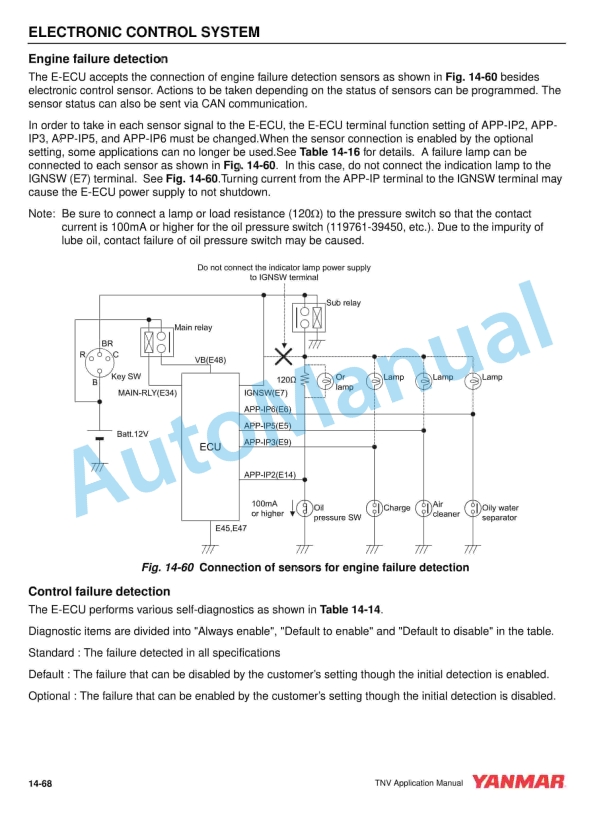
- 9.6.1. Example of wiring diagram
- 9.7. Cooling System Recovery Tank
- 9.7.1. Radiator Cap Structure
- 9.7.2. Function of Cooling System Recovery Tank
- 9.7.3. Selection of Engine Coolant Recovery Tank Capacity
- 9.7.4. Installation of Engine Coolant Recovery Tank
- 9.8. Heat Rejection to Engine Coolant
- 9.8.1. Calculation of Heat Rejection to Engine Coolant
- 9.8.2. Discharge Engine Coolant Flow from Engine Coolant Pump
- 9.9. Cooling Fan and Its Drive System
- 9.9.1. Cooling Fan
- 9.9.1.1. Selection of Cooling Fan
- 9.9.1.2. Pusher Fan / Puller Fan
- 9.9.1.3. Material and Deformation of the Cooling Fan
- 9.9.1.4. Fan Spacer
- 9.9.1.5. V-pulley
- 10. Diesel Fuel System
- 10.1. Fuel Inlet Label
- 10.2. Diesel Fuel System Diagram
- 10.2.1. Fuel System (IDI Engine/Equipped with Mechanical Fuel Feed Pump)
- 10.2.2. Fuel System (IDI Engine/Equipped with Electric Fuel Feed Pump)
- 10.2.3. Fuel System (DI Engine/Equipped with Electric Fuel Feed Pump)
- 10.3. Standard Diesel Fuel Line Layout
- 10.3.1. Layout for IDI Engines with ML Type Diesel Fuel Injection Pump
- 10.3.1.1. Diesel Fuel Line Layout for IDI Engines
- 10.3.1.2. Diesel Fuel System Part Names and Functions for IDI Engines
- 10.3.1.3. Layout Dimension for IDI Engines
- 10.3.1.4. Parts Specification for IDI Engines
- 10.3.1.5. Fuel Filter for IDI Engines
- 10.3.2. Layout for DI Engines with MP2 or MP4 Type Fuel Injection Pump
- 10.3.2.1. Fuel Line Layout for DI Engines.
- 10.3.2.2. Diesel Fuel System Part Names and Functions for DI Engines
- 10.3.2.3. Fuel Line Layout (DI engines)
- 10.3.2.4. Parts Specification for Engine
- 10.3.2.5. For poor quality fuel
- 10.4. Diesel Fuel
- 10.4.1. Recommended Diesel Fuel
- 10.4.2. Fuels for Diesel Engines
- 10.4.2.1. Classifications of Mineral Oil
- 10.4.2.2. Fundamental Requirements for Diesel Fuel
- 10.4.2.3. Properties of Diesel Fuel
- 10.4.3. Selection of Diesel Fuel
- 10.4.3.1. Volatile Matter
- 10.4.3.2. Impurities
- 10.4.3.3. Use Diesel Fuels Classified According to Ambient Temperature
- 10.4.4. Engine Trouble Caused by Improper Diesel Fuel
- 10.4.4.1. Deposits on the Exhaust Valve
- 10.4.4.2. Deposits on the Piston Ring Grooves
- 10.4.4.3. Clogging or Corrosion of the Injection Hole of the Fuel Injection Valve
- 10.4.4.4. Sediments Inside the Crankcase
- 10.4.5. Diesel Fuel Properties and Engine Performance
- 10.4.5.1. Deposits in Combustion Chamber
- 10.4.5.2. Startability
Rate this product
You may also like
Yanmar Operator Manual PDF
Yanmar 2TNV70 to 4TNV106T Industrial Engine Operation Manual 0ATNV-G00101
$20.00
Yanmar Operator Manual PDF
Yanmar 2TNV70 to 4TNV106T Industrial Engines Operation Manual 0ATNV-EN0019
$20.00
Yanmar Operator Manual PDF
$20.00
Yanmar Operator Manual PDF
Yanmar 3JH4E, 4JH4AE, 4JH4-TE, 4JH4-HTE Operation Manual 0AJH4-G00103
$20.00
Yanmar Operator Manual PDF
$20.00
Yanmar Operator Manual PDF
$20.00
Yanmar Operator Manual PDF
Yanmar 4CHL-N, 4CHL-TN, 6CHL-N, 6CHL-TN, 6CHL-HTN Marine Auxiliary Engine Operation Manual
$20.00
Yanmar Operator Manual PDF
$20.00