- Claas
- Grove
- New Holland
- Komatsu
- Kubota
- John Deere
- Linde
- Bomag
- CASE
- Clark
- JCB
- Jungheinrich
- Linde
- Yale
- Yanmar
- Manitou
- Manitowoc
- CNH
- Doosan
- Fiatagri
- Fiatallis
- Fiatallis Other Manual PDF
- Flexi Coil
- Ford New Holland
- Ford New Holland Other Manual PDF
- Huyndai
- Hypac
- Hyster
- Hyster Service Manual PDF
- Isuzu
- Kobelco
- Kohler
- Krupp
- Lombardini
- Mahindra
- Nuvera
- Perkins
- Sperry New Holland
- Utilev
- Versatile
- ZF
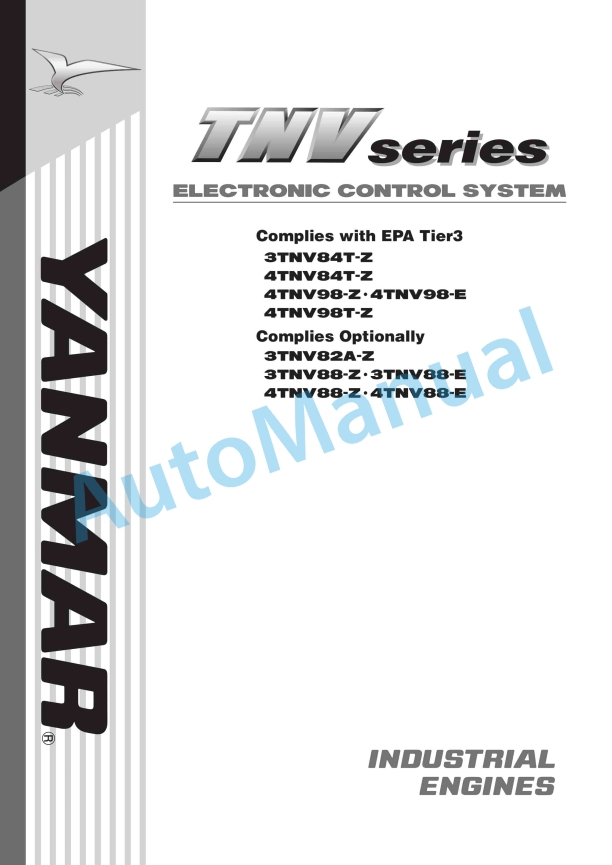
Yanmar TNV Series Electronic Control System
$20.00
- Number of Pages: 152
- Size: 6.0MB
- Format: PDF
-
Model List:
- TNV Series Electronic Control System
- 1. Electronic Control System
- 1.1. Precautions on the use of electronic control components
- 1.1.1. Controller and wire harness
- 1.1.2. Fuel injection pump
- 1.1.3. EGR valve
- 1.1.4. Accelerator sensor
- 1.1.5. Engine diagnosis tool
- 1.2. Control system
- 1.2.1. System outline
- 1.2.1.1. The following describes each of the components shown in Fig. 14-4
- 1.2.1.2. Main relay
- 1.2.1.3. Rack actuator relay
- 1.2.1.4. Sub relay
- 1.2.1.5. Starting aid relay
- 1.2.1.6. Starter relay
- 1.2.1.7. Failure lamp
- 1.2.1.8. Service tool coupler
- 1.2.1.9. Accelerator sensor
- 1.2.1.10. Coolant temperature sensor
- 1.2.1.11. Panel switches and lamps
- 1.2.1.12. About a diode to be inserted in alternator terminal IG
- 1.2.2. Timing of the E-ECU
- 1.2.2.1. Outline
- 1.2.2.2. Requirement
- 1.2.2.3. Current consumption
- 1.2.2.4. Minimum operating voltage
- 1.2.2.5. Minimum detectable speed
- 1.2.2.6. Number of start/stop cycles and duration of energization
- 1.2.2.7. Safety features
- 1.2.2.8. Check for power-up of the E-ECU
- 1.2.2.9. I/O layout
- 1.2.2.10. I/O description
- 1.2.3. Electrical parts
- 1.3. Harness
- 1.3.1. Harness design requirements
- 1.3.1.1. Wiring of the ECU
- 1.3.1.2. Wiring of the starting aid
- 1.3.1.3. Key switch
- 1.3.1.4. General
- 1.3.2. Harness clamping
- 1.3.3. CAN bus termination
- 1.4. Control functions
- 1.4.1. Control software
- 1.4.2. General
- 1.4.2.1. Speed sensor input
- 1.4.2.2. Rack position sensor input
- 1.4.2.3. Coolant temperature sensor input
- 1.4.2.4. Accelerator sensor input
- 1.4.2.5. Contact input
- 1.4.2.6. Contact output
- 1.4.2.7. Rack actuator output
- 1.4.2.8. EGR valve output
- 1.4.3. Engine control – General
- 1.4.3.1. Self-holding of the E-ECU power
- 1.4.3.2. Start control
- 1.4.3.3. Torque curve and engine regulation
- 1.4.3.4. Speed control
- 1.4.3.5. Transition control
- 1.4.3.6. EGR control
- 1.4.3.7. CSD control
- 1.4.3.8. Calculation of load factor
- 1.4.4. Application interface outline
- 1.4.4.1. Droop selection feature (switching droop-isochroous control)
- 1.4.4.2. Isochroous control at low idling
- 1.4.4.3. Accelerator input selection
- 1.4.4.4. Starting aid
- 1.4.4.5. Starter motor start prevention
- 1.4.4.6. Speed selection
- 1.4.4.7. High idling limitation feature
- 1.4.4.8. Engine cutoff
- 1.4.4.9. Emergency stop feature
- 1.4.4.10. Idling speed up
- 1.4.4.11. Blue and white smoke suppression
- 1.4.4.12. Accelerator filter
- 1.4.4.13. Block heater control
- 1.4.4.14. Engine failure detection
- 1.4.4.15. Control failure detection
- 1.4.4.16. CAN communication
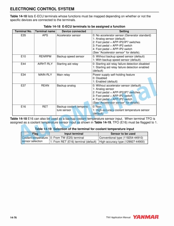
- 1.4.4.17. Terminal assignment
- 1.4.4.18. Operational limitations in failure situations
- 1.4.4.19. Lamp check functional description
- 1.4.5. Engine diagnosis tool function outline
- 1.4.5.1. Data monitor and logging functions
- 1.4.5.2. Logging function
- 1.4.5.3. Tuning function
- 1.5. Fuel injection pump
- 1.6. Coolant temperature sensor
- 1.7. EGR valve
- 1.8. Accelerator sensor
- 1.9. Main relay
- 1.10. Rack actuator relay
- 1.11. Sub relay
- 1.12. Starter relay
- 1.13. Starting aid relay
- 1.13.1. For 400 W air heater (glow plug)
- 1.13.2. For 500/800 W air heater
- 1.13.3. For 1000 W air heater
- 1.14. The Eco-governor checklist
- 1.15. ECU Application Menu
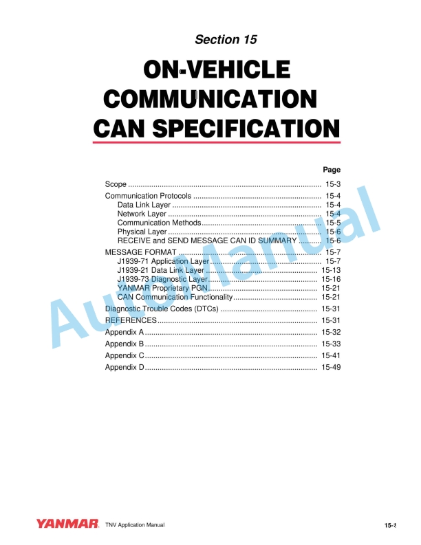
- 2. ON-Vehicle Communication CAN Specification
- 2.1. Communication Protocols
- 2.1.1. Data Link Layer
- 2.1.1.1. Message/Frame Format
- 2.1.1.2. Priority (P)
- 2.1.2. Network Layer
- 2.1.2.1. Addressing
- 2.1.2.2. Address mapping (SA)
- 2.1.3. Communication Methods
- 2.1.4. Physical Layer
- 2.1.4.1. General
- 2.1.4.2. Baud rate
- 2.1.4.3. CAN bit timing
- 2.1.5. RECEIVE and SEND MESSAGE CAN ID SUMMARY
- 2.2. MESSAGE FORMAT
- 2.2.1. J1939-71 Application Layer
- 2.2.1.1. pgn0 – Torque/Speed Control 1 – TSC1 –
- 2.2.1.2. pgn61443 – Electronic Engine Controller 2 – EEC2 –
- 2.2.1.3. pgn61444 – Electronic Engine Controller 1 – EEC1 –
- 2.2.1.4. pgn65188 – Engine Temperature 2 – ET2 –
- 2.2.1.5. pgn65247 – Electronic Engine Controller 3 – EEC3 –
- 2.2.1.6. pgn65253 – Engine Hours, Revolutions – HOURS –
- 2.2.1.7. pgn65255 – Vehicle Hours – VH –
- 2.2.1.8. pgn65259 – Component Identification – CI –
- 2.2.1.9. pgn65260 – Vehicle Identification – VI –
- 2.2.1.10. pgn65262 – Engine Temperature 1 – ET1 –
- 2.2.1.11. pgn65269 – Ambient Conditions – AMB –
- 2.2.1.12. pgn65271 – Vehicle Electrical Power – VEP –
- 2.2.1.13. pgn56320 – Anti-theft Status – ATS –
- 2.2.1.14. pgn56576 – Anti-theft Request – ATR –
- 2.2.2. J1939-21 Data Link Layer
- 2.2.2.1. Acknowledgment
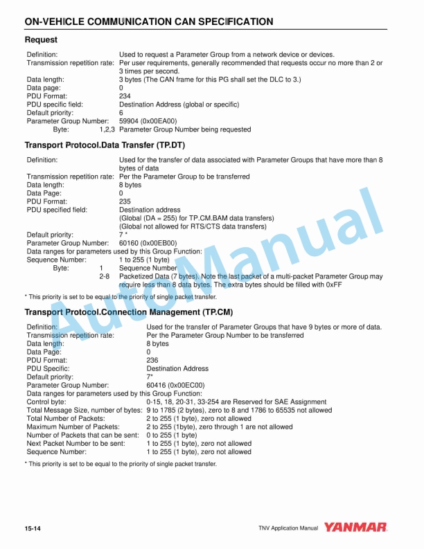
- 2.2.2.2. Request
- 2.2.2.3. Transport Protocol.Data Transfer (TP.DT)
- 2.2.2.4. Transport Protocol.Connection Management (TP.CM)
- 2.2.3. J1939-73 Diagnostic Layer
- 2.2.3.1. ACTIVE DIAGNOSTIC TROUBLE CODES (DM1)
- 2.2.3.2. PREVIOUSLY ACTIVE DIAGNOSTIC TROUBLE CODES (DM2)
- 2.2.3.3. DIAGNOSTIC DATA CLEAR/RESET OF PREVIOUSLY ACTIVE DTCS (DM3)
- 2.2.4. YANMAR Proprietary PGN
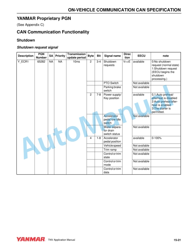
- 2.2.5. CAN Communication Functionality
- 2.2.5.1. Shutdown
- 2.2.5.1.1. Shutdown request signal
- 2.2.5.1.2. Shutdown acknowledgement signal
- 2.2.5.1.3. Shutdown process
- 2.2.5.2. Start Lock
- 2.2.5.2.1. Starter prohibition request signal
- 2.2.5.2.2. Cranking Condition
- 2.2.5.3. Air-Heat function
- 2.2.5.3.1. Preheat/afterheat enable/disable signal
- 2.2.5.3.2. Preheat/afterheat acknowledgement signal
- 2.2.5.3.3. Air-heat function
- 2.2.5.4. Engine Speed control
- 2.2.5.4.1. Speed control signal
- 2.2.5.4.2. Engine speed information signal
- 2.2.5.4.3. Engine Speed control diagram
- 2.2.5.5. CAN communication failure
- 2.2.5.5.1. Detect CAN communication malfunction
- 2.2.5.5.2. Start lock at CAN communication failure mode
- 2.2.5.5.3. Engine speed control at CAN communication failure mode
- 2.2.5.5.4. EECU shutdown at CAN communication failure condition
- 2.2.5.6. Component ID Check
- 2.3. Diagnostic Trouble Codes (DTCs)
- 2.4. REFERENCES
- 2.5. Appendix A
- 2.6. Appendix B
- 2.7. Appendix C
- 2.8. Appendix D
Yanmar Operator Manual PDF
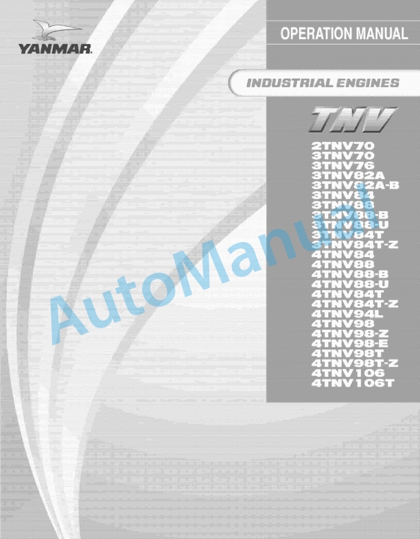
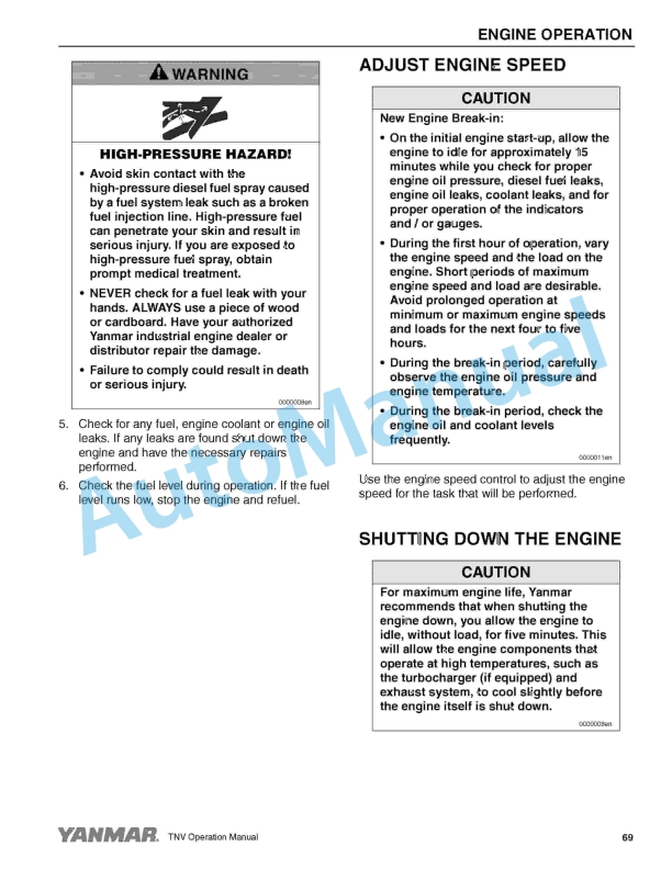
Yanmar 2TNV70 to 4TNV106T Industrial Engines Operation Manual 0ATNV-U00101
Yanmar Operator Manual PDF
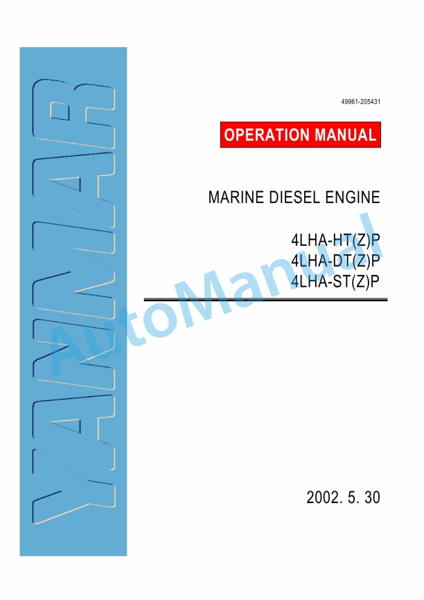
Yanmar 4LHA-HT(Z)P, 4LHA-DT(Z)P, 4LHA-ST(Z)P Marine Diesel Engine Operation Manual
Yanmar Operator Manual PDF
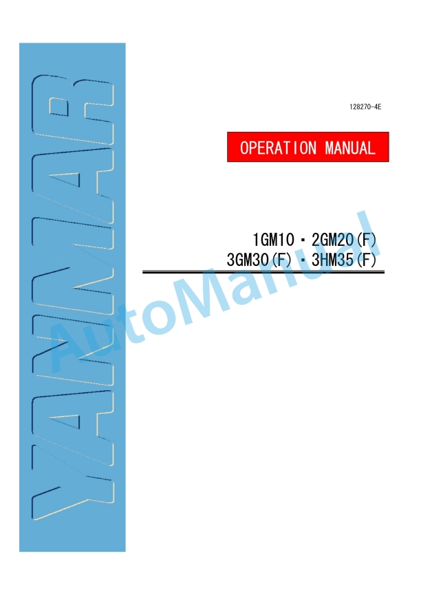
Yanmar 1GM10, 2GM20(F), 3GM30(F), 3HM35(F) Engine Operation Manual
Yanmar Operator Manual PDF
Yanmar 4CHL-N, 4CHL-TN, 6CHL-N, 6CHL-TN, 6CHL-HTN Marine Auxiliary Engine Operation Manual
Yanmar Operator Manual PDF
Yanmar 3TNV74F, 3TNV76F, 3TNV80F, 3TNV80FT, 3TNV88F, 3TNM74F Industrial Engine Operation Manual
Yanmar Operator Manual PDF
Yanmar 4LHA-HTP, 4LHA-DTP, 4LHA-STP, 4LHA-HTZP, 4LHA-DTZP, 4LHA-STZP Marine Engine Operation Manual
Yanmar Operator Manual PDF
Yanmar 3JH4E, 4JH4AE, 4JH4-TE, 4JH4-HTE Operation Manual 0AJH4-G00102
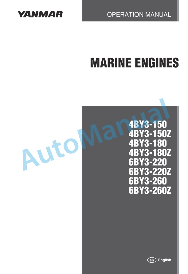
Yanmar Operator Manual PDF
- Claas
- Grove
- New Holland
- Komatsu
- Kubota
- John Deere
- Linde
- Bomag
- CASE
- Clark
- JCB
- Jungheinrich
- Linde
- Yale
- Yanmar
- Manitou
- Manitowoc
- CNH
- Doosan
- Fiatagri
- Fiatallis
- Fiatallis Other Manual PDF
- Flexi Coil
- Ford New Holland
- Ford New Holland Other Manual PDF
- Huyndai
- Hypac
- Hyster
- Hyster Service Manual PDF
- Isuzu
- Kobelco
- Kohler
- Krupp
- Lombardini
- Mahindra
- Nuvera
- Perkins
- Sperry New Holland
- Utilev
- Versatile
- ZF