Claas Disco 3100 C (997) Mower Technical System EN
$300.00
- Model: Disco 3100 C (997) Mower
- Type Of Manual: Technical System
- Language: EN
- Format: PDF(s)
- Size: 34.9 MB
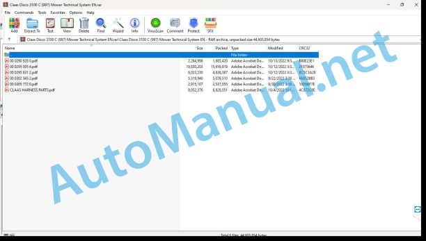
File List:
00 0290 928 0.pdf
00 0295 005 4.pdf
00 0295 831 2.pdf
00 0302 565 2.pdf
00 0305 772 0.pdf
CLAAS HARNESS PARTS.pdf
00 0290 928 0.pdf:
DISCO 3100 C, RC
Table of contents
Introduction
Validity of manual
Overview
CCN explanation
CCN (CLAAS Component Number)
Electric systems standard
Overview
Hydraulic system standard
Overview
CCN (CLAAS Component Number)
09 Hydraulic system
0920 Valves
Components
Working / transport position hydraulic cylinder (3169)
One-way restrictor valve, one-sided (7060)
0980 Hydraulic circuit diagram
Hydraulic circuit diagram DISCO 3100 C, RC
Description of function
00 0295 005 4.pdf:
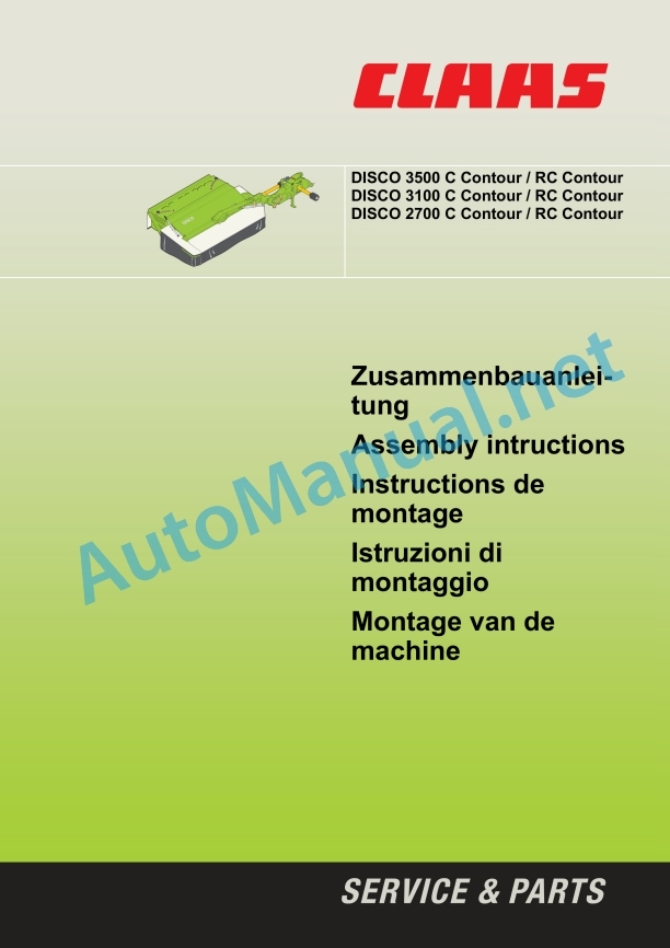
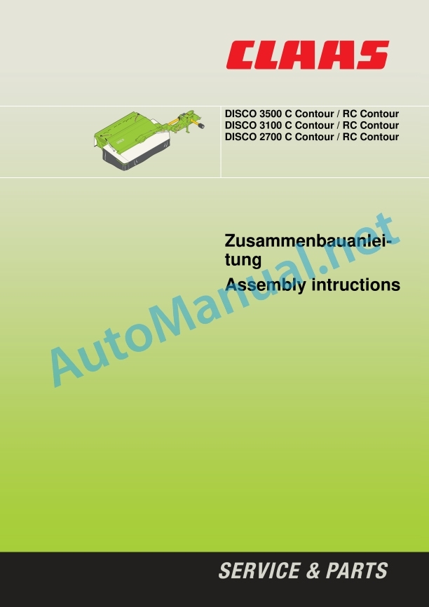
Zusammenbauanleitung
1 Einleitung
Einleitung
3 Allgemeine Hinweise
Be sure to be stranded
Kennzeichnung von Warn- und Gefahrenhinweisen
Bestimmungsgemäße Verwendung
Safety precautions wi warning notice
Allgemne Sicherheitshinweise
4 Assembly
General information regarding installation
Construction of the Scheibenmähwerks
Work follow-up – Love on Palette
Dreipunktbock
Ausleger – Drehgelenk
Auffahrsicherung
Ausleger – Rahmen
Aufbereitergehäuse
Protective Halterungen DISCO 3500 C / 3500 RC
Safety Halterungen DISCO 3100 C / 3100 RC / 2700 C / 2700 RC
Schutztücher
Zugseile
Gelentorment
Mahklingen
Schutzbügel
After subsequent installation and for construction work and beaching!
Assembly instructions
1 Introduction
Introduction
2 Contents
3 General Information
Of special importance
Identification of warnings and dangers
Designated use
Safety decals with warning symbols
General safety instructions
4 Assembly
General instructions for assembly
Assembly of the disc mower
Sequence of operations – shipment on palettes
Three point mounting
Mower – sl joint
Bump safeguard
ower – mounting frame
Conditioner housing
Safety guard holders DISCO 3500 C / 3500 RC
Safety guard holders DISCO 3100 C / 3100 RC / 2700 C / 2700 RC
Safety guards
Pull rope
Universal drive shafts
Mowing blades
Safety frame
Check and observe after complete assembly and before putting into operation.
Assembly instructions
1 Introduction
Introduction
2 Table des matières
3 Remarques generales
A respectful imperative
Marquage des avertissements et des dangers
Utilization conforme aux prescriptions
Autocollants de sécurité avec pictogramme d’avertissement
Consignes generales de sécurité
4 Assembly
Consignes generales de montage
Assemblage de la faucheuse rotative à disques
Ordre de montage – Livraison sur palette
Support d’attelage three points
Bras – Articulation tournante
Dispositif de sécurité anti-collision
Bras – Chassis
Carter du conditio Supports the toile de protection DI C / 3500 RC
Supports the toile de protection DISCO 3100 C / 3100 RC / 2700 C / 2700 RC
Toilet de protection
Arbres à cardan
Lames de coupe
Etrier de protection
Be sure to check the installation terminé and the mise en service!
Istruzioni di montaggio
1 Introduction
Introduzione
3 Indicazioni generali
Avvertenze importanti
Simbologia concernente gli avvertimenti and gli avvisi di pericolo
Norme per il corretto impiego
Decalcomania con simboli di pericolo
Indicazioni generali per la sicurezza
4 Montaggio
Istruzioni generali per il montaggio
Assemblaggio della falciatrice a dischi
Sequenza dei lavori – Spedizione su pallet
Attacco a tre punti
Braccio – Giunto snodato
Sicurezza contro gli ostacoli
Braccio – Telaio
Scatola del condizionatore
Support of the technology DISCO 3500 C / 3500 RC
Support of the technology DISCO 31 C / 3100 RC / 2700 C / 2700 RC
Teli di protione
Cavo di traino
Alberi cardanici
Sezioni lama
Staffa di protezione
Make sure the assembly works well, control and handle the first mess in the camp!
Assembly of the machine
1 Introduction
Introduction
2 Contents
3 General instructions
What you should pay particular attention to
Indication of warnings and dangers
Use according to intended use
Safety stickers with hazard symbols
General safety instructions
4 Assembly
General notes on installation
Installing the disc cutter bar
Work order – delivery on pallet
Three-point buck
Extension – swivel joint
Drive-on protection
Outrigger – chassis
Preparation house
Screen cloth holders DISCO 3500 C / 3500 RC
Screen cloth holders DISCO 3100 C / 3100 RC / 2700 C / 2700 RC
Shielding cloths
Traction cables
Coupling shafts
Mowing blades
Shielding brackets
Check and observe after installation and before commissioning!
00 0295 831 2.pdf:
Assembly instructions
1 Introduction
Introduction
2 Contents
3 General information
Of particular note
Labeling of warnings and danger notices
Intended Use
Safety sticker with warning symbols
General safety instructions
4 assembly
General information on assembly
Assembling the disc mower
Sequence of work – delivery in crate
Three-point buck
Boom – swivel joint
Collision protection
Boom – frame
Conditioner housing
Protective cloth holders DISCO 3500 C / DISCO 3500 RC
Protective cloth holders DISCO 3100 C / 3100 RC / 2700 C / 2700 RC
protective cloths
Pull ropes
Drive shafts
mowing blades
Protective bar
Check and observe after installation and before commissioning!
Assembly instructions
1 Introduction
Introduction
2 contents
3 General information
Of special importance
Identification of warnings and dangers
Designated use
Safety decals with warning symbols
General safety instructions
4 Assembly
General instructions for assembly
Assembly of the disc mower
Sequence of operation – delivery in crates
Headstock
Mower – swivel joint
Bump safeguards
Mower – mounting frame
Conditioner housing
Safety guard holders DISCO 3500 C / DISCO 3500 RC
Safety guard holders DISCO 3100 C / 3100 RC / 2700 C / 2700 RC
Safety guards
Pull rope
Universal drive shafts
Mowing blades
Safety frame
Check and observe after complete assembly and before commissioning.
00 0302 565 2.pdf:
Sensor system
Table of contents
CCN explanation
CCN (CLAAS Component Number)
Electric system standard
Overview
Hydraulic system standard
Overview
CCN (CLAAS Component Number)
Introduction
Safety rules
Safety and hazard information
10 Electrical / Electronic equipment
1097 Testing / Measuring / Adjusting
Test report of the angle sensor (0011780.x)
Application of test report
Required tools
Test report of the angle sensor (0011780.x)
Testing / Measuring / Adjusting of angle sensor (0011780.x)
1. Reason for test
2. Mechanical test of angle sensor
3. Electric test with CDS
4. Electric test with multimeter
5. Mechanical test of connecting cable
Completing the machine
Test report of position and speed sensors
Application of test report
Required tools
Sensor variants
Part numbers of speed sensors
Part number of position sensor
Test report of position and speed sensors
Testing / measuring / adjusting of position and speed sensors
1. Reason for test
2. Mechanical test
3. Electric test with CDS
4a. Installation dimensions
Check of installation dimension
Installation dimensions of gearbox speed sensor (0011 799.x) and cam speed sensor (0011 810.x)
Installation dimension of position sensor (0011 815.x)
4b. Installation position
Centring of sensor
Metal-free zone
5. Electric test with multimeter
Voltage measurement
Direction of rotation and speed sensor (0011 605.x)
Measured values table
6. Mechanical test of connecting cable
Completing the machine
Test report of the urea sensor (00 0773 207 x)
Application of test report
Required tools
Parts number of the urea sensor
Test report of the urea sensor
Testing / measuring / adjusting urea sensor
1. Reason for test
2. Mechanical test
3. Mechanical test of connecting cable
4. Electric test with multimeter
5. Component test with the CDS
00 0305 772 0.pdf:
Table of contents
Introduction
Notes on the manual
Information about this Technical Systems Manual
Using the manual
Document structure based on subassemblies
Search and find
Directions
Identifying warnings
Hazard signs
Signal word
Safety rules
Safety signs and warnings
Requirement made on technical staff
Children in danger
Hazard areas of the machine
Instructors travelling along during fieldwork
Risk of injury from rotating shafts
Structural alterations of the machine
Optional equipment and spare parts
Control of running machine
Technical condition
Respecting technical limit values
Danger from machine parts that continue rotating
Keeping safety devices functional
Personal protective equipment
Wearing suitable clothing
Removing dirt and loose objects
Parking the machine safely
Unsuitable operating utilities
Safe handling of service fluids and auxiliary utilities
Environmental protection and disposal
Keeping the cab free of chemicals
Avoiding fires
Potentially fatal electric shock from overhead lines and lightning strike
Electric shock from electric system
Noise may damage your health
Pre-loaded machine parts
Liquids under pressure
Compressed air
Toxic exhaust gases
Hot surfaces
Safe access and leaving
Working only on the stopped machine
Hazards during repairs
Raised machine parts and loads
Danger from welding work
Checking and charging the battery
Preparations for cases of emergency
10 Electrical / Electronic equipment
1098 Fault / remedy
ISOBUS checklist for fault analysis
Use of the checklist
1. Fault when loading the graphical user interface of the ISOBUS implement
1.1 The graphical user interface for an ISOBUS implement (object pool) is not loaded to the terminal
1.2 Loading the graphical user interface of the ISOBUS implement is not finished or is interrupted
1.3 The graphical user interface for an ISOBUS implement is loaded to the wrong terminal
2. Fault when assigning function keys
2.1 No keys available for assigning, no AUX input available
2.2 Assigned function keys without a function or faulty
2.3 Assignment of function keys after restarting no longer available
3. Task management fault (TC BAS)
3.1 Meter readings from the implement not available or remain at zero
3.2 Import/export of iso.xml not possible/only partially possible
3.3 Missing reference tracks in import/export
3.4 Individual tasks cannot be deleted from the terminal
3.5 Folder structure task data on the USB stick
4. Section Control fault (TC SC)
4.1 TC SC at the wrong terminal
4.2 TC SC without a function/only with a partial function
4.3 Incorrect switching on or off of TC SC
5. Testing and measuring
5.1 Testing and measuring – terminal socket
5.2 Testing and measuring – ISOBUS socket
5.3 Testing and measuring – diagnostic socket
6. Diagnosis with CDS
6.1 ISOBUS check (load object pool)
6.2 ISOBUS CAN logging (assigning of function keys)
6.3 ISOBUS CAN logging (assigned key without a function)
6.4 ISOBUS CAN logging (assignment no longer available, gets lost)
6.5 ISOBUS CAN logging (in the event of a fault with task management)
6.6 ISOBUS CAN logging (general problems)
7. ISOBUS components/AEF compatibility/software statuses
7.1 ISOBUS components and fault description
7.2 ISOBUS functionalities
7.3 Software statuses/AEF compatibility
CLAAS HARNESS PARTS.pdf:
CLAAS HARNESS PARTS
Table of contents
10 Electrical / Electronic equipment
1081 Overview of connectors
CLAAS HARNESS PARTS (CHP)
John Deere Repair Technical Manual PDF
John Deere Repair Technical Manual PDF
John Deere Repair Technical Manual PDF
John Deere Parts Catalog PDF
John Deere Tractors 6300, 6500, and 6600 Parts Catalog CQ26564 (29SET05) Portuguese
John Deere Repair Technical Manual PDF
John Deere Repair Technical Manual PDF
John Deere Repair Technical Manual PDF
John Deere Diesel Engines POWERTECH 2.9 L Component Technical Manual CTM126 Spanish
John Deere Repair Technical Manual PDF
John Deere Repair Technical Manual PDF

