Claas Scorpion 7055 (K26) Telehandlers Repair Manual EN
$300.00
- Model: Scorpion 7055 (K26) Telehandlers
- Type Of Manual: Repair Manual
- Language: EN
- Format: PDF(s)
- Size: 370 MB
File List:
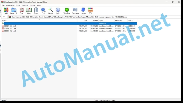
00 0298 243 4.pdf
00 0301 792 1.pdf
00 0301 992 1.pdf
00 0298 243 4.pdf:
SCORPION7044 (K24 / 416-01)7050 (K25 / 416-07)7055 (K26 / 416-03)9055 (K27/416-05)
Table of contents
Introduction
General information
Validity of manual
Using the manual
Text and figures
Document structure based on sub-assemblies
Search and find
Directions
Abbreviations
Technical terms
General repair instructions
Technical specifications
Information on technically correct repairs
Self-locking bolts
Liquid locking compound
Steel roller chains
Tensioning
Chain connector
Chain connector type E with spring
Chain connector type G with wire
Chain connector type S with cotter pins
Taper ring connections
Dismounting
Installation
Gib head key connections
Dismounting
Installation
Lock collar bearing
Dismounting
Installing
Adapter sleeve bearing
Dismounting
Installation
Chuck bushing
Removing
Dismounting of version A
Dismounting of version B
Installing
Chuck bushing version A
Chuck bushing version B
Circlips
Ferrule fittings
Screwing in
Leaky ferrule fittings
Sealing cone fittings
Hydraulic hoses
Hose routing
Treatment of sealing faces
Spare parts
Tightening torques
Tightening torques for metric ISO screw thread
Tightening torques for metric fine thread
Tightening torques for screwed pipe connections with sealing cone joint and hydraulic threaded joints with soft core seal
Tightening torques for hydraulic fittings with ferrule
Tightening torques for hydraulic male connectors SDS shape B and E
Tightening torques for hydraulic swivel screw fittings
Tightening torque for hollow screws (with copper sealing ring)
Tightening torques for hydraulic male connectors SDE shape H, with adjustable direction
Tightening torques for brake line screw fittings
Tightening torque for tubes with O-ring and union nuts
Tightening torques for worm drive hose clamps
Tightening torques for hose clamps with round pins
Tightening torques for tyres
CCN explanation
CCN (CLAAS Component Number)
Electric systems standard
Hydraulic system standard
CCN (CLAAS Component Number)
General information
Important
Identification of warning and danger signs
General safety and accident prevention regulations
First aid measures
Danger of injury from hydraulic liquid
Leaving the machine
Putting the machine out of operation
Jacking up the machine
Adjusting and maintenance work
Welding work
01 Engine
0102 Complete component
Diesel engine
Work preparation
Special tool
Technical specifications
Installation
Diesel engine
Work preparation
Special tool
Technical specifications
Installation
0125 Injection – / Fuel system
Fuel tank
Work preparation
Technical specifications
Draining the fuel
Removing the fuel level sensor
Installing the fuel level sensor
Removing
Installing
Fuel filter
Technical specifications
Without fuel pre-heater:
With fuel pre-heater:
Installation
With fuel pre-heater:
Without fuel pre-heater:
Fuel filter
Technical specifications
Without fuel pre-heater:
With fuel pre-heater:
Installation
With fuel pre-heater:
Without fuel pre-heater:
Fuel lines
Technical specifications
Fuel lines
Technical specifications
0135 Cooling system
Engine radiator
Special tool
Technical specifications
Installation
Technical specifications
Removing the fan drive hydraulic motor
Installing the fan drive hydraulic motor
Removing the fan drive valve block
Installing the fan drive valve block
Adjusting the upper fan speed
Compensating tank
Technical specifications
Installation instructions
0140 Exhaust system
Diesel particulate filter
Technical specifications
Installation
Diesel particulate filter
Technical specifications
Installation
0145 Air intake
Air filter housing
Technical specifications
Installation
Air filter housing
Technical specifications
Installation
Charge air cooler
0150 Engine attachment parts
V-belt cover
Technical specifications
Installation
V-belt cover
Technical specifications
Installation
Electric starting motor
Installation
Electric starting motor
Installation
Alternator
Installation
Alternator
Installation
0155 Engine control
Accelerator pedal
Technical specifications
Installation
02 Gearbox / Clutch / Universal drive shaft
0210 Oscillation damper
Oscillation damper
Work preparation
Technical specifications
Installation
0230 Mechanical gearbox
High-speed gearbox
Work preparation
Special tool
Technical specifications
Applies to SCORPION 7055 and 9055
Disassembly
Assembly
Installation
Applies to SCORPION 7055 and 9055
0238 Gearbox control
Timing cover
Work preparation
Special tool
Technical specifications
Disassembly
Applies to SCORPION 7044
Applies to SCORPION 7044
Applies to SCORPION 7044
Assembly
Applies to SCORPION 7044
Installation
Applies to SCORPION 7044
0260 Universal drive shaft
Universal drive shafts
Technical specifications
Installation instructions
03 Chassis
0305 Axle suspension
Hydraulic cylinder level compensation
Work preparation
Technical specifications
Installation
Hydraulic cylinder floating axle lock
Work preparation
Technical specifications
Installation
0325 Driven steering axle, front
Front steering drive axle
Special tool
Technical specifications
Installation
Front steering drive axle
Special tool
Technical specifications
Removing
Installing
Wheel hub
Work preparation
Special tool
Technical specifications
Removing the wheel hub completely
Installing the wheel hub completely
Disassembly
Assembly
Stub axle
Work preparation
Special tool
Type 26.25:
Type 26.32:
Type 26.43:
Type 26.25:
Type 26.32:
Type 26.43:
Type 26.25:
Type 26.32, type 26.43:
Technical specifications
Installing
Plug-in axles
Technical specifications
Installation
Track rods
Technical specifications
Track rods
Technical specifications
Axle body
Work preparation
Special tool
Type 26.32:
Type 26.43:
Type 26.32:
Type 26.43:
Technical specifications
Removing
Installing
Differential
Work preparation
Special tool
Technical specifications
Removing the drive flange
Installing the drive flange
Disassembly
Assembly
If the measured rolling moment equals the specified rolling moment value (b), skip this work step!
Installation
Checking the backlash
Differential
Work preparation
Special tool
Technical specifications
Removing the drive flange
Installing the drive flange
Disassembly
Assembly
If the measured rolling moment equals the specified rolling moment value (b), skip this work step!
Installation
Checking the backlash
Differential lock
Work preparation
Technical specifications
Installation
Differential
Technical specifications
Work preparation
Special tool
Type 26.32:
Type 26.43:
Removing
Installing
0330 Driven steering axle, rear
Rear drive axle
Special tool
Technical specifications
Installation
Rear steering drive axle
Technical specifications
Removing
Installing
Wheel hub
Stub axle
Plug-in axles
Track rods
Axle body
Differential
Differential
Technical specifications
Work preparation
Special tool
Type 26.32:
Type 26.43:
Removing
Installing
0335 Ground drive
Ground drive hydraulic pump
Technical specifications
Installation
Additional ground drive hydraulics variable-displacement motor
Technical specifications
Installation
04 Brake
0405 Service brake
Service brake
Bleeding
Front axle
Rear axle
Brake mechanism
Work preparation
Special tool
Technical specifications
Installation
Brake mechanism
Work preparation
Special tool
Technical specifications
Installation
Checking the operating clearance
Inching pedal
Technical specifications
Installation
Calibrating the inching pedal with the CDS
Calibrating the inching pedal with the CDS
Brake valve
Technical specifications
Installation
Accumulator charge valve
Technical specifications
0415 Parking brake
Parking brake
Bleeding
Deactivating
Activating
Parking brake
Bleeding
Deactivating
Activating
0420 Trailer air brake
Compressed-air accumulator
Installation
Relieving the pressure
05 Steering
0505 Steering
Steering unit
Technical specifications
Installation
Steering mode valve
Technical specifications
Installation
Steering hydraulic cylinder
Technical specifications
Disassembly
Assembly
Installation
Adjusting the steering sensors
Synchronizing the steering
Steering hydraulic cylinder
Technical specifications
Disassembly
Assembly
Installation
Adjusting the steering sensors
Synchronizing the steering
06 Lift device
0620 Telescopic arm
Telescopic arm
Special tool
Technical specifications
Installation
Removing the inner tube
Installing the inner tube
Removing the outer tube
Installing the outer tube
Slide plates
Technical specifications
Replacing
Quick-change plate
Work preparation
Special tool
Technical specifications
Applies to mechanical quick-change plate
Applies to hydraulic quick-change plate
Installing
Applies to mechanical quick-change plate
Applies to hydraulic quick-change plate
Lift hydraulic cylinder
Work preparation
Special tool
Technical specifications
Installation
Insert safety support
Compensation hydraulic cylinder
Work preparation
Special tool
Technical specifications
Installation
Push-out hydraulic cylinder
Work preparation
Special tool
Technical specifications
Installation
Tipping hydraulic cylinder
Work preparation
Special tool
Technical specifications
Removing the tube rupture safeguard
Installing the tube rupture safeguard
Installation
Quick-change lock hydraulic cylinder
Special tool
Technical specifications
Disassembly
Assembly
Load stabiliser
Technical specifications
Installation instructions
Lift arm rotary angle sensor
Technical specifications
Installation instructions
Calibrating the rotary angle sensor with the CDS
Automatic bucket return travel sensor
Technical specifications
Installation
Calibrating the travel sensor with the CDS
07 Hitch
0705 Coupling frame
Trailer hitch
Technical specifications
Height-adjustable trailer hitch
Technical specifications
0720 Hitch
Work preparation
Technical specifications
Removing
Installing
Removing the pin
Installing the pin
Removing the sensor plate
Installing the sensor plate
09 Hydraulic system
0900 Hydraulic system – General
Hydraulic system – General
Special tool
Filling the accumulator
0905 Hydraulic oil tank
Hydraulic oil tank
Special tool
Technical specifications
Installation
Generating a vacuum
0907 Hydraulic oil cooler
Hydraulic oil cooler
0910 Pumps
Hydraulic tandem pump
Technical specifications
Installation
Working hydraulics pump
Technical specifications
Removing
Installing
0915 Hydraulic lines
Pressure accumulator, load stabiliser
Technical specifications
Installation instructions
0920 Valves
Working hydraulics valve block
Work preparation
Technical specifications
Installation
10 Electrical / Electronic equipment
1000 General electrical system
Electric system – General
Special tool
1005 Power supply
Technical specifications
Installation instructions
Battery isolating switch
1010 Central electrics
Central terminal compartment
Technical specifications
Installation
Steering electronics
Technical specifications
Installation
Technical specifications
Removing the working hydraulics electronics
Installing the working hydraulics electronics
Removing the electronics option
Installing the electronics option
Removing the cab electronics
Installing the cab electronics
Load sensor
Work preparation
Technical specifications
Installation
1020 Driving lights
Headlights / taillights
Technical specifications
1025 Working lights
Worklights
Technical specifications
1035 Operation / Multifunction control lever
Control lever electronics
Technical specifications
Installation
Left instrument panel
Technical specifications
Installation
Right instrument panel
Technical specifications
Installation
Display instruments on right A-pillar
Technical specifications
Installation
Overload warning display
Right switch panel
Technical specifications
Removing switches
Installing switches
Creep gear potentiometer
Technical specifications
Installation
Calibrating the potentiometer with the CDS
12 Cab / Operator’s platform
1210 Cab
Technical specifications
Installation
Special tool
Technical specifications
1230 Seat
Driver’s seat
Technical specifications
Installation
1235 Cab heater
Cab heater lines
Special tool
Technical specifications
Heat exchanger
Special tool
Technical specifications
Installation
Technical specifications
Installation
1240 Air condition
Air conditioning system – General information
Draining the air conditioner
Filling the air conditioner
Air conditioner compressor
Technical specifications
Installation
Evaporator
Technical specifications
nstallation
Condenser and filter receiver drier
Technical specifications
Removing the condenser
Installing the condenser
Removing the filter receiver drier
Installing the filter receiver drier
75 Central lubrication system
7505 Reservoir / Pump
Tank, pump
Technical specifications
Installation
Adjustment
7515 Lubrication system / Lines
Lubrication lines
Special tool
80 Various components / Machine body
8025 Panellings / Hoods
Engine bonnet
Technical specifications
Installation
Technical specifications
Installation
Underriding protector
Technical specifications
Installation
Cab front covering
Technical specifications
Installation
8030 Mud guards
Mud guard
Technical specifications
95 Maintenance parts overview
9599 Maintenance jobs
Maintenance access
Replacing the fuel sediment filter
Bleeding the fuel system
Deutz TCD 3.6 L4:
Deutz TCD 4.1 L4:
Adjusting the valve lash
Deutz TCD 3.6 L4:
Deutz TCD 4.1 L4:
Checking the brake discs for wear
Tensioning the V-belt in the alternator
Tensioning the V-belt in the air compressor
Tensioning the V-belt in the air conditioner compressor
Checking the high-speed gearbox oil level
Draining oil from the high-speed gearbox
Topping up oil in the high-speed gearbox
Checking the 4-wheel drive shut-down gearbox oil level
Draining the 4-wheel drive shut-down gearbox oil
Top up the 4-wheel drive shut-off gearbox oil
Checking the planetary gear oil level
Draining the planetary gear oil
Topping up planetary gear oil
Checking the differential oil level
Draining the differential oil
Topping up differential oil
Checking the telescopic arm slide plates
Checking the hydraulic system oil level
Changing the hydraulic system oil
Replacing the hydraulic system return filter
Changing the hydraulic system fresh air filter element
Replacing the hydraulic system suction filter
Changing the charge pressure filter for the hydraulic system
Cleaning the line filter for the control unit inlet in the hydraulic system
Cleaning the line filter for the control unit line in the hydraulic system
Service indicator
00 0301 792 1.pdf:
Deutz TCD 4.1 L4
Table of contents
Introduction
General information
Validity of manual
Using the manual
Text and figures
Document structure based on sub-assemblies
Search and find
Directions
Abbreviations
Technical terms
General repair instructions
Technical specifications
Information on technically correct repairs
Self-locking bolts
Liquid locking compound
Steel roller chains
Tensioning
Chain connector
Chain connector type E with spring
Chain connector type G with wire
Chain connector type S with cotter pins
Taper ring connections
Dismounting
Installation
Gib head key connections
Dismounting
Installation
Lock collar bearing
Dismounting
Installing
Adapter sleeve bearing
Dismounting
Installation
Chuck bushing
Removing
Dismounting of version A
Dismounting of version B
Installing
Chuck bushing version A
Chuck bushing version B
Circlips
Ferrule fittings
Screwing in
Leaky ferrule fittings
Sealing cone fittings
Hydraulic hoses
Hose routing
Treatment of sealing faces
Spare parts
Operating materials
Tightening torques
Tightening torques for metric ISO screw thread
Tightening torques for metric fine thread
Tightening torques for hydraulic fittings with ferrule
Tightening torques for screwed pipe connections with sealing cone joint and hydraulic threaded joints with soft core seal
Tightening torques for hydraulic male connectors SDS shape B and E
Tightening torques for hydraulic male connectors SDE shape H, with adjustable direction
Tightening torques for hydraulic swivel screw fittings
Tightening torque for hollow screws (with copper sealing ring)
Tightening torques for brake line screw fittings
Tightening torque for tubes with O-ring and union nuts
Tightening torques for worm drive hose clamps
Tightening torques for hose clamps with round pins
CCN explanation
CCN (CLAAS Component Number)
Electric systems standard
Hydraulic system standard
CCN (CLAAS Component Number)
General information
Important
Signal word
General safety and accident prevention regulations
First aid measures
Danger of injury from hydraulic liquid
Leaving the machine
Putting the machine out of operation
Jacking up the machine
Adjusting and maintenance work
Welding work
Instructions for work on the diesel engine
Accident protection
Cleanliness
Installation instructions
Engine overhaul
01 Engine
0102 Complete component
Engine data
TCD 4.1 L4
Engine description
Ignition order
Cranking the engine
Special tool
Installing the cranking tool on the flywheel side
Installing the cranking tool on the torsional vibration damper
0105 Engine suspension
Engine suspension
Technical specifications
0110 Engine housing
Crankcase venting
Technical specifications
Installation
Crankshaft speed sensor
Technical specifications
Work preparation
Camshaft speed sensor
Technical specifications
Flywheel housing
Technical specifications
Special tool
Installation
Gearwheel housing
Technical specifications
Work preparation
Installation
Crankshaft seal
Technical specifications
Special tool
Removing
Installing
Front cover
Technical specifications
Installation
Crankshaft seal
Technical specifications
Special tool
Removing
Installing
Replacing the shaft sleeve
Oil sump
Technical specifications
Work preparation
Special tool
Installation
Crankcase
Technical specifications
Work preparation
Checking the cylinder bore
0115 Engine unit
Technical specifications
Special tool
Installation instructions
Checking the piston
Removing the piston rings
Installing the piston rings
Checking the piston rings
Measuring the piston excess height
Connecting rod
Technical specifications
Special tool
Installation instructions
Removing
Installing
Checking
Torsional vibration damper
Technical specifications
Work preparation
Special tool
Installation
Crankshaft
Technical specifications
Removing
Installing
Checking the axial play
Crankshaft bearing
Technical specifications
Special tool
Installation
Flywheel
Technical specifications
Work preparation
Special tool
Installation
Removing the ring gear
Installing the ring gear
0120 Cylinder head / Valves / Idler gear
Valve cover
Technical specifications
Installation
Cylinder head
Technical specifications
Special tool
Removing
Installing
Rocker lever
Technical specifications
Disassembly
Assembly
Installation
Camshaft
Technical specifications
Installation
Checking
Technical specifications
Special tool
Removing
Installing
Checking
Valve plate and valve shaft diameter
Diameter of valve guides
Valve shaft play
Valve depth
Adjusting the valve lash
Combustion pressure
Special tool
Checking
0125 Injection – / Fuel system
Fuel lift pump
Technical specifications
Fuel filter
Technical specifications
Fuel lines
Technical specifications
Special tool
Installation
Technical specifications
Work preparation
Special tool
Removing the rail / fuel pressure sensor
Removing the pressure relief valve
Installing the pressure relief valve
Installing the rail / fuel pressure sensor
Installation
Injector
Technical specifications
Special tool
Installation instructions
Removing
Installing
Injector sleeve
Technical specifications
Work preparation
Special tool
Removing
Installation
High-pressure pumps
Technical specifications
Work preparation
Special tool
Installation
Control block
Technical specifications
Work preparation
Removing
Disassembly
Assembly
Installing
0130 Lubricating oil system
Oil suction tube
Technical specifications
Lubrication oil cooler
Technical specifications
Work preparation
Lubricating oil cooler housing
Technical specifications
Installation
Lubrication pump
Oil spray nozzle
Technical specifications
Installation instructions
Oil level dipstick
Technical specifications
0135 Cooling system
Coolant lines
Technical specifications
Work preparation
Thermostat housing
Technical specifications
Work preparation
Installation
Thermostat
Technical specifications
Installation
Checking the stroke
Engine temperature sensor
Technical specifications
Coolant pump
Technical specifications
Work preparation
Installation
Fan bearing
Technical specifications
0140 Exhaust system
Turbocharger
Technical specifications
Work preparation
Special tool
Installation
Main exhaust manifold
Technical specifications
Work preparation
Special tool
Installation
Exhaust recirculation cooler
Technical specifications
Work preparation
Special tool
Installation
Reed valve
Technical specifications
Work preparation
Installation
Actuator
Technical specifications
Work preparation
Special tool
Installation instructions
Installation
Exhaust gas mass flow sensor
Technical specifications
Installation instructions
0145 Air intake
Charge air tube
Technical specifications
Work preparation
Installation
Heater flange
Technical specifications
Work preparation
Disassembly
Assembly
Installation
Mixing tube
Technical specifications
Installation
Orifice plate
Technical specifications
Installation
0150 Engine attachment parts
Electric starting motor
Technical specifications
Installation instructions
Alternator
Technical specifications
Disassembly
Assembly
Installation
Removing the support
Installing the support
Technical specifications
Air conditioner compressor
Technical specifications
Installation instructions
Belt tensioner
Technical specifications
Drive belt pulley
Technical specifications
Air compressor
Technical specifications
Work preparation
Installation instructions
0155 Engine control
Starting high-current relay
Technical specifications
0165 Exhaust gas aftertreatment
Diesel particulate filter
Technical specifications
Work preparation
Special tool
Disassembly
Assembly
Diesel particulate filter differential pressure sensor
Technical specifications
00 0301 992 1.pdf:
SCORPION7044 (K24 / 416-11)7050 (K25 / 416-17)7055 (K26 / 416-13)9055 (K27 / 416-15)
Table of contents
Introduction
General information
Validity of manual
Using the manual
Text and figures
Document structure based on sub-assemblies
Search and find
Directions
Abbreviations
Technical terms
General repair instructions
Technical specifications
Information on technically correct repairs
Self-locking bolts
Liquid locking compound
Steel roller chains
Tensioning
Chain connector
Chain connector type E with spring
Chain connector type G with wire
Chain connector type S with cotter pins
Taper ring connections
Dismounting
Installation
Gib head key connections
Dismounting
Installation
Lock collar bearing
Dismounting
Installing
Adapter sleeve bearing
Dismounting
Installation
Chuck bushing
Removing
Dismounting of version A
Dismounting of version B
Installing
Chuck bushing version A
Chuck bushing version B
Circlips
Ferrule fittings
Screwing in
Leaky ferrule fittings
Sealing cone fittings
Hydraulic hoses
Hose routing
Treatment of sealing faces
Spare parts
Tightening torques
Tightening torques for metric ISO screw thread
Tightening torques for metric fine thread
Tightening torques for screwed pipe connections with sealing cone joint and hydraulic threaded joints with soft core seal
Tightening torques for hydraulic fittings with ferrule
Tightening torques for hydraulic male connectors SDS shape B and E
Tightening torques for hydraulic swivel screw fittings
Tightening torque for hollow screws (with copper sealing ring)
Tightening torques for hydraulic male connectors SDE shape H, with adjustable direction
Tightening torques for brake line screw fittings
Tightening torque for tubes with O-ring and union nuts
Tightening torques for worm drive hose clamps
Tightening torques for hose clamps with round pins
Tightening torques for tyres
CCN explanation
CCN (CLAAS Component Number)
Electric systems standard
Hydraulic system standard
CCN (CLAAS Component Number)
General information
Important
Identification of warning and danger signs
General safety and accident prevention regulations
First aid measures
Danger of injury from hydraulic liquid
Leaving the machine
Putting the machine out of operation
Jacking up the machine
Adjusting and maintenance work
Welding work
01 Engine
0102 Complete component
Diesel engine
Work preparation
Special tool
Technical specifications
Installation
Diesel engine
Work preparation
Special tool
Technical specifications
Removing
With compressed-air brake system:
Installing
With compressed-air brake system:
0125 Injection – / Fuel system
Fuel tank
Work preparation
Technical specifications
Draining the fuel
Removing the fuel level sensor
Installing the fuel level sensor
Removing
Installing
Fuel filter
Technical specifications
Without fuel pre-heater:
With fuel pre-heater:
Installation
With fuel pre-heater:
Without fuel pre-heater:
Fuel filter
Technical specifications
Without fuel pre-heater:
With fuel pre-heate
John Deere Repair Technical Manual PDF
John Deere Repair Technical Manual PDF
John Deere Repair Technical Manual PDF
John Deere PowerTech M 10.5 L and 12.5 L Diesel Engines COMPONENT TECHNICAL MANUAL CTM100 10MAY11
John Deere Repair Technical Manual PDF
John Deere Repair Technical Manual PDF
John Deere 18-Speed PST Repair Manual Component Technical Manual CTM168 10DEC07
John Deere Repair Technical Manual PDF
John Deere Repair Technical Manual PDF
John Deere Repair Technical Manual PDF
John Deere Repair Technical Manual PDF
John Deere Repair Technical Manual PDF
John Deere Transmission Control Unit Component Technical Manual CTM157 15JUL05


