Claas Atos 350 – 330 Stage Iiib T2 (A99) Tractors Technical System EN
$300.00
- Model: Atos 350 – 330 Stage Iiib T2 (A99) Tractors
- Type Of Manual: Technical System
- Language: EN
- Format: PDF(s)
- Size: 58.9 MB
File List:
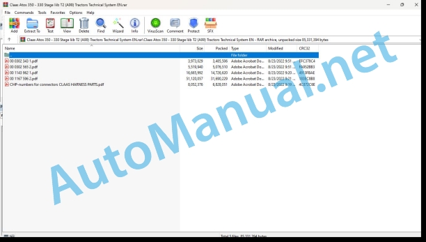
00 0302 343 1.pdf
00 0302 565 2.pdf
00 1143 962 1.pdf
00 1167 596 2.pdf
CHP-numbers for connectors CLAAS HARNESS PARTS.pdf
00 0302 343 1.pdf:
PROFI CAM 3
Table of contents
General information
Marking of warnings and hazard prevention notes
First-aid measures
CCN explanation
CCN (CLAAS Component Number)
Electric system standard
Overview
Hydraulic system standard
Overview
CCN (CLAAS Component Number)
10 Electrical / Electronic equipment
1030 Board computer / Indicators
Camera system
Description of function
1097 Testing / Measuring / Adjusting
Testing / measuring / adjusting the PROFI CAM
Checking the fuse in the video channel select box (C102)
Testing the video camera connector (C055)
1098 Fault / remedy
Fault / remedy PROFI CAM
The video monitor (C101) shows no image or cannot be switched on (indicator light fails to light up)
Video monitor (C102) displays a blue image either permanently or temporarily
The video monitor image is blurred
Replacing the fuse in the video channel select box (C102)
Connection and connecting cable with video camera (C055)
00 0302 565 2.pdf:
Sensor system
Table of contents
CCN explanation
CCN (CLAAS Component Number)
Electric system standard
Overview
Hydraulic system standard
Overview
CCN (CLAAS Component Number)
Introduction
Safety rules
Safety and hazard information
10 Electrical / Electronic equipment
1097 Testing / Measuring / Adjusting
Test report of the angle sensor (0011780.x)
Application of test report
Required tools
Test report of the angle sensor (0011780.x)
Testing / Measuring / Adjusting of angle sensor (0011780.x)
1. Reason for test
2. Mechanical test of angle sensor
3. Electric test with CDS
4. Electric test with multimeter
5. Mechanical test of connecting cable
Completing the machine
Test report of position and speed sensors
Application of test report
Required tools
Sensor variants
Part numbers of speed sensors
Part number of position sensor
Test report of position and speed sensors
Testing / measuring / adjusting of position and speed sensors
1. Reason for test
2. Mechanical test
3. Electric test with CDS
4a. Installation dimensions
Check of installation dimension
Installation dimensions of gearbox speed sensor (0011 799.x) and cam speed sensor (0011 810.x)
Installation dimension of position sensor (0011 815.x)
4b. Installation position
Centring of sensor
Metal-free zone
5. Electric test with multimeter
Voltage measurement
Direction of rotation and speed sensor (0011 605.x)
Measured values table
6. Mechanical test of connecting cable
Completing the machine
Test report of the urea sensor (00 0773 207 x)
Application of test report
Required tools
Parts number of the urea sensor
Test report of the urea sensor
Testing / measuring / adjusting urea sensor
1. Reason for test
2. Mechanical test
3. Mechanical test of connecting cable
4. Electric test with multimeter
5. Component test with the CDS
00 1143 962 1.pdf:
FL – FLC – FLE loaders
Table of contents
CCN explanation
CCN (CLAAS Component Number)
Electric system standard
Overview
Hydraulic system standard
Overview
CCN (CLAAS Component Number)
Introduction
General information
Using this diagnostic manual
Safety rules
Safety instructions and risk information
Validity of manual
Validity of this diagnostic manual
06 Lift device
0615 Front loader
Reminder
Control valve slide valves
Lifting circuit
“Shock Eliminator System” (Option)
Loading circuit
Loading circuit of FL loaders
Loading circuit of – FLE loaders
Parallelogram hydraulic circuit
Hydraulic parallelogram – “PCH System”
3rd function circuit
Loading retarder
4th function circuit
Safety system circuit
“ACS” circuit
“SCS” circuit
“Fast-Lock System” circuit
“Speed-Link System” circuit
Mechanical part
0698 Problems / remedy
Faults on the Mach System
Appearance of oil leaks
Faults on Flexpilot System
Open centre: Hydraulic malfunction noted on the tractor
Open centre: Loader does not lift the load stated
Load sensing signal (LS): Hydraulic malfunction noted on the tractor
Load sensing signal: Loader does not lift the load stated
Faults on Flexpilot System
Appearance of jerking relating to the hydraulic system
Abnormally hard to move the control lever
Control valve body rupturing underure as soon as the vehicle is first switched on
Response time too long
Appearance of oil leaks outside the control valve
Loader lowering by itself
Faults on loading circuit
Loader dumping by itself
Lack of power when digging or unloading
Checking the loader solenoid valves
Characteristics of the solenoid valves
Solenoid valve not working
Dismantling the solenoid valve
Dismantling the solenoid valve of the 3rd function on the FL loader
User advice in order to avoid clogging the solenoid valves
10 Electrical / Electronic equipment
1015 Wiring harnesses
Overview of the FL loader wiring harnesses
Wiring harness for loader equipped with 3rd function
Wiring harness for loader equipped with 3rd function and 4th function
Wiring harness for loader equipped with 3rd function, 4th function, ACS and “Fast-Lock” or “Speed-Link”
Wiring harness for loader equipped with 3rd function, 4th functioACS and “Fast-Lock” or “Speed-Link”
Wiring harness for safety loader on the lifting and loading circuit
Overview of the FLC loader wiring Wiring harness for loader equipped with 3rd function
Wiring harness for loader equipped with 3rd function and 4th function
Wiring harness for loader equipped with 3rd function, 4th function, and “Fast-Lock”
Wiring harness for loader equipped with safety function on lifting and loading
Overview of FLE loader wiring harnesses
Wiring harness for loader equipped with 3rd function
Wiring harness for loader equipped with safety function on lifting and loading
Position of components
Hydraulic system
3000 Hydraulic cylinders
5000 Accumulators
8000 Couplings – Connections
Electric system
V Electronic components
X Connections
Y Electromagnetic coil
00 1167 596 2.pdf:
ATOS 0-220
Table of contents
CCN explanation
CCN (CLAAS Component Number)
Electric system standard
Overview
Hydraulic system standard
Overview
Introduction
Validity of manual
Validity of this diagnostic manual
CCN (CLAAS Component Number)
CCN Index
01 Engine
0125 Injection – / Fuel system
Fuel supply circuit
Table of measurement values
Description of the function
Fuel supply circuit hydraulic diagram
Fuel injection circuit
Table of measurement values
Description of the function
Fuel injection circuit hydraulic diagram
0130 Lubricating oil system
Engine lubrication circuit
Table of measurement values
Description of the function
0135 Cooling system
Engine cooling circuit
Table of measurement values
Description of the function
Hydraulic diagram of the cooling circuit
0140 Exhaust system
Engine exhaust circuit
Table of measurement values
Description of the function
Diagram of the exhaust gases and recycled exhaust gases circuit
0145 Air intake
Engine air intake circuit
Table of measurement values
Description of the function
Air intake circuit diagram
0150 Engine attachment parts
Starting the engine
Table of measurement values
Description of the function
Schematic diagram of the starting circuit
Engine charging circuit
Table of measurement values
Description of the function
Charging circuit principle diagram
0155 Engine control
Engine speed setpoint
Table of measurement values
Description of the function
0165 Exhaust gas aftertreatment
Engine post-treatment system
Description of the function
0197 Test / Measurement / Setting
Checking the fuel supply pressure
Checking the engine lubrication pressure
Checking the engine thermostat
Calibrating the EGR valve
Checking the turbocharging pressure
Checking the charging circuit
Checking the alternator charging voltage
Checking the alternator charging current
02 Gearbox / Clutch / Universal drive shaft
0202 Complete component
Transmission kinematics
Transmission type
0222 Hydraulical reverser
REVERSHIFT hydraulic reverser
Table of measurement values
Description of the function
REVERSHIFT kinematics
Hydraulic reverser kinematics
Actuation hydraulic circuit
Hydraulic drainage circuit
0234 Powershift gearbox
TRISHIFT
Table of measurement values
Description of the function
TWINSHIFT
Table of measurement values
Description of the function
0242 Differential
Differential lock
Table of measurement values
Description of the function
Functional logic
Hydraulic actuation circuit
0252 Electro-hydraulical front axle drive
Four-wheel drive
Table of measurement values
Description of the function
Functional logic
Hydraulic actuation circuit
0297 Inspecting / Measuring / Setting
Calibration of the REVERSHIFT
Checking REVERSHIFT actuation
Checking the accumulator 5015
Reverser lubrication pressure check
Checking the actuation of the TRISHIFT
Calibration of the TRISHIFT
Checking the actuation of the TWINSHIFT
Checking actuation of the differential
Checking actuation of the four-wheel drive
03 Chassis
0325 Driven steering axle, front
0397 Test/Measurement/Setting
04 Brake
0405 Service brake
Service brake
Service brake without trailer braking
Service brake with trailer braking
Table of measurement values
Description of the function
Diagram of service brakes without trailer braking
Diagram of service brakes with trailer braking
Service brakes functional logic
0420 Trailer air brake
Trailer air brake
Trailer air brake
Position of trailer air brake parts
Table of measurement values
Description of the function
Checking the immobilisation of the load towed by the tractor
0425 Trailer hydraulic brake
Trailer hydraulic brake
Table of measurement values
Description of the function
Hydraulic trailer braking system control unit
Hydraulic trailer braking system control unit functional logic
Trailer hydraulic brake functional logic
0497 Test / Measurement / Setting
Checking the trailer air brake circuit
Checking the air brake circuit filling time
Checking the compressor oil consumption
Checking pressure relief valve 7907
Checking the pressure controller activation and deactivation pressure inside the air dryer
Adjusting the pressure controller inside the air dryer
Checking the drop in pressure for regeneration of the air dryer
Adjusting the return limiter valve for the air dryer
Air dryer heating resistor R046
Checking the pressure on the coupler head supply (red) 8900
Checking the main control valve for the trailer air brake
Graph of the change in main control valve pressure
Checking the relay valve
05 Steering
0505 Steering
Main steering, standard steering
Table of measurement values
Description of the function
Steering unit
Dynamic steering
Table of measurement values
Description of the function
Dynamic steering functional logic
Steering unit
0597 Testing / measuring / adjusting
Checking the pressure in the steering cylinder 3023
06 Lift device
0605 Rear power lift
ATOS 240-220 mechanical rear linkage
Description of the operation
ATOS 350-330 mechanical rear linkage
Description of the operation
Electronic rear linkage
Table of measurement values
Description of the operation
Calibrating the rear linkage
0610 Front power lift
Front linkage
Description of the function
08 Drives
0802 Rear PTO
Rear power take-off on a tractor with mechanical linkage and external controls
Table of measurement values
Description of the function
Rear power take-off, tractor with electronic linkage
Table of measurement values
Description of the function
Rear power take-off speeds
Selecting speeds
540 rpm and 1000 rpm speeds
Economy speed
Drive-proportional power take-off
Rear power take-off clutch
Checking the rear power take-off engagement pressure
0804 Front PTO
Front power take-off, tractor with mechanical linkage
Table of measurement values
Description of the function
Front power take-off of the tractor with electronic linkage
Table of measurement values
Description of the function
0897 Inspecting / Measuring / Setting
09 Hydraulic system
0910 Pumps
Steering hydraulic pump 2018
Auxiliary hydraulic system pump (2027.1)
Auxiliary hydraulic system pump (2027.2)
Reverser housing drain pump 2106
0915 Hydraulic lines
Lubrication circuit
Lubrication points
0920 Valves
Pressure limiter unit
Solenoid valve block
60 L ECO circuit actuation unit
Table of measurement values
Description of the function
90 litre circuit actuation unit
Table of measurement values
Description of the function
Auxiliary hydraulic control valves
Auxiliary hydraulic control valve, 2-way, 3 positions
Auxiliary hydraulic control valve, 4-way, 3 positions
Auxiliary hydraulic control valve, 4-way, 4 positions
Auxiliary hydraulic control valve, 6-way, 4 positions
Auxiliary hydraulic control valve, 6-way, 4 positions
Auxiliary hydraulic control valve, 6-way, 3 and 4 positions
Electro-control valve block
Table of measurement values
0935 Hydraulic system control / monitoring
Monitoring the hydraulic system
Tractor with mechanical linkage
Tractor with electronic linkage
Table of measurement values
0980 Hydraulic circuit diagrams
Hydraulic circuit on ATOS 340 two-wheel drive with mechanical reverser
Hydraulic circuit on ATOS 340-330 two-wheel drive with REVERSHIFT
Hydraulic circuit on ATOS 340-330 four-wheel drive with TWINSHIFT mechanical reverser and front power take-off
ATOS 350-330 with auxiliary hydraulic circuit on a tractor with mechanical linkage and a hydraulic control valve
Auxiliary hydraulic circuit on ATOS 240-220 with mechanical linkage and one hydraulic control valve
Auxiliary hydraulic circuit (60 litre ECO) on ATOS 240-220 with hydraulic braking, electronic linkage, 3 hydraulic control valves and one electrohydraulic control valve.
Hydraulic circuit on ATOS 230 two-wheel drive with mechanical reverser
Hydraulic circuit on ATOS 230 two-wheel drive with REVERSHIFT
Hydraulic circuit on ATOS 240-220 four-wheel drive with mechanical reverser and TWINSHIFT
Hydraulic circuit on ATOS 240-220 four-wheel drive with REVERSHIFT, TWINSHIFT and front power take-off
Hydraulic circuit on ATOS 240-220 with dynamic steering, four-wheel drive, REVERSHIFT, TRISHIFT and front power take-off
Auxiliary hydraulic circuit on ATOS 240-220 with mechanical linkage, two hydraulic control valves and hydraulic trailer brake
0997 Inspecting / Measuring / Setting
Checking the steering hydraulic pump 2018
Checking the auxiliary hydraulic system pump 2027.1
Checking the auxiliary hydraulic system pump 2027.2
Checking the reverser housing drain pump 2106
Checking the actuation pressure
Checking the auxiliary hydraulic control valve flow rate
Checking the electro-hydraulic control valve
Checking the pressure limiter 7006
10 Electrical / Electronic equipment
1005 Power supply
Supply (+30) and earth (-31)
1010 Central electrics
Fuse and relay locations
Relay and battery tray fuses
Allocation of fuses
Allocation of relays
Dashboard relay
Allocation of relays
Upper cab relay
Allocation of relays
Starting relay
Allocation of relays
Fuse and relay board (mechanical linkage)
Allocation of fuses
Relay allocation
Fuse and relay board (electronic linkage)
Allocation of fuses
Relay allocation
1012 Modules / sensors
Identification of architectures
Module A015
Description
Module input/output
Module A015
Identification
Description
Module input/output
Module A015
Identification
Description
Module input/output
Module A057
Identification
Description
Module input/output
Module A057
Identification
Description
Module input/output
Module A060
Description
Module input/output
Module A062
Description
Module input/output
Module A101
Identification
Description
Module input/output
Module A101
Identification
Description
Module input/output
Module A147 <- Rear linkage control panel )>
Description
Module input/output
Module A174
Identification
Description
Module input/output
Module A174
Identification
Description
Module input/output
1015 Wiring harnesses
Harnesses
WL001 Windscreen wiper wiring harness with fixed windscreen
List of components
List of connectors
WL002 External functions module wiring harness
List of components
List of connectors
WL002a ISO socket wiring harness
List of components
List of connectors
WL003 Cab roof wiring harness
List of components
List of connectors
WL004 Cab roof work lights wiring harness
List of components
List of connectors
WL005 Warning beacon wiring harness
List of components
List of connectors
WL006a Wiring harness for the work lights on the handrail
List of components
List of connectors
WL006b Wiring harness for the work lights on the handrail
List of components
List of connectors
WL007a Wiring harness for the front power take-off solenoid valve
List of components
List of connectors
WL007b Wiring harness for the trailer hydraulic brake solenoid valve
List of components
List of connectors
WL008 Wiring harness for the pneumatic braking pressure switch
List of components
List of connectors
WL009a CUNA braking solenoid valve wiring harness
List of components
List of connectors
WL009b Pneumatic braking solenoid valve wiring harness
List of components
List of connectors
WL010 Auxiliary electrohydraulic control valve wiring harness
List of components
List of connectors
WL011 Windscreen wiper wiring harness with opening windscreen
List of components
List of connectors
WL012a Wiring harness for injectors (3 cylinders) – ATOS 240-220
List of components
List of connectors
WL012b Wiring harness for injectors (4 cylinders) – ATOS 350-330
List of components
List of connectors
WL015 Front wiring harness
List of components
List of connectors
WL016 Alternator wiring harness
List of components
List of connectors
WL017 Battery positive wiring harness
List of components
List of connectors
WL019 Pre-heating wiring harness
List of components
List of connectors
WL020 Cab wiring harness (tractor with mechanical reverser and electronic rear linkage)
List of components
List of connectors
WL021 Cab wiring harness (tractor with mechanical reverser and mechanical rear linkage)
List of components
List of connectors
WL022 Transmission wiring harness (tractor with mechanical reverser and electronic rear linkage)
List of components
List of connectors
WL023 Transmission wiring harness (tractor with mechanical reverser and mechanical rear linkage)
List of components
List of connectors
WL024 Console wiring harness (tractor with electronic rear linkage)
List of components
List of connectors
WL025 60-litre economy circuit wiring harness (connection for the hydraulic system control module “HYD A060”)
List of components
List of connectors
WL026 Wiring harness for the front indicator lights
List of components
List of connectors
WL028 Wiring harness for the headlights and
List of components
List of connectors
WL031 Wiring harness for the rear power take-off control (tractor with mechanical rear linkage)
List of connectors
WL032 Wiring harness for the 540/540 economy rear power take-off control
List of components
List of connectors
WL033 Cab wiring harness (tractith REVERSHIFT and electronic rear linkage)
List of components
List of connectors
WL034 Cab wiring harness (tractor with REVERSHIFT and mechanical rear linkage)
List of components
List of connectors
WL035 Transmission wiring harness (tractor with REVERSHIFT and electronic rear linkage)
List of components
List of connectors
WL036 Steering angle sensor wiring harness
List of components
List of connectors
WL038 Transmission wiring harness (tractor with hydraulic reverser and mechanical linkage)
List of components
List of connectors
WL039 Engine wiring harness
List of components
List of connectors
WL040 Dynamic steering wiring harness
List of components
List of connectors
WL042a Pneumatic braking earth
List of connectors
WL042b Seat earth
List of connectors
WL043 Pneumatic earth wiring harness
List of connectors
WL044 Trailer air braking wiring harness
List of components
List of connectors
1080 Electronic circuit diagram
Identification of architectures
SCM01 Work lighting
SCM01-01 Work lights (Architecture A – B)
List of components
List of connectors
List of wiring harnesses
SCM01-01 Work lights (Architecture C – D)
List of components
List of connectors
List of wiring harnesses
SCM02 Road indicators
SCM02-01 Road indicators (Architecture A)
List of components
List of connectors
List of wiring harnesses
SCM02-01 Road indicators (Architecture B)
List of components
List of connectors
List of wiring harnesses
SCM02-01 Road indicators (Architecture C)
List of components
List of connectors
List of wiring harnesses
SCM02-01 Road indicators (Architecture D)
List of components
List of connectors
List of wiring harnesses
SCM03 Air conditioning and ventilation
SCM03-01 Air conditioning and ventilation (Architecture A – B)
List of components
List of connectors
List of wiring harnesses
SCM03-01 Air conditioning and ventilation (Architecture C – D)
List of components
List of connectors
List of wiring harnesses
SCM04 Linkage – Power take-off
SCM04-01 Linkage (Architecture B – D)
List of components
List of connectors
List of wiring harnesses
SCM04-02 Sensors and solenoid valves (Architecture B – D)
List of components
List of connectors
List of wiring harnesses
SCM04-03 Power take-off (Architecture A)
List of components
List of connectors
List of wiring harnesses
SCM04-03 Power take-off (Architecture B)
List of components
List of connectors
List of wiring harnesses
SCM04-03 Power take-off (Architecture C)
List of components
List of connectors
List of wiring harnesses
SCM04-03 Power take-off (Architecture D)
List of components
List of connectors
List of wiring harnesses
SCM05 Starting and charging circuit
SCM05-01 Preheating (Architecture A)
List of components
List of connectors
List of wiring harnesses
SCM05-01 Preheating (Architecture B)
List of components
List of connectors
List of wiring harnesses
SCM05-01 Preheating (Architecture C)
List of components
List of connectors
List of wiring harnesses
SCM05-01 Preheating (Architecture D)
List of components
List of connectors
List of wiring harnesses
SCM05-02 Starting (Architecture A)
List of components
List of connectors
List of wiring harnesses
SCM05-02 Starting (Architecture B)
List of components
List of connectors
List of wiring harnesses
SCM05-02 Starting (Architecture C)
List of components
List of connectors
List of wiring harnesses
SCM05-02 Starting (Architecture D)
List of components
List of connectors
List of wiring harnesses
SCM06 Transmission
SCM06-01 Transmission (Architecture A)
List of components
List of connectors
List of wiring harnesses
SCM06-01 Transmission (Architecture B)
List of components
List of connectors
List of wiring harnesses
SCM06-01 Transmission (Architecture C)
List of components
List of connectors
List of wiring harnesses
SCM06-01 Transmission (Architecture D)
List of components
List of connectors
List of wiring harnesses
SCM06-02 60 l/min circuit (Architecture A)
List of components
List of connectors
List of wiring harnesses
SCM06-02 60 l/min circuit (Architecture B)
List of components
List of connectors
List of wiring harnesses
SCM06-02 60 l/min circuit (Architecture C)
List of components
List of connectors
List of wiring harnesses
SCM06-02 60 l/min circuit (Architecture D)
List of components
List of connectors
List of wiring harnesses
SCM07 Accessories
SCM07-01 Radio (Architecture A – B)
List of components
List of connectors
List of wiring harnesses
SCM07-01 Radio (Architecture C – D)
List of components
List of connectors
List of wiring harnesses
SCM07-02 Accessories (Architecture A)
List of components
List of connectors
List of wiring harnesses
SCM07-02 Accessories (Architecture B)
List of components
List of connectors
List of wiring harnesses
SCM07-02 Accessories (Architecture C)
List of components
List of connectors
List of wiring harnesses
SCM07-02 Accessories (Architecture D)
List of components
List of connectors
List of wiring harnesses
SCM08 Wiper/washer
SCM08-01 Wiper/washer (Architecture A – B)
List of components
List of connectors
List of wiring harnesses
SCM08-01 Wiper/washer (Architecture C – D)
List of components
List of connectors
List of wiring harnesses
SCM10 Networks
SCM10-01 Powertrain CAN bus (CAN 1) (Architecture A)
List of components
List of connectors
List of wiring harnesses
SCM10-01 Powertrain CAN bus (CAN 1) (Architecture B)
List of components
List of connectors
List of wiring harnesses
SCM10-01 Powertrain CAN bus (CAN 1) (Architecture C)
List of components
List of connectors
List of wiring harnesses
SCM10-01 Powertrain CAN bus (CAN 1) (Architecture D)
List of components
List of connectors
List of wiring harnesses
SCM10-02 Engine CAN bus (CAN 8) (Architecture A – B)
List of components
List of connectors
List of wiring harnesses
SCM10-02 Engine CAN bus (CAN 8) (Architecture C – D)
List of components
List of connectors
List of wiring harnesses
SCM11 Supply
SCM11-01 Battery isolating switch (Architecture A)
List of components
List of connectors
List of wiring harnesses
SCM11-01 Battery isolating switch (Architecture B)
List of components
List of connectors
List of wiring harnesses
SCM11-01 Battery isolating switch (Architecture C)
List of components
List of connectors
List of wiring harnesses
SCM11-01 Battery isolating switch (Architecture D)
List of components
List of connectors
List of wiring harnesses
SCM13 Braking
SCM13-01 Braking (Architecture A)
List of components
List of connectors
List of wiring harnesses
SCM13-01 Braking (Architecture B)
List of components
List of connectors
List of wiring harnesses
SCM13-01 Braking (Architecture C)
List of components
List of connectors
List of wiring harnesses
SCM13-01 Braking (Architecture D)
List of components
List of connectors
List of wiring harnesses
SCM13-02 Trailer braking (Architecture A)
List of components
List of connectors
List of wiring harnesses
SCM13-02 Trailer braking (Architecture B)
List of components
List of connectors
List of wiring harnesses
SCM13-02 Trailer braking (Architecture C)
List of components
List of connectors
List of wiring harnesses
SCM13-02 Trailer braking (Architecture D)
List of components
List of connectors
List of wiring harnesses
SCM18 Engine
SCM18-01 Engine management (Architecture A)
List of components
List of connectors
List of wiring harnesses
SCM18-01 Engine management (Architecture B)
List of components
List of connectors
List of wiring harnesses
SCM18-01 Engine management (Architecture C)
List of components
List of connectors
List of wiring harnesses
SCM18-01 Engine management (Architecture D)
List of components
List of connectors
List of wiring harnesses
SCM18-02 Engine sensors (Architecture A – B – C – D)
List of components
List of connectors
List of wiring harnesses
John Deere Parts Catalog PDF
John Deere Harvesters 8500 and 8700 Parts Catalog CPCQ24910 Spanish
John Deere Repair Technical Manual PDF
John Deere Repair Technical Manual PDF
John Deere Diesel Engines PowerTech 4.5L and 6.8L – Motor Base Technical Manual 07MAY08 Portuguese
John Deere Repair Technical Manual PDF
John Deere Repair Technical Manual PDF
John Deere Repair Technical Manual PDF
John Deere Repair Technical Manual PDF
John Deere Repair Technical Manual PDF
John Deere Repair Technical Manual PDF
John Deere Repair Technical Manual PDF
John Deere Application List Component Technical Manual CTM106819 24AUG20

