Claas Stapler (737) Baler Operator Manual ES
$50.00
- Model: Stapler (737) Baler
- Type Of Manual: Operator Manual
- Language: ES
- Format: PDF(s)
- Size: 63.3 MB
File List:
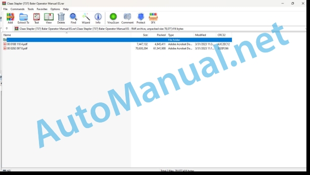
00 0188 110 4.pdf
00 0292 097 8.pdf
00 0292 097 8.pdf:
User manual
1 Regarding this instruction manual
1.1 General information
1.1.1 Application of this manual
1.1.2 Information about this instruction manual
1.1.3 Symbols and indications
1.1.4 Optional equipment
1.1.5 Qualified specialized workshop
1.1.6 Maintenance instructions
1.1.7 Information regarding warranty
1.1.8 Spare parts and technical issues
1.2 Proper application of the machine
1.2.1 Authorized use
1.2.2 Reasonably foreseeable misuse
2 Security
2.1 Recognize warning signs
2.1.1 Danger symbols
2.1.2 Keyword
2.2 Safety instructions
2.2.1 Meaning of the instruction manual
2.2.2 Observe graphic danger symbols and alarm indications
2.2.3 Requirements for all people working with the machine
2.2.4 Children in danger
2.2.5 Dangerous areas
2.2.6 Position yourself between the tractor and the machine
2.2.7 Accompanying persons
2.2.8 Couple the tractor with the machine
2.2.9 Risk of injury due to rotating shafts
2.2.10 Construction modifications
2.2.11 Optional equipment and spare parts
2.2.12 Control of the tractor in operation
2.2.13 Use only after correct start-up
2.2.14 Technical status
2.2.15 Danger due to machine breakdowns
2.2.16 Comply with technical limit values
2.2.17 Danger due to coasting parts
2.2.18 Maintain functional protection devices
2.2.19 Personal protective equipment
2.2.20 Wear appropriate clothing
2.2.21 Remove dirt and loose objects
2.2.22 Prepare the machine for road traffic
2.2.23 Dangers when driving on the road and in the countryside
2.2.24 Park the machine safely
2.2.25 Parking without supervision
2.2.26 Consumables that do not meet the requirements
2.2.27 Safe handling of consumables and auxiliary materials
2.2.28 Environmental protection and waste disposal
2.2.29 Fire protection
2.2.30 Deadly electrical discharge through overhead lines
2.2.31 Electrical shock from electrical equipment
2.2.32 Liquids under pressure
2.2.33 Pressurized air
2.2.34 Hot surfaces
2.2.35 Work only on the stopped machine
2.2.36 Maintenance work and repair work
2.2.37 Machine parts and lifted loads
2.2.38 Risks derived from welding work
2.3 Graphic danger symbols
2.3.1 Structure of graphic hazard symbols
2.3.2 Location of safety stickers
bale stacker
00 0514 612 1
00 0514 952 0
00 0516 038 0
3 Machine Description
3.1 Existing models
3.1.1 Machine Description
3.2 Overview and functions
3.2.1 Left side
3.2.2 Right side
3.3 Safety equipment
3.3.1 Signal lighting
3.3.2 Reflective equipment
3.3.3 Surety
3.3.4 Shims
3.3.5 Parking brake
3.3.6 Flywheel brake
3.3.7 Locking the pick-up
3.3.8 Locking the bale unloading ramp *
3.3.9 Fire extinguisher*
3.4 Work and service positions
3.4.1 General information
3.4.2 Top of the baler
3.5 Identification plate and serial number
3.5.1 Spare parts and technical information
3.5.2 Serial number, identification number or VIN code
3.5.3 Machine identification plate
Identification plate for machines with European approval
Identification plate for machines without European approval
Identification plate for the countries of the Customs Union (Belarus, Kazakhstan, Russia)
3.5.4 Rudder identification plate *
3.5.5 Axle identification plate
3.6 Machine information
3.6.1 Location of information stickers
bale stacker
00 0114 220 0
00 0515 152 0
3.7 General operating principle
3.7.1 Bale pressing cycle
3.8 Control terminal
3.8.1 Control terminal
3.8.2 ISOBUS connection
3.8.3 EASY on board
3.9 Transmission and drive
3.9.1 Power transmission
3.9.2 Main drive
3.9.3 Friction torque limiter
3.9.4 Freewheel cam torque limiter
3.9.5 Drive of the carrier and pick-up
3.9.6 Knotter operation
3.10 Harvest harvest
3.10.1 Pick-up
3.10.2 Short straw plate*
3.11 Power supply unit
3.11.1 Carrier
3.12 Pressing system
3.12.1 Piston and pressing channel
3.12.2 Corn kit*
3.13 Tying system
3.13.1 Tying process
3.13.2 Thread boxes
3.13.3 Thread shortage indicator
3.13.4 Needles
3.13.5 Knotters
3.13.6 Fan*
3.13.7 Turbofan*
3.14 Unloading bales
3.14.1 Road approval
3.14.2 Bale unloading ramp *
3.14.3 Bale stacker *
3.14.4 Bale ejector *
3.14.5 Bale ejector control block *
3.14.6 Humidity sensor*
3.14.7 Resetting the bale stacker sensors*
3.15 Axis
3.15.1 Single axis*
3.15.2 Wide single axis*
3.16 Service brake
3.16.1 General information
3.16.2 Pneumatic braking*
3.16.3 Hydraulic braking *
3.16.4 Active hydraulic braking *
3.17 Trailer support
3.17.1 Types of coupling
3.18 Hydraulic system
3.18.1 Hydraulic oil tank*
3.18.2 Hydraulic oil tank*
3.19 Equipment
3.19.1 Ladder
3.19.2 Working lighting*
3.19.3 Electronic module
3.19.4 12 V socket
3.19.5 Mudguards*
3.19.6 Anti-theft*
4 Control and display instruments
4.1 CEMIS 700
4.1.1 Presentation
4.1.2 Description of the menus Using the CEMIS 700
4.2 OPERATOR
4.2.1 Presentation
4.3 ISOBUS Terminal
4.3.1 Presentation
4.3.2 General information
4.4 EASY on board
4.4.1 Presentation
4.4.2 General information
5 Technical data
5.1 Baler
5.1.1 General information
5.1.2 Dimensions
Separate Baler Dimensions
Dimensions of baler with bale stacker
5.1.3 Weight
5.1.4 Weight
5.1.5 Hooking
5.1.6 Cardan shaft
5.1.7 Pick-up
5.1.8 Power group
5.1.9 Pressing system
5.1.10 Unloading bales
5.1.11 Tying device
5.1.12 Wheels
5.1.13 Braking
5.1.14 Speed - Brake Type / Axle
5.1.15 Hydraulic circuit
5.1.16 Screw tightening torques
5.1.17 Greasing and lubrication
5.1.18 Sound levels
5.2 Inputs
.bricants
5.2.2 Threads
5.3 Safety devices
5.3.1 Security screw
5.3.2 Overload safety
5.4 Tractor
5.4.1 Required power
5.4.2 Maximum authorized mass of the towing vehicle
5.4.3 PTO
5.4.4 Hooking
5.4.5 Electrical connections
5.4.6 Hydraulic connections
5.4.7 Hydraulic circuit and oil
5.4.8 Braking
6 Preparation of the machine
6.1 Turn off the machine and secure it
6.1.1 Stop and secure the tractor and machine
6.2 Adapt the tractor
6.2.1 Check the tractor power take-off protection device
6.2.2 Adapt the tractor’s pneumatic brake equipment
6.2.3 CEMIS 700* assembly
6.2.4 Assemble OPERATOR*
6.2.5 Battery cable*
6.2.6 Battery cable* – Non-ISOBUS tractor
6.3 Adapt the machine
6.3.1 Cardan shaft safety regulations
6.3.2 Cardan shaft coupling
6.3.3 Adaptation of the cardan shaft length
6.3.4 Adaptation of the cardan shaft bearing
6.3.5 Transformation kit, 8 grooves*
6.3.6 Double-joint wide-angle gimbal
6.3.7 Adaptation of the fork hitch / swing bar hitch
6.4 Hooking up the machine
6.4.1 Recommendations
6.4.2 Hitching the baler to the tractor
6.4.3 Positioning the cardan shaft
Gimbal support
Checking the steering angle
6.4.4 Connection of hydraulic hoses
Sear and pick-up
Bale ejector*
6.4.5 Connection of brake hoses
Hose identification
Hydraulic brake*
Active hydraulic brake*
Single circuit pneumatic brake*
Dual circuit pneumatic brake*
6.4.6 Connection of electrical cables
Identification of electrical cables
Standard equipment
Optional equipment
Baler power supply with ISOBUS cable
Available sockets on the power cord
Baler side
tractor side
ISOBUS adaptation kit
OPERATOR or CEMIS 700
6.4.7 Lighting connection
6.5 Pick-up
6.5.1 Important
6.5.2 Pick-up wheels*
6.5.3 Pick-up height
6.6 Tied
6.6.1 Thread selection
6.6.2 Preparation
6.6.3 Thread tension adjustment
6.6.4 Thread placement
6.6.5 Placing the thread in the knotters
Manual shot of a bundle
Baler equipped with mechanical tying trigger*
Baler equipped with electric tying trigger*
6.6.6 Checking the settings
6.7 Unloading bales
6.7.1 Bale stacker*
6.7.2 Attaching the bale stacker*
6.7.3 Release of the bale stacker*
6.7.4 Adjustment of the bale stacker intermediate ramp*
6.7.5 Adjusting the bale stacker bale brake*
6.8 Load the machine
6.8.1 Lifting the baler
6.8.2 Baler stowage
7 Management
7.1 General information
7.1.1 Baler user
7.1.2 Opening of hatches and crankcases
7.2 Movements with the baler
7.2.1 Equipment control
7.2.2 Preparations for transportation
7.2.3 Road travel
7.2.4 Arrival at the field
7.2.5 Moving around the field
7.2.6 Parking
7.3 Before each use
7.3.1 Reminders
7.3.2 Cardan shaft
7.3.3 Baler maintenance
7.4 Commissioning in the field
7.4.1 Usage tips
7.4.2 Bale unloading ramp *
7.4.3 Bale ejector *
Baler equipped with bale stacker *
7.4.4 Commissioning of the machine
cardan shaft
Material transfer system
7.5 Bale parameters
7.5.1 Bale adjustments
7.6 Unloading bales
7.6.1 Bale stacker *, bale unloading trigger adjustment
7.7 CEMIS 700
7.7.1 Display and navigation
7.7.2 Using the virtual keyboard
7.7.3 Pressing pressure
7.7.4 Bale length
7.7.5 Automatic greasing
7.7.6 Pressing channel filling indicator*
7.7.7 Manual tying trigger
7.7.8 Bale moisture index indicator*
7.7.9 Working lighting
7.7.10 Menu
7.7.11 Faults
7.7.12 Monitoring of sensors and actuators
7.8 Unclogging the baler
7.8.1 How to avoid traffic jams?
7.8.2 Safety regulations
7.8.3 Pick-up jam
7.9 After use
7.9.1 Reminders
7.9.2 Securing the baler
7.9.3 Daily checks
7.9.4 Daily cleaning
7.10 Unhook the machine
7.10.1 Disconnecting the baler
8 Incident and solution
8.1 Tied
8.1.1 Origin of tying problems
8.1.2 Resolution of twine tying problems
8.2 Centralized lubrication
8.2.1 Resolution of centralized lubrication problems
8.3 CEMIS 700
8.3.1 Faults displayed on the control terminal
8.3.2 Main drive and system
8.3.3 Transfer system
8.3.4 Hydraulic system
8.3.5 Electrical circuit
8.3.6 Lack of thread
8.3.7 Tying failures
8.3.8 Bale stacker failure*
8.4 Bale stacker
8.4.1 Bale stacker failure*
9 Maintenance
9.1 General maintenance instructions
9.1.1 Maintenance and safety tips
9.1.2 Wheels and tires
9.1.3 Brakes
9.1.4 Hydraulic circuit
9.1.5 Chains
9.1.6 Crimping and tying device
9.1.7 Cardan shaft
9.1.8 Inductive sensors
9.2 Maintenance tables
9.2.1 Maintenance operations before starting the harvest
9.2.2 Maintenance operations after the first 10 hours of service
9.2.3 Maintenance operations after the first 50 hours of service
9.2.4 Maintenance operations after the first 100 hours of service
9.2.5 Maintenance operations every 5 hours of service or every day
9.2.6 Maintenance operations every 10 hours of service or every day
9.2.7 Maintenance operations every 50 hours of service
9.2.8 Maintenance operations every 100 hours of service
9.2.9 Maintenance operations every 250 hours of service
9.2.10 Annual maintenance operations or every 500 hours of service
9.2.11 Maintenance operations every 60,000 bales
9.2.12 Maintenance operations when necessary
9.3 Basic operations
9.3.1 Swing the thread box
Access position for maintenance
Work position
9.3.2 Pressing piston at front dead center
9.3.3 Start tying manually
9.4 Basic settings
9.4.1 Basic baler adjustment
Knotter shaft adjustment
Adjusting the handle control
Needle knob adjustment
Carrier shaft adjustment
Carrier Adjustment
Carrying comb adjustment
9.4.2 Bedknife
9.5 Gear maintenance operations
9.5.1 Main drive box
9.5.2 Fixing the main transmission box
9.5.3 Offset of the main drive box arms
9.5.4 Friction clutch
9.5.5 Elastomeric damping stops
9.5.6 Top angle transmission
9.5.7 Lower angle transmission
9.5.8 Flywheel brake
9.6 Axle and wheel maintenance operations
9.6.1 Single axis
9.6.2 Wheel tightening check
9.6.3 Replacing the wheels
9.6.4 Wheel hub
9.6.5 Tire check
9.7 Brake maintenance operations
9.7.1 Hydraulic and active hydraulic braking*
9.7.2 Pneumatic braking*
9.7.3 Replacing the brake shoes *
9.8 Hydraulic system maintenance operations
9.8.1 Hydraulic tank*
9.8.2 Hydraulic tank*
9.8.3 Hydraulic pressure accumulator
9.8.4 Hydraulic hoses
Laying of hoses
9.9 Pick-up maintenance operations
9.9.1 Pick-up
9.9.2 Pick-up spring cylinder adjustment
9.10 Tying maintenance operations
9.10.1 Needles
Position of the needles on the piston
Needle position / knotter body
Needle height
Needle top dead center
Needle/piston position
Needle Safety: Piston Lock
Checking the coating of the needles
Replacing a needle
Needle brake
9.10.2 Knotters
9.10.3 Knotter shaft security screw
9.11 Hitch device maintenance operations
9.11.1 Checking the fixation of the coupling device
9.11.2 Checking the rudder head fixation
9.12 Maintenance operations of the bale stacker
9.12.1 Bottom Bracket Spring Adjustment
9.12.2 Disc brake adjustment
9.12.3 Trigger protection adjustment
Controlling Trigger Protection Settings
Trigger guard adjustment
9.12.4 Adjustment of the lateral supports
9.12.5 Bottom Bracket Adjustment
9.12.6 Adjustment of the support straps
9.13 Maintenance operations of the centralized lubrication system
9.13.1 Manual centralized lubrication *
9.13.2 Electric automatic centralized lubrication*
9.14 Greasing scheme
9.14.1 Greasing intervals
9.14.2 Cardan shaft
9.14.3 Greasing points – 5 h
9.14.4 Greasing points – 10 h
9.14.5 Greasing points – 50 h
9.14.6 Grease points – 100 h
9.14.7 Grease points – 250 h
9.14.8 DUO PAC grease points *- 50 h
9.14.9 DUO PAC grease points *- 100 h
9.15 Hibernation
9.15.1 General information
9.15.2 Cleaning
9.15.3 Greasing
9.15.4 Maintenance
9.15.5 Storage
10 Decommissioning and waste disposal
10.1 General information
10.1.1 Decommissioning and waste disposal
11 EC declaration of conformity
11.1 QUADRANT 4000
11.1.1 Declaration of conformity for CE
John Deere Parts Catalog PDF
John Deere Tractors 6300, 6500, and 6600 Parts Catalog CQ26564 (29SET05) Portuguese
John Deere Repair Technical Manual PDF
New Holland Service Manual PDF
John Deere Repair Technical Manual PDF
John Deere Repair Technical Manual PDF
John Deere Repair Technical Manual PDF
John Deere Application List Component Technical Manual CTM106819 24AUG20
John Deere Repair Technical Manual PDF
John Deere Repair Technical Manual PDF
John Deere Repair Technical Manual PDF
John Deere Repair Technical Manual PDF


