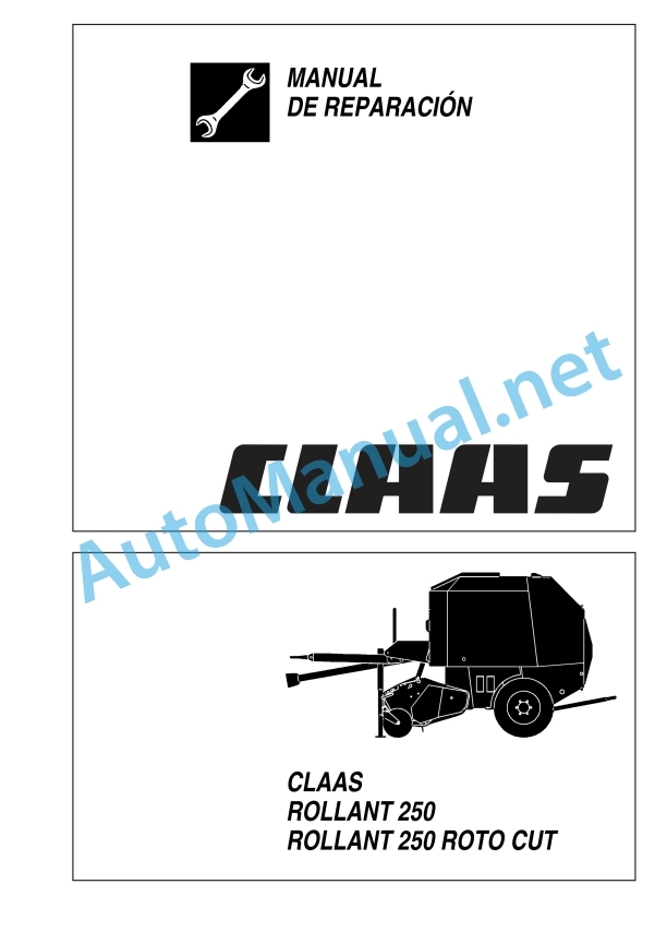
Claas Rollant 250 Rc (725) Baler Repair Manual ES
$300.00
- Model: Rollant 250 Rc (725) Baler
- Type Of Manual: Repair Manual
- Language: ES
- Format: PDF(s)
- Size: 58.7 MB
File List:
00 0298 444 0.pdf
00 0298 444 0.pdf:
General indications
General indications
Introduction
Introduction to the CLAAS repair manual
Explanation of symbols
Security measures
Important note
Warning and danger signs
Proper machine application
General prescriptions for safety and accident prevention
Move away from the machine
Maintenance
Fundamental rule
General repair instructions
Cause of the fault
Replacement parts
Tension of steel roller chains
Tapered ring joints
Mounting:
Disassembly:
Self-locking screws
Liquid screw insurance
Correct mounting of bearings with retaining ring
Correct assembly of bearings with tensioner sleeve
Squeeze in:
Threaded joints with adjusting ring in hydraulic pipes
Pre-assembly:
Final assembly:
Repeat montage:
Union with non-airtight adjusting ring:
Threaded joints with progressive ring in hydraulic pipes
Pre-assembly:
Final assembly:
Non-hermetic profile ring connection:
Threaded joints with sealing cone in hydraulic pipes
Mounting:
Welding work
The repair will be carried out quickly and correctly if the following is observed:
Tightening torques
Hydraulic unions
Technical data
Lubrication table
cardan shaft
Disassemble the cardan half shaft (tractor side)
Assemble the cardan half shaft (x0011_side_of_x0011_tractor)
Disassemble the cardan shaft (machine side)
Assemble the cardan half shaft (machine side)
Disassemble the clutch cam switch
Assemble the clutch cam switch
Bevel gear, gear train
Remove the bevel gear
Disassemble the bevel gear
Bevel gear (540/min.) disassembled:
Assemble the bevel gear
Assemble the bevel gear
Drive diagram
Drives on the left
Drives on the right
Left drive chains
Remove the roller drive (top)
Assemble and tension the roller drive (above)
Remove the roller drive (front)
Install the roller drive (front)
Dismantling the drive for the cutting rotor / feed rotor
Assembling and adjusting the drive for the cutting rotor/feed rotor
Dismantle the drive for rollers_x0011_1, 2 and 16
Assemble and adjust the drive for rollers 1, 2 and 16
Remove the drive for the collector (left)
Install the drive for the collector (left)
Dismantle the gear train to drive the collector on the rotor
Assemble the gear train to drive the pickup on the rotor
Drive chains / drive belts on the right
Dismantle the _x0004_feed auger drive (right)
Assemble the _x0004_feed auger drive (right)
Remove the roller drive for the tailgate
Assembling the roller drive for the tailgate
Remove the drive for the tying system and dismantle it
Assemble the drive for the tying system and mount it
Disassembling and installing the drives for mesh tying / twine tying
Pickup/rollers
Picker – elevator
Dismantle the hydraulic lifting of the Pickup
Assemble the hydraulic lifting of the Pickup
Remove the support wheel
Disassemble the support wheel
Disassembled support wheel
Assemble the support wheel
Remove the diverter plate
Install the diverter plate
Replacing the elastic tines
Pickup, remove the auger
Pickup, auger disassembled
Pickup, mount the auger
Replace the tension ring bearing (left) for the drive shaft
Replace the tension ring bearing (right) for the drive shaft
Disassemble the collector
Assemble the collector
Remove the eccentric disc
Remove the rollers
Remove the tine holders
Remove the drive shaft
Disassembled picker
Assemble the pick holders
Install the eccentric disc
Cutting/feeding system
Remove cutting rotor / feed rotor
Disassemble the cutting rotor/feed rotor
Cutting rotor / feed rotor disassembled
Assemble cutting rotor/feed rotor
Install the cutting rotor / _x0004_feed rotor
Remove the cutting rotor/feed rotor drainer
Install the cutting rotor/feed rotor drainer
Remove the blade shaft
Disassembled blade shaft
Assemble the blade shaft
Remove roller 3
Roller 3 disassembled
Install roller 3
Remove roller 11
Remove the tailgate
Roller 3 disassembled
Install the roller 11
Tilting segment
Remove the swing segment
Disassemble the swing segment
Assemble the tilt segment
Install the tilting segment
Disassemble the reverse rotation hydraulic system
Reverse rotation hydraulic system disassembled
Assemble the reverse rotation hydraulic system
Replace the reverse rotation mechanical system
Bound by thread and bound by mesh
tied by thread
Dismantle the thread binding
Disassemble the cutting system
Remove the separator
Dismantle the thread binding
Disassemble the cutting system
Disassembled thread bound (construction and control):
Disassembled thread tying (thread brake):
Disassembled thread tying (thread guide):
Tied by disassembled thread (separator):
Assemble the cutting system
Assemble the twine tying
Assemble the separator
Assemble the cutting system
Assemble the thread tying
tied by mesh
Dismantle the mesh tying
Dismantle mesh bundling
Disassembled mesh tying (brake for mesh coil):
Disassembled mesh tying (construction and pressure roller):
Disassembled mesh brake (roller and blade):
Disassembled twine tying (blade pretensioning – standard equipment):
Assemble mesh tying
Assemble the mesh tying
machine body
Back door
Remove the tailgate
Install the tailgate
Hydraulic installation – electrical installation
Valve combination
Check the tightness of the valve combination and the hydraulic cylinder for the gate.
Disassemble the valve combination
Disassemble the valve combination
Disassembled valve combination
Assemble the valve combination
Dismantle the 4/3-way directional control valve with circulation blocking valve
Dismantle the 4/3-way distributor valve with circulation blocking valve
Assemble the 4/3-way distributor valve with circulation blocking valve
Install the 4/3-way distributor valve with circulation blocking valve
Dismantle the NG2 solenoid valve
Disassemble the NG2 solenoid valve
Disassembled NG2 solenoid valve
Assemble the NG2 solenoid valve
Assemble the NG2 solenoid valve
Hydraulic cylinder
Disassemble and install the hydraulic cylinder
Disassemble the hydraulic cylinder
Disassembled hydraulic cylinder:
Assemble the hydraulic cylinder
Disassemble the hydraulic cylinder (blade lifting)
Disassembled hydraulic cylinder:
Assemble the hydraulic cylinder (blade lifting)
Alphabetical index
Alphabetical index
John Deere Repair Technical Manual PDF
John Deere Repair Technical Manual PDF
John Deere Parts Catalog PDF
John Deere Harvesters 8500 and 8700 Parts Catalog CPCQ24910 Spanish
John Deere Repair Technical Manual PDF
John Deere Repair Technical Manual PDF
John Deere PowerTech M 10.5 L and 12.5 L Diesel Engines COMPONENT TECHNICAL MANUAL CTM100 10MAY11
John Deere Repair Technical Manual PDF
John Deere 18-Speed PST Repair Manual Component Technical Manual CTM168 10DEC07
John Deere Repair Technical Manual PDF
John Deere 16, 18, 20 and 24HP Onan Engines Component Technical Manual CTM2 (19APR90)
John Deere Repair Technical Manual PDF
John Deere Repair Technical Manual PDF
John Deere POWERTECH E 4.5 and 6.8 L Diesel Engines TECHNICAL MANUAL 25JAN08


