Claas Trion 660-640 (L54) Combines Repair Manual ES
$300.00
- Model: Trion 660-640 (L54) Combines
- Type Of Manual: Repair Manual
- Language: ES
- Format: PDF(s)
- Size: 137 MB
File List:
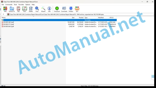
00 0305 246 3.pdf
00 0305 371 0.pdf
00 0305 843 0.pdf
00 0305 371 0.pdf:
Cummins L9 CM2350 L133CCummins QSL9 CM2350 L120C
Introduction
Information regarding the instruction manual
Manual validity
Copyright notice
Information regarding this repair manual
Using the manual
Structuring with construction group structure
Search and find
Direction signs
General repair instructions
Technical instructions
Indications for correct repair
Self-locking screws
Liquid screw insurance
Steel roller chains
connecting link
Type E connecting link with spring
Type G connecting link with wire
S type connecting link with pins
Tapered ring joints
Disassembly
Mounting
Head key joints
Disassembly
Mounting
Bearings with tension ring
Disassembly
Mounting
Bearing with tensioner sleeve
Disassembly
Mounting
Tension bushing
Disassemble
Disassembly version A
Disassembly version B
Tension bushing version A
Tension bushing version B
Safety rings
Radial shaft seal rings
Hose clamps
Tightening torques
Hose orientation
Auxiliary assembly material
Assembly tools
Screw connections with adjustment ring
Screw connections with non-sealed adjusting ring
Screw connections with sealing cone
Hydraulic hoses
Laying of hoses
Diaphragm accumulator (pressure accumulator) based on factory regulations CLAAS CN 24 0403
Signaling
Operational means
Service and assembly
Changing the gas filling
special tool
Joint surface work
Replacement parts
Consumables
Welding work
ESD protection measures
special tool
ESD protection measures
Instructions for testing and repair
Tightening torques
Types of screw connections according to CLAAS CN 02 5000 factory regulations
Screwdriving case description
Tolerance class
Tightening prescription
Tightening torques for ISO metric threads
Tightening torques for metric fine thread
Tightening torques for hydraulic bolted connections with cutting ring
Tightening torques for fittings with tapered seal connection and hydraulic connections with soft seal ring
Tightening torques for bulkhead fitting nuts, straight and angled
Tightening torques for SDS form B and E hydraulic threaded fittings
Tightening torques for threaded fittings of the SDS hydraulic system form F and sealing screw
Tightening torques for threaded fittings of the SDS hydraulic installation form H
Tightening torques for form E plug screws
Tightening torques for threaded fittings of the hydraulic installation form C, conical thread
Tightening torques for threaded fittings of the SDE hydraulic installation form F, adjustable direction
Tightening torques for SDE form H hydraulic threaded fittings, adjustable
Tightening torques for oscillating hydraulic threadings
Tightening torques for hollow screws (with copper gasket)
Tightening torques for brake pipe threading
Tightening torques for pipe supports with O-ring and union nuts
Tightening torques for threaded grub screws / diaphragms
Tightening torques for grub screws and special screws
Tightening torques for hydraulic parts
Tightening torques for hexagonal sealing nuts
Tightening torques for hose clamps
Assembly instructions
Helical thread tightening clamps
Hose clamps with round bolt
Security
Recognize warning signs
Danger symbols
Safety instructions
Graphic danger symbols and warning indications
Requirements for technical personnel
Children in danger
Machine danger zones
Accompanying instructor during work
Risk of injury due to rotating shafts
Construction modifications to the machine
Optional equipment and spare parts
Control of the machine running
Technical status
Comply with technical limit values
Danger from machine parts during coasting
Keep protective devices operational
Personal protective equipment
Wear appropriate clothing
Remove dirt and loose objects
Park the machine safely
Unsuitable consumables
Safe handling of consumables and auxiliary materials
Environmental protection and waste disposal
Keep the cabin free of chemicals
Fire prevention
Lethal electrical shock due to overhead power lines and lightning strikes
Current discharge through the electrical installation
Noise can cause health damage
Prestressed machine parts
Liquids under pressure
Air under presure
Toxic exhaust gases
Hot surfaces
Safe ascent and descent
Only work on the stopped machine
Dangers in repair work
Machine parts and lifted loads
Danger from welding work
Check and charge the battery
Emergency Preparations
CCN Explanation
CCN (CLAAS Component Number)
General indications
Electrical regulations
Hydraulic regulations
CCN (CLAAS Component Number)
01 Engine
0102 Complete component
Technical data
Technical data
Diesel engine summary
Summary exhaust gas aftertreatment
Diesel engine summary
Disassemble the engine
Summary (304-999)
Disarm (304-001)
Assemble the engine
Summary (305-999)
Arm (305-001)
Turn engine (000-017)
special tool
Hemispherical plug (017-002)
Disassemble
Clean and check
Blanking screw (017-007)
Disassemble
Clean and check
Blanking screw (017-007)
Disassemble
Clean and check
Crankcase, center
Blanking screw with cylindrical thread (017-011)
Disassemble
Clean and check
Blanking screw with cylindrical thread (017-011)
General information
Disassemble
Clean and check
Expansion screw (017-015)
Disassemble
Clean and check
0110 Engine casing
Crankshaft gasket, front (001-023)
special tool
Disassemble
Clean and check
Crankshaft gasket, front (001-023)
special tool
Disassemble
Clean and check
Crankshaft gasket, rear (001-024)
special tool
General information
lip seal
Multi-piece joint
Disassemble
lip seal
Multi-piece joint
Clean and check
Sprocket Cover, Front (001-031)
Disassemble
Clean and check
Gearbox, front (001-033)
Disassemble
Clean and check
Crankcase gasket – repair
Bleeding crankcase (external) (003-001)
Disassemble
Clean and check
Crankcase Bleeder (Internal) (003-002)
General information
Disassemble
Crankcase Bleeder (Internal) (003-002)
Disassemble
Clean and check
Crankcase purge line (003-018)
Disassemble
Clean and check
Crankcase purge line (003-018)
Disassemble
Block-mounted crankcase bleeder
Valve Cover Mounted Crankcase Bleed
Clean and check
Block-mounted crankcase bleeder
Valve cover mounted crankcase bleeder
Crankcase (007-025)
Preparation for work
Disassemble
Clean and check
Composite oil pan only
Flywheel housing (016-006)
special tool
Disassemble
Clean and check
Orientation of the front surfaces
Drill orientation
Wet flywheel applications
Flywheel housing (016-006)
special tool
Disassemble
Clean and check
Orientation of the front surfaces
Drill orientation
Wet flywheel applications
Wet flywheel applications
Crankcase pressure sensor (019-445)
General information
Disassemble
Clean and check
0115 Engine propulsion
Connecting rod bearing (001-005)
Disassemble
Clean and check
Main bearing (001-006)
special tool
Disassemble
Clean and check
Upper main bearings
Lower main bearings
Main bearing (001-006)
special tool
Disassemble
Clean and check
Upper main bearings
Lower main bearings
Connecting Rod (001-014)
Disassemble
Clean and check
Checking bending and twisting
Calibration process
Connecting Rod (001-014)
General information
Disassemble
Clean and check
Checking bending and twisting
Calibration process
Crankshaft (001-016)
special tool
Disassemble
Clean and check
Rotation Check
Crankshaft (001-016)
special tool
General information
Disassemble
Clean and check
Rotation Check
Crankshaft sprocket, front (crankshaft removed) (001-019)
Disassemble
Clean and check
Crankshaft pulley (001-022)
Disassemble
Find out
Crankshaft wear bushing, front (001-025)
special tool
Disassemble
Clean and check
Piston (001-043)
Preparation for work
General information
Disassemble
Clean and check
Failure analysis/inspection
Piston cooling nozzle (001-046)
Disassemble
Clean and check
Piston cooling nozzle (001-046)
Disassemble
Clean and check
Piston rings (001-047)
Preparation for work
Failure analysis/inspection
Rubber vibration damper (001-051)
Disassemble
Viscose Vibration Dampener (001-052)
Disassemble
Find out
Piston-connecting rod construction group (001-054)
special tool
Disassemble
Engines with horizontally divided connecting rods
Clean and check
One-piece piston
Multi-piece piston
Engines with pins and nuts on the connecting rods
Engines with connecting rod cap screws
Piston-connecting rod construction group (001-054)
special tool
Disassemble
Engines with horizontally divided connecting rods
Engines with obliquely divided connecting rods
Clean and check
One-piece piston
Multi-piece piston
Engines with pins and nuts on the connecting rods
Engines with connecting rod cap screws
Crankshaft wear bushing, rear (001-067)
special tool
Initial check
Disassemble
Clean and check
Crankshaft speed ring (001-071)
Disassemble
Clean and check
Crankshaft gasket bracket, rear (001-104)
special tool
Disassemble
Clean and check
Maintenance advice
Ring gear disc (016-004)
Initial check
Mechanics
Electrical installation
Disassemble
Check the feasibility of reuse
Flywheel (016-005)
special tool
Initial check
Mechanics
Electrical installation
Disassemble
Clean and check
Non-round drill
Side blow
Flywheel Sprocket (016-008)
General information
Initial check
Disassemble
Crankshaft position sensor (019-365)
General information
Disassemble
Clean and check
0120 Cylinder head / valves / distributor wheel
Camshaft (001-008)
Disassemble
Clean and check
Camshaft (001-008)
Disassemble
Clean and check
Camshaft bushings (001-010)
General information
Disassemble
Clean and check
Camshaft Sprocket (Mounted Camshaft) (001-012)
special tool
Disassemble
Clean and check
Camshaft sprocket (camshaft removed) (001-013)
Disassemble
Clean and check
Cylinder block (001-026)
Preparation for work
Disassemble
Initial check
Clean and check
Cylinder bushing (001-028)
special tool
General information
Initial check
Disassemble
Clean and check
Mounting
Cylinder block bushing seat (001-058)
Initial check
Prosecution
Cylinder block reinforcement plate (001-089)
General information
Disassemble
Clean and check
Valve bridge (002-001)
Disassemble
Clean and check
Valve bridge (002-001)
Disassemble
Clean and check
Cylinder head (002-004)
special tool
Disassemble
Clean and check
Cylinder head (002-004)
special tool
Disassemble
Clean and check
Cylinder head valve guide gasket (002-016)
Preparation for work
special tool
General information
Disassemble
Clean and check
Cylinder head valve guide gasket (002-016)
Preparation for work
special tool
General information
Disassemble
Clean and check
Head gasket (002-021)
Disassemble
Cylinder head group (003-004)
Technical instructions
special tool
Preparatory work
Final jobs
Tilt lever (003-008)
Technical instructions
Disassemble
Clean and check
Tilt lever cover (003-011)
Disassemble
Clean and check
Tilt lever cover (003-011)
Disassemble
Clean and check
Valve cover with screw connection on the outer edge
Valve cover with medium screw connection
Valve cover with screw connection on the outer edge
Tilt lever housing (003-013)
Preparation for work
Disassemble
Clean and check
Pusher tubes and rods (004-014)
Disassemble
Clean and check
Pusher (004-015)
Preparation for work
special tool
Disassemble
Clean and check
Pusher (004-015)
Preparation for work
special tool
Disassemble
Sliding pushers
roller pusher
Clean and check
Sliding pushers
roller pusher
Sliding pushers
roller pusher
Camshaft sensor (019-363)
General information
Disassemble
Clean and check
0125 Fuel/injection system
Fuel pump (005-016)
Technical instructions
special tool
Preparatory measures
Disassemble
Find out
Fuel pump (005-016)
Technical instructions
special tool
Preparatory measures
Disassemble
Find out
Fuel pump (005-025)
Preparatory measures
Disassemble
Clean and check
Fuel Pump Adjustment (005-037)
Disassemble
Clean and check
Fuel conveyor pump (005-045)
General information
Preparatory measures
Disassemble
Outlet fitting on fuel pump head (005-226)
Preparatory measures
Disassemble
Disassembly of a flat sealing disc
Clean and check
Fuel Pump Heads (005-227)
special tool
Preparatory measures
Disassemble
Clean and check
Fuel Pump Heads (005-227)
special tool
Preparatory measures
Disassemble
Clean and check
steel piston
Ceramic piston
Fine tunning
Fuel pump actuator housing (005-228)
Preparatory measures
Disassemble
Clean and check
Engine Control Module (ECM) Coolant Plate, Fuel Cooled (006-006)
Preparatory measures
Initial check
Disassemble
Find out
Fuel outlet ducts (006-013)
Preparatory measures
Initial check
Disassemble
Find out
Fuel distributor (006-019)
Preparatory measures
Disassemble
Find out
Fuel distributor with screw fittings
Fuel distributor with screw fittings
Fuel inlet ducts (006-024)
Preparatory measures
Initial check
Disassemble
Find out
Injection nozzle (006-026)
special tool
Preparatory measures
Disassemble
Clean and check
High pressure inlet ducts to injection nozzles (006-051)
Preparatory measures
Initial check
Disassemble
Clean and check
High pressure inlet ducts to injection nozzles (006-051)
Preparatory measures
Initial check
Disassemble
Find out
Fuel Line Connection (Cylinder Head Mounted) (006-052)
special tool
Preparatory measures
Disassemble
Clean and check
High pressure accumulator (rail) (006-060)
Technical instructions
Preparatory measures
Initial check
Disassemble
Clean and check
Pressure limiting valve (006-061)
Technical instructions
Preparatory measures
Disassemble
Find out
Pressure limiting valve (006-061)
Technical instructions
Preparatory measures
Disassemble
Find out
Fuel distributor high pressure fitting (006-067)
Technical instructions
Preparatory measures
Initial check
Disassemble
Pressure relief in high pressure fuel system (006-081)
Preparatory measures
Release pressure
Rail pressure sensor (019-115)
Technical instructions
Preparatory measures
Disassemble
Clean and check
Fuel Pump Actuator (019-117)
Technical instructions
Preparatory measures
Initial check
Disassemble
0130 Lubricating oil system
Engine oil preheater (007-001)
Disassemble
Clean and check
Lubricating oil radiator (007-003)
Disassemble
Clean and check
Checking the tightness
Oil cooler without slit
Oil cooler with slit
Lubricating oil radiator (007-003)
Disassemble
Clean and check
Checking the tightness
Oil level check dipstick (007-009)
Calibrate
Oil level dipstick tube (007-011)
Disassemble
Oil level dipstick tube (007-011)
Disassemble
Lubricating oil filter (007-013)
Lube Oil Filter Bypass Valve (007-014)
Disassemble
Clean and check
Lube Oil Filter Head (007-015)
Disassemble
Clean and check
Lube oil filter head (separately mounted) (007-017)
Disassemble
Clean and check
Lube Oil Filter Head Adapter (007-018)
Disassemble
Clean and check
Lube Oil High Pressure Outlet Valve (007-021)
Disassemble
Find out
Lube Oil Pressure Regulator (Main Channel) (007-029)
Disassemble
Clean and check
Oil pump (007-031)
Disassemble
Clean and check
Oil absorption tube (mounted on cylinder block) (007-035)
Disassemble
Clean and check
Oil thermostat (007-039)
Disassemble
Clean and check
Lubricating oil passages (007-092)
Disassemble
Find out
Turbocharger oil outlet pipe (010-045)
Disassemble
Clean and check
Turbocharger oil outlet pipe (010-045)
Disassemble
Clean and check
Turbocharger oil inlet passage (010-046)
Disassemble
Clean and check
Turbocharger oil inlet passage (010-046)
Disassemble
Find out
Engine Oil Pressure Switch and Sensor (019-066)
Disassemble
Clean and check
0135 Cooling system
Coolant thermostat (008-013)
Disassemble
Clean and check
Coolant purge lines (008-017)
General information
Disassemble
Clean and check
Water pump (008-062)
Disassemble
Clean and check
Water inlet connection (008-082)
Preparation for work
Disassemble
Clean and check
Coolant lines (008-124)
Preparation for work
Disassemble
Clean and check
Turbocharger Coolant Hoses (010-041)
Preparation for work
Disassemble
Clean and check
Turbocharger Coolant Hoses (010-041)
Preparation for work
Disassemble
Clean and check
Coolant temperature sensor (019-019)
General information
Disassemble
Clean and check
0140 Exhaust gas system
Turbocharger (010-033)
Preparation for work
special tool
Check that it is the correct part
Disassemble
Clean and check
Turbocharger (010-033)
Preparation for work
Disassemble
Clean and check
Check axial play
Check radial clearance
Intake pressure regulating valve (010-050)
Initial check
Disassemble
Clean and check
Turbocharger compressor outlet connection (010-132)
special tool
Disassemble
Clean and check
VTG Turbocharger Actuator, Electric (010-134)
Disassemble
Clean and check
Calibrate
Calibration orders
Turbocharger Exhaust Gas Connection Adapter (010-141)
Disassemble
Clean and check
Exhaust elbow, dry (011-007)
General information
Disassemble
Clean and check
Exhaust elbow, dry (011-007)
Disassemble
Clean and check
Only with several pieces:
Exhaust gas pressure sensor duct (011-027)
Initial check
Disassemble
Clean and check
Exhaust gas pressure sensor (019-376)
Disassemble
0145 Air suction
Air suction elbow (010-023)
Disassemble
Clean and check
Cold start aid (010-029)
General information
Cold start aid (010-029)
Disassemble
Clean and check
Air suction connection (010-080)
special tool
General information
Disassemble
Clean and check
Air suction connection (010-080)
Disassemble
Clean and check
Cover, air intake elbow (010-108)
Disassemble
Clean and check
FIPG gasket at the junction of the intake elbow cover and the cylinder head
Standard gasket at the junction of the suction elbow cover and the cylinder head
Air suction connection adapter (010-131)
General information
Disassemble
Clean and check
Air suction connection adapter (010-131)
Disassemble
Clean and check
Suction elbow pressure/temperature sensor (019-159)
Disassemble
Clean and check
0150 Engine coupled parts
Refrigerant lines, air compressor (012-004)
Disassemble
Find out
Air Compressor Cylinder Head, Single Cylinder (012-007)
Initial check
Disassemble
Clean and check
Air Compressor Cylinder Head, Single Cylinder (012-007)
Initial check
Disassemble
Clean and check
Air Compressor (012-014)
special tool
Disassemble
Clean and check
Air Compressor (012-014)
Preparation for work
special tool
Disassemble
Clean and check
Wabco™ Air Compressor
Knorr™ Brake – Air Compressor
Air Compressor Inlet Duct (012-109)
General information
Disassemble
Clean and check
Oil inlet passage, air compressor (012-110)
Disassemble
Clean and check
Dynamo (Generator) (013-001)
Initial check
Disassemble
Charging system – dynamo support (013-003)
Disassemble
Starter motor (013-020)
Preparation for work
special tool
Rotation Check
Disassemble
Clean and check
Cummins brand starter motor:
Non-Cummins brand starter motor:
0155 Engine adjustment
Engine control module (019-031)
Disassemble
Engine Wiring Harness (019-043)
General information
assemble
Find out
Wiring harness, internal actuator (019-063)
Disassemble
Find out
Delphi 96 Way Plug-in Connector for Engine Control Module (019-505)
special tool
General information
Disassemble
Replace the pin
Disassembly of the terminals
Place the terminal
0165 Exhaust gas aftertreatment
SCR Catalyst (011-036)
General information
Disassemble
Clean and check
Diesel particulate filter (011-041)
General information
Disassemble
Clean and check
Diesel Particulate Filter Differential Pressure Sensor Ducts (011-047)
General information
Disassemble
Clean and check
Diesel oxidation catalyst (011-049)
General information
Disassemble
Clean and check
In Side-in configurations
In End-in configurations
Exhaust Gas Aftertreatment System (011-050)
General information
Disassemble
Exhaust Gas Aftertreatment System Decomposition Pipe (011-062)
General information
Initial check
Disassemble
Clean and check
Diesel particulate filter sensor assembly bracket (011-141)
General information
Disassemble
Clean and check
Decomposition tube sensor assembly bracket (011-142)
General information
Disassemble
Clean and check
Diesel Particulate Filter Differential Pressure Sensor (019-443)
General information
Disassemble
Clean and check
Exhaust gas aftertreatment system exhaust gas temperature sensor (019-449)
General information
Initial check
Disassemble
Find out
NOx sensor at the outlet of the exhaust aftertreatment system (019-451)
General information
Disassemble
Clean and check
NOx sensor at the inlet of the exhaust aftertreatment system (019-463)
General information
Disassemble
Clean and check
00 0305 843 0.pdf:
LEXION 8900-5300TRION 750-520
00 2998 428 0
Validity
Safety instructions
Supply set
Repair kit supply set 00 2998 428 0
Work preparation
Preparation of work, repair kit 00 2998 428 0
Mounting
Replace shaft and bearing
John Deere Repair Technical Manual PDF
New Holland Service Manual PDF
John Deere Repair Technical Manual PDF
John Deere Repair Technical Manual PDF
John Deere Transmission Control Unit Component Technical Manual CTM157 15JUL05
John Deere Repair Technical Manual PDF
John Deere Parts Catalog PDF
John Deere Tractors 7500 Parts Catalog CPCQ26568 30 Jan 02 Portuguese
John Deere Repair Technical Manual PDF
John Deere Repair Technical Manual PDF
John Deere POWERTECH E 4.5 and 6.8 L Diesel Engines TECHNICAL MANUAL 25JAN08
John Deere Repair Technical Manual PDF
John Deere Repair Technical Manual PDF


