Claas Jaguar 900-830 (492) Forage Harvesters Operator Manual ES
$50.00
- Model: Jaguar 900-830 (492) Forage Harvesters
- Type Of Manual: Operator Manual
- Language: ES
- Format: PDF(s)
- Size: 75.8 MB
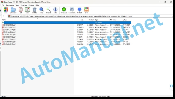
File List:
00 0292 502 0.pdf
00 0293 926 0.pdf
00 0294 371 4.pdf
00 0294 628 4.pdf
00 0295 292 0.pdf
00 0295 510 2.pdf
00 0295 778 1.pdf
00 0298 869 2.pdf
00 2308 681 3.pdf
00 0292 502 0.pdf:
Introduction
Information on the instruction manual
Manual validity
Maintenance
Turn off the machine and secure it
Turn off the machine and secure it
Eliminate a fault in the flow
Eliminate flow failure
00 0294 371 4.pdf:
JAGUAR 900 – 830
Regarding this instruction manual
General data
Manual validity
Management of CIS
General data
Functions and indications
Before first start-up
Driver’s cabin/platform
Overview – Status indicators A (up to machine number…)
Overview – Screen area B (up to machine number…)
Overview – status displays A (from machine number…)
Overview – Screen area B (from machine number…)
Overview – key area C
Call functions/operation data
Modify values
Indicate and set the time
Indicate the total sum of work hours (CIS with on-board reporter)
Enter / reset the daily sum of working hours (CIS with on-board reporter)
Indicate operating hours
Indicate/reset daily area (CIS with on-board informant)
Indicate surface performance (CIS with on-board reporter)
Indicate the total area (CIS with on-board indicator)
Upcoming maintenance interval / indicate elapsed time (CIS with on-board indicator)
Confirm the maintenance carried out (CIS with on-board reporter)
Set pulses/100 m
Set pulses/100 m per calibration run.
Set pulses/100 m by direct entry
Adjust the unit
Memorize the working position (CIS with on-board information)
Adjust working width (CIS with on-board indicator)
Adjusting the front implement partition (CIS with on-board information)
Adjust partial width of front implement (CIS with on-board indicator)
Learning the gear lever
Adjust driving strategy
Power set
Check the pressure of the lifting hydraulic cylinder during the support pressure regulation
Control current head height / cutting height preselection
Program the Contour end stops
Check the potentiometer for the head height
Adjust the potentiometer for the head height
Feeding run stops
Learn Autopilot
Attached parts, machine housing
Adjust the dosage of silage additives (from the machine number…)
Indicate engine load
Indicate the engine revolutions
Program the working revolution regime
Fuel consumption indicator (additional equipment)
Automatic sharpening and bedknife system
Define the number of sharpening cycles
Sharpening reminder function
Set the time interval until the next sharpening
Check the time until the next sharpening
Connect the automatic sharpening system
Control the automatic sharpening system
Reset total sharpening cycles
Adjust bedknife distance
Connect the automatic bedknife system
Monitor the automatic bedknife system
Set the residual state of the blades to their base value
Adjust the base position of the bedknife
Check the sensors of the automatic sharpening system and the bedknife
Corn Cracker
Show distance between corn-cracker rollers (optional equipment)
Program the distance between the corn-cracker rollers (optional equipment)
Grain tank unloading
Learn Discharge Elbow End Stops
Incident and solution
CIS alarm types
CIS fault code table
00 0294 628 4.pdf:
1. Introduction
1.1 General instructions
1.1.1 Using the instructions
1.1.2 Validity of instructions
2 Security measures
2.1 Observe
2.1.1 Especially important
2.1.2 Warning and danger signs
3 Supply set
3.1 Quantimeter with COMMUNICATOR
3.1.1 Retrofit kit 000 140 982 1 / 009 100 870 4
4 Assembly
4.1 Set up COMMUNICATOR performance measurement
4.1.1 Transform the central electrical system
4.1.2 Install the cable set
4.1.3 Installing the COMMUNICATOR control element
4.1.4 Disassemble the power supply casing
4.1.5 Mount the angle sensor
4.1.6 Assemble the power housing
4.1.7 Connect the angle sensor
4.1.8 Prepare and perform a functional test
5 Before first start-up
5.1 General instructions
5.1.1 Checklist for first start-up
6 Operation CLAAS COMMUNICATOR
6.1 General instructions
6.1.1 CLAAS COMMUNICATOR
6.2 Control element and display
6.2.1 Control element
6.2.2 Chopper menu with progress screen
6.2.3 Chopper menu with work screen
6.3 Menu structure
6.3.1 Select menu
6.3.2 Chopper menu summary
6.3.3 Advance screen menu / work screen
6.3.4 Orders menu
6.3.5 Counterbalanced menu
6.3.6 Calibration menu
6.3.7 Counter menu
6.3.8 Service menu summary
6.4 Calibration
6.4.1 Determine the calibration measurement and adjust it
6.4.2 Adjust the reaction threshold
6.4.3 Zero crack learning
Alphabetical index
00 0295 292 0.pdf:
1. Introduction
1.1 General instructions
1.1.1 Using the instructions
1.1.2 Validity of instructions
2 Security measures
2.1 Observe
2.1.1 Especially important
2.1.2 Warning and danger signs
3 Supply set
3.1 Quantimeter with CLAAS CEBIS MOBILE
3.1.1 Retrofit kit 009 101 592 7 / 009 101 592 8
4 Assembly
4.1 Set up the CLAAS CEBIS MOBILE performance measurement
4.1.1 Transform the central electrical system
4.1.2 Install the cable set
4.1.3 Installing the CEBIS MOBILE control element
4.1.4 Disassemble the power supply casing
4.1.5 Mount the angle sensor
4.1.6 Assemble the power housing
4.1.7 Connect the angle sensor
4.2 Assemble yield mapping (supplementary equipment) CEBIS MOBILE
4.2.1 Mount the GPS antenna (supplementary equipment)
5 Before first start-up
5.1 General instructions
5.1.1 Checklist for first start-up
6 Before each start-up
6.1 CLAAS CEBIS MOBILE
6.1.1 Insert the chip card
7 Operation CLAAS CEBIS MOBILE
7.1 General instructions
7.1.1 CLAAS CEBIS MOBILE
7.2 Control element and display
7.2.1 Control element
7.2.2 Chopper menu with progress screen
7.2.3 Chopper menu with work screen
7.2.4 Orders menu
7.3 Menu structure
7.3.1 Select menu
7.3.2 Chopper menu summary
7.3.3 Menu progress screen / work screen
7.3.4 Counterbalanced menu
7.3.5 Calibration menu
7.3.6 Counter menu
7.3.7 Order menu summary
7.3.8 Orders menu
7.3.9 GPS Menu
7.3.10 Settings menu
7.4 Calibration
7.4.1 Determine the calibration measurement and adjust it
7.4.2 Adjust the reaction threshold
7.4.3 Zero crack learning
Alphabetical index
00 0295 510 2.pdf:
JAGUAR 900 – 830
1. Introduction
1.1 General data
1.1.1 Use of the manual
1.1.2 Validity of the manual
1.1.3 Technical data
1.1.4 Road traffic
1.1.5 Note regarding electronic engine management
1.1.6 Information regarding the metal detector
1.1.7 Information regarding the stone detector
1.2 Identification plates and identification numbers
1.2.1 Spare parts and technical queries
1.2.2 Machine identification plate
1.2.3 Chopping unit identification plate
1.2.4 Mercedes-Benz OM 502 LA engine identification plate
1.2.5 Mercedes-Benz OM 457 LA and OM 460 LA engine identification plate
1.2.6 Drive shaft identification plate
1.2.7 Hitch mouth identification plate (additional equipment)
1.3 Attached parts, machine housing
1.3.1 Access to the workplace and maintenance stations
2 Security
2.1 General data
2.1.2 To take special account
2.1.3 Proper machine application
2.1.4 Intended knowing misuse
2.1.5 Prescriptions for safety and accident prevention
2.1.6 Safety rules and accident prevention rules Mincers
2.1.7 Before commissioning
2.1.8 Additional weights
2.1.9 Load and tie down the machine
2.1.10 Carry additional passengers
2.1.11 General driving
2.1.12 Forage chopper driving
2.1.13 Driving on slopes
2.1.14 Getting off the machine
2.1.15 Headers and trailers
2.1.16 Mincer chopper device
2.1.17 Air conditioning installation
2.1.18 Adjustment and maintenance work
2.1.19 Pressure accumulator
2.1.20 Antifreeze
2.1.21 First aid measures
2.1.22 Decommissioning and waste disposal
2.1.23 Startup mirror – right side of the machine
2.1.24 Shims
2.1.25 Fire extinguisher
2.1.26 Battery separator switch
2.1.27 Risk of accident due to hydraulic fluid
2.2 Safety instructions
2.2.2 Signage of warning and danger indications
2.3 Graphic danger symbols
2.3.1 General information on warning signs
2.3.2 Placement of graphic danger symbols
3 Technical data
3.1 JAGUAR 900 / 890 Speedstar
3.1.1 General instructions
3.1.2 Measurements
3.1.3 Weights
3.1.4 Electrical installation
3.1.5 Driver’s cabin/platform
3.1.6 Power
3.1.7 Undercarriage
3.1.8 Chassis tire air pressure
3.1.9 Engine
3.1.10 Chop
3.1.11 Eject
3.1.12 Central lubrication system
3.2 JAGUAR 870 / 850 / 830 Speedstar
3.2.1 General instructions
3.2.2 Measurements
3.2.3 Weights
3.2.4 Electrical installation
3.2.5 Driver’s cabin/platform
3.2.6 Power
3.2.7 Undercarriage
3.2.8 Chassis tire air pressure
3.2.9 Engine
3.2.10 Chop
3.2.11 Eject
3.2.12 Central lubrication system
3.3 JAGUAR 900 / 890 Profistar
3.3.1 General instructions
3.3.2 Measurements
3.3.3 Weights
3.3.4 Electrical installation
3.3.5 Driver’s cabin/platform
3.3.6 Power
3.3.7 Undercarriage
3.3.8 Chassis tire air pressure
3.3.9 Engine
3.3.10 Chop
3.3.11 Eject
3.3.12 Central lubrication system
3.4 JAGUAR 870 / 850 / 830 Profistar
3.4.1 General instructions
3.4.2 Measurements
3.4.3 Weights
3.4.4 Electrical installation
3.4.5 Driver’s cabin/platform
3.4.6 Power
3.4.7 Undercarriage
3.4.8 Chassis tire air pressure
3.4.9 Engine
3.4.10 Chop
3.4.11 Eject
3.4.12 Central lubrication system
4 Before start-up
4.1 Before commissioning
4.1.1 Checklist for first start-up
4.2 Cabin
4.2.1 Cabin with automatic air conditioning
4.2.2 Automatic air conditioning system
4.2.3 Install the fan/air conditioning fuse
4.2.4 Connect the air conditioning automation
4.2.5 Adjust the cabin temperature
4.2.6 Manually adjust the speed of the vaporizer-fan
4.2.7 Switching on ECON operation
4.2.8 Turn off ECON operation
4.2.9 REHEAT operation (dehumidify the cabin windows)
4.2.10 Show outside temperature
4.2.11 Change the temperature indicator to °Fahrenheit
4.2.12 Foot area heating
4.2.13 Incident indication – F0 temperature sensor error (space, blue)
4.2.14 Incident indication – F1 temperature sensor error (expelled air, yellow)
4.2.15 Incident indication – F2 temperature sensor error (outside, red) 4.2.16 Air-conditioned cabin (standard version)
4.2.17 Connect the air conditionin unit
4.2.18 Heating
4.2.19 Foot area heating
4.2.20 REHEAT operation (dehumidify the cabin windows)
4.2.21 Incident, possible cause and solution – air conditioning equipment
4.2.22 Open and close the cabin roof
4.3 Driver’s cabin/platform
4.3.1 Driver platform overview (from machine number 49201020)
4.3.2 Driver platform overview (up to machine number 49201019)
4.3.3 Monitors overview
4.3.4 Driver’s position connections
4.3.5 Dashboard
4.3.6 Screen, field A
4.3.7 Screen, field B
4.3.8 Overview – key area C
4.3.9 Central informant
4.3.10 Multifunctional control
4.3.11 Ignition contact
4.3.12 Modify the steering column (from machine number 49201020)
4.3.13 Steering wheel height adjustment (from machine number 49201020)
4.3.14 Modify the steering column (up to machine number 49201019)
4.3.15 Steering wheel height adjustment (up to machine number 49201019)
4.3.16 Multifunctional switch
4.3.17 Driver’s seat
4.3.18 Adjusting the driver’s seat (standard)
4.3.19 Pneumatic driver’s seat (optional equipment) (up to machine number 49200056)
4.3.20 Grammer pneumatic driver’s seat (optional equipment) (from machine number 49200057)
4.4 Base machine
4.4.1 Lower or, if applicable, raise the discharge elbow
4.4.2 Ladder
4.4.3 Tie rod for loading purposes
4.4.4 Additional equipment from other manufacturers
4.4.5 Silage additives
4.4.6 Additional weights
4.4.7 Lids with safety lock
4.4.8 Lids with manual closure
4.4.9 On-board tools
4.4.10 Work lights / high beams and socket
4.4.11 Work lights and advance lighting
4.4.12 High beam adjustment
4.4.13 Windshield wiper unit – front window
4.4.14 Windshield wiper equipment – side windows
4.4.15 Adjustable steering axle
4.5 Central electrical system
4.5.1 Summary of the central electrical system
4.6 Driving the chopper (fthe machine number.)
4.6.1 Driving the machine
4.6.2 Engine speed rotary switch
.3 Electro-hydraulic gear regulation
4.6.4 Stop
4.6.5 Stopping without using the brake
4.6.6 Stop using the brake gently
4.6.7 Stopping with dry braking
4.6.8 Maneuver the machine
4.6.9 Anti-vibration system
4.6.10 Gear levels in the gearbox
4.6.11 Leave the engine running
4.6.12 Running characteristics
4.6.13 Driving
4.6.14 Foot brake
4.6.15 Parking brake
4.6.16 Turn off the engine
4.6.17 Towing the machine with the engine stopped
4.6.18 Adjusting the hardness of movement of the gear lever
4.6.19 Adjusting the hardness of movement of the gear lever
4.7 Drive the chopper (up to the machine number.)
4.7.1 Driving the machine
4.7.2 Engine speed rotary switch
4.7.3 Maneuver the machine
4.7.4 Anti-vibration system
4.7.5 Gear levels in the gearbox
4.7.6 Leave the engine running
4.7.7 Hydrostatic advance
4.7.8 Stop
4.7.9 Adjusting the hardness of movement of the gear lever
4.7.10 Automatic reduction of engine speed
4.7.11 Running characteristics
4.7.12 Driving
4.7.13 Foot brake
4.7.14 Parking brake
4.7.15 Turn off the engine
4.8 Drive the chopper (up to the machine number.)
4.8.1 Driving the machine
4.8.2 Engine speed rotary switch
4.8.3 Maneuver the machine
4.8.4 Anti-vibration system
4.8.5 Leave the engine running
4.8.6 Automatic reduction of engine speed
4.8.7 Gear levels in the gearbox
4.8.8 Hydrostatic advance
4.8.9 Hydrostatic advance
4.8.10 Stop
4.8.11 Adjust the hardness of movement of the gear lever
4.8.12 Running characteristics
4.8.13 Driving
4.8.14 Foot brake
4.8.15 Parking brake
4.8.16 Turn off the engine
4.8.17 Towing the machine with the engine stopped
4.9 AUTOPILOT
4.9.1 Putting CLAAS Autopilot into service (machine with corn header)
4.9.2 Putting CLAAS Autopilot into service (machines with Pick-up head)
4.9.3 CLAAS Autopilot incident and solution
4.10 Silage Additive Equipment
4.10.1 Electrical connection of the silage additive equipment
4.10.2 Operate silage additive equipment
4.10.3 Silage additive tank
4.10.4 Metering nozzle
4.10.5 Liquid dosage adjustment
4.11 Trailer operation
4.11.1 Assemble the coupling mouth (additional equipment)
4.11.2 Couple a trailer
4.11.3 Uncouple the trailer
4.11.4 General instructions regarding pneumatic brake equipment (additional equipment)
4.11.5 Connect the pneumatic pipes
4.11.6 Uncouple the pneumatic lines
4.11.7 Pressure indication
4.11.8 Antifreeze pump
4.11.9 Check the safety valve
4.11.10 Fill the antifreeze pump container of the pneumatic brake system
4.11.11 Trailer control valve
4.11.12 Safety instructions regarding antifreeze
4.12 Machine loading
4.12.1 Load and tie down the machine
5 Management of CIS
5.1 General data
5.1.1 Functions and indications
5.1.2 Before first start-up
5.2 Driver’s cabin/platform
5.2.1 Overview – Status indicators A (up to machine number…)
5.2.2 Overview – Screen area B (up to machine number…)
5.2.3 Overview – status displays A (from machine number…)
5.2.4 Overview – Screen area B (from machine number…)
5.2.5 Overview – key area C
5.2.6 Calling functions/operating data
5.2.7 Modify values
5.2.8 Indicate and set the time
5.2.9 Indicate the total sum of work hours (CIS with on-board reporter)
5.2.10 Enter/reset the daily sum of working hours (CIS with on-board reporter)
5.2.11 Indicate operating hours
5.2.12 Indicate/reset daily area (CIS with on-board informant)
5.2.13 Indicate surface performance (CIS with on-board reporter)
5.2.14 Indicate the total area (CIS with on-board reporter)
5.2.15 Upcoming maintenance interval / indicate elapsed time (CIS with on-board informant)
5.2.16 Confirm the maintenance carried out (CIS with on-board reporter)
5.2.17 Set pulses/100 m
5.2.18 Set pulses/100 m per calibration run.
5.2.19 Setting pulses/100 m by direct entry
5.2.20 Adjust the unit
5.2.21 Memorize the working position (CIS with on-board indicator)
5.2.22 Setting the working width (CIS with on-board indicator)
5.2.23 Adjusting the front implement partition (CIS with on-board information)
5.2.24 Adjusting the partial width of the front implement (CIS with on-board indicator)
5.2.25 Learning the gear lever
5.2.26 Adjust the driving strategy
5.3 Power set
5.3.1 Check the pressure of the lifting hydraulic cylinder during support pressure regulation
5.3.2 Check current head height / cutting height preselection
5.3.3 Program the Contour final stops
5.3.4 Check the potentiometer for the head height
5.3.5 Adjust the potentiometer for the head height
5.3.6 Feed run stops
5.4 Chassis
5.4.1 Learn Autopilot
5.5 Attached parts, machine housing
5.5.1 Adjust the dosage of silage additives (from the machine number…)
5.6 Engine
5.6.1 Indicate motor load
5.6.2 Indicate the engine revolutions
5.6.3 Program the working revolutions regime
5.6.4 Fuel consumption indicator (additional equipment)
5.7 Chop
5.7.1 Automatic sharpening and bedknife system
5.7.2 Define the number of sharpening cycles
5.7.3 Sharpening reminder function
5.7.4 Setting the time interval until the next sharpening
5.7.5 Check the time until the next sharpening
5.7.6 Connect the automatic sharpening system
5.7.7 Check the automatic sharpening system
5.7.8 Reset total sharpening cycles
5.7.9 Adjust the bed knife distance
5.7.10 Connect the automatic bedknife system
5.7.11 Monitor the automatic bedknife system
5.7.12 Set the residual state of the knives to their base value
5.7.13 Adjusting the base position of the bedknife
5.7.14 Check the sensors of the automatic sharpening system and the bed knife
5.8 Corn Cracker
5.8.1 Show distance between corn-cracker rollers (optional equipment)
5.8.2 Program the distance between the corn-cracker rollers (optional equipment)
5.9 Unloading the grain tank
5.9.1 Learn the discharge elbow end stops
5.10 Incident and solution
5.10.1 CIS alarm types
5.10.2 CIS fault code table
6 Management of the base machine
6.1 Chop
6.1.1 Chopper drum
6.1.2 Sharpen the chopper blades (machine with automatic sharpening device)
6.1.3 Readjust the bedknife (electrical bedknife adjustment)
6.1.4 Reset the electronic sharpening counter to its initial position
6.1.5 Putting the bedknife in the initial position (electrical adjustment of the bedknife)
6.1.6 Sharpen the chopper blades (machine with standard sharpening device)
6.1.7 Readjust the bedknife (machines without electric bedknife adjustment)
6.1.8 Place the bedknife in its initial position (machines without electric bedknife adjustment)
6.1.9 Readjust the sharpening stone
6.1.10 Rotate the knife drum
6.1.11 Readjust or replace the blades
6.1.12 Replacing the blades
6.1.13 Replacing the bed knife
6.1.14 Adjust the bedknife
6.1.15 Half Blades (Grass)
6.1.16 Modify the number of blades
6.1.17 Blade mounting direction
6.1.18 Knife holder protection
6.1.19 Assemble a friction microsystem
6.1.20 Chopped backgrounds
6.1.21 Adjust the bottom of the chopper
6.1.22 Download Accelerator
6.1.23 Discharge elbow
6.1.24 Automatic rotation of the discharge elbow
6.1.25 Recording the end positions of the discharge elbow
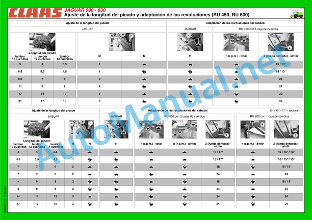
6.1.26 Adjust the chopping length
6.1.27 Assemble the bottom plate
6.1.28 Protective device under the chopper casing
6.2 Corn Cracker
6.2.2 Roller distance indicator
6.2.3 Program the distance of the Corn-Cracker
6.2.4 Basic adjustment of the Cracker rollers
6.2.5 Manually adjust the distance of the rollers
6.2.6 Dismantling the Corn-Cracker
6.2.7 Fix the Corn-Cracker
6.2.8 Placement of the intermediate piece of the discharge channel
6.2.9 Assemble the intermediate piece of the discharge channel for grass harvesting
6.2.10 Lift the Corn-Cracker from the machine
6.2.11 Assemble the Corn-Cracker
6.2.12 Placement of the intermediate piece of the discharge channel
6.3 Corn-cracker HD
6.3.2 Roller distance indicator
6.3.3 Programming the distance of the Corn-Cracker (electrical crack regulation)
6.3.4 Basic adjustment of the Cracker rollers
6.3.5 Dismantling the Corn-Cracker
6.3.6 Adjust the Cracker HD rollers
6.3.7 Assemble the Corn-Cracker
6.4 Auto-Contour
6.4.1 Reversing valve for the heads
6.4.2 Adjust the head lowering speed
6.4.3 Differences between the two systems
6.4.4 Commissioning the Auto-Contour, Contour, Contour-Plus systems and cutting height preselection
6.4.5 Operation with the Auto-Contour system (cutting height regulation with transverse header leveling)
6.4.6 Operation with the Contour-Plus system (cutting height regulation)
6.4.7 Operation with the Contour system (support pressure regulation)
6.4.8 Cutting height preselection
6.4.9 Potentiometer for indicating cutting height
6.5 Commissioning the forage chopper
6.5.2 Connect the drive of the chopping devices
6.5.3 Disconnect the drive of the chopping devices
6.5.4 Reverse the direction of travel of the feeding devices
6.5.5 The feeding devices stop, the metal detector has located a magnetizable metal object
6.5.6 Raise the roller distributor
6.6 Power Housing
6.6.1 Disassemble the power supply casing
6.6.2 Assemble the power supply housing
6.6.3 Folding the power supply unit
6.6.4 Failure in the investment process
6.7 Incident and solution
6.7.1 Sharpening device
6.7.2 Control light function (17 – red)
6.7.3 Fault chart – automatic sharpening device
6.7.4 Test of sensors and potentiometers
6.8 Stone detector
6.8.1 Connect the stone detector
6.8.2 The feeding devices stop, the stone detector has located stones or similar foreign bodies
6.8.3 Disconnect the stone detector
6.9 ACTISILER
6.9.1 Fill the equipment with CLAAS ACTISILER silage additives (additional equipment)
6.9.2 Emptying the CLAAS ACTISILER silage additive equipment (additional equipment)
6.9.3 CLAAS ACTISILER silage additive equipment (additional equipment) overview of controls
6.9.4 Connecting CLAAS ACTISILER silage additive equipment (additional equipment)
6.9.5 Operating CLAAS ACTISILER silage additive equipment (additional equipment)
6.9.6 Adjust the calibration value of the CLAAS ACTISILER silage additive equipment (additional equipment)
6.9.7 Disconnecting the CLAAS ACTISILER silage additive equipment (additional equipment)
6.9.8 CLAAS ACTISILER faults and solutions
7 Maintenance – base machine
7.1 Important maintenance instructions
7.1.1 Important maintenance instructions and safety regulations
7.1.2 Chains
7.1.3 Straps
7.1.4 Screws
7.1.5 Imbalance
7.1.6 Lubrication
7.1.7 Brakes
7.1.8 Wheels / tires
7.1.9 Machines with electrical regulation of the bedknife
7.1.10 Hydraulic system
7.1.11 Electrical installation
7.1.12 Welding work
7.1.13 Air conditioning installation
7.1.14 Protective devices / spare parts
7.1.15 Metal detector, metal detected
7.1.16 Chopper drum
7.1.17 Machine on supports
7.2 Maintenance and lubricant tables
7.2.1 Base machine maintenance table
7.3 Turn off the machine and secure it
7.3.1 Turn off the machine and secure it
7.4 Eliminate a fault in the flow
7.4.1 Eliminate the flow fault
7.5 Lubricant tables
7.5.1 Lubricants
7.5.2 Consider the timing gear lubricant
7.5.3 Take into account the input of the air conditioning equipment
7.6 Hydraulic installation
7.6.2 Pressure accumulator
7.6.3 Check the hydraulic oil level
7.6.4 Change hydraulic oil
7.6.5 Change the hydraulic pump oil filter
7.6.6 Change the return filter
7.6.7 Filling prescription for hydraulic oil change
7.6.8 Adjust the hydraulic pump
7.6.9 Foot brake and brake fluid
7.7 Gears
7.7.2 Gearbox
7.7.3 Reducers
7.7.4 Distribution gear
7.7.5 Gear for upper rollers
7.7.6 Gear for track rollers
7.7.7 Gearbox and reversing
7.7.8 Spur gear for upper rollers
7.7.9 CARRARO drive steering axle – differential gear
7.7.10 CARRARO drive steering axle – steering axle gear
7.7.11 CARRARO drive steering axle – steering axle drive
7.7.12 Fan gear (motor)
7.8 Chop
7.8.1 Download Accelerator
7.8.2 Reset the throttle paddle wheel
7.8.3 Clean and preserve the Corn-Cracker
7.8.4 Grease the Corn-Cracker
7.8.5 Check the Corn-Cracker rollers
7.8.6 Corn-Cracker Drive
7.8.7 Discharge elbow wear plates
7.8.8 Clean the discharge elbow
7.8.9 Adjusting the smooth transport roller separator rail
7.8.10 Adjust the drive for feeding
7.8.11 Check the operation of the inertia indicator
7.8.12 Tension the tension springs for the pre-pressing and pressing roller
7.8.13 Adjust the discharge elbow lock
7.8.14 Adjusting the elastic cylinder for the main drive
7.9 Cabin
7.9.1 Put the air conditioning equipment into operation
7.9.2 Clean the cabin filter
7.9.3 Clean the condenser
7.9.4 Check coolant level
7.9.5 Renew the filter dryer
7.9.6 Refrigerant filling quantity – refrigerant R 134 a
7.9.7 Compressor oil
7.9.8 Maintenance work before harvest
7.10 Fire extinguisher
7.10.1 Check the fire extinguisher
7.11 Left drive belts
7.11.1 Remove the main drive belt (1)
7.11.2 Install the main drive belt (1) and adjust it
7.12 Right drive belts
7.12.1 Remove the fan drive belt (10) (up to machine number…)
7.12.2 Position and adjust the fan drive belt (10) (up to machine number…)
7.12.3 Remove the fan drive belt (10) (from machine number…)
7.12.4 Position and adjust the fan drive belt (10) (from machine number…)
7.12.5 Remove the Corn-Cracker drive belt (11)
7.12.6 Position and adjust the Corn-Cracker drive belt (11)
7.12.7 Remove the feed drive belt (12)
7.12.8 Install and adjust the feed drive belt (12)
7.13 Pressurized air cleaning equipment
7.13.1 Pressurized air cleaning equipment
7.13.2 Compressed air connection points
7.13.3 Take into account when taking in air (JAGUAR 900 – 830 Speedstar)
7.13.4 Empty the water from the compressed air tank
7.13.5 Pressure regulator
7.13.6 Check the safety valve
7.14 Trailer air brake equipment
7.14.1 Installation of air brakes
7.14.2 Empty the water from the compressed air tank
7.14.3 Pressure regulator
7.14.4 Check the safety valve
7.14.5 Air pressure brake system inspection indication
7.15 Silage Additive Equipment
7.15.1 Clean the silage additive equipment nozzle
7.15.2 Clean the equipment filter for silage additives
7.15.3 Clean silage additive equipment
7.15.4 Prepare silage additive equipment for wintering
7.15.5 Setup of CLAAS ACTISILER silage additive equipment (additional equipment)
7.15.6 Sweeping CLAAS ACTISILER silage additive equipment (additional equipment)
7.16 Hibernation
7.16.1 Recommendations for the conservation of the forage harvester during the winter
8 Centralized lubrication
8.1 Management of the central lubrication system
8.1.1 Function of the central lubrication system (additional equipment)
8.1.2 Central lubrication system with 8 liter grease tank and electronic pressure switch
8.1.3 Vacuum indication
8.1.4 Fill the lubricating grease container
8.1.5 Allowed types of grease
8.1.6 Scope of a fill
8.1.7 Manually put the central lubrication system into operation
8.1.8 Filling with the filling pump
8.1.9 Filling with filling pumps, 25/50 kg container
8.1.10 Filling using a quick fill connection
8.1.11 Manually lubricate the machine
8.1.12 Operation without Corn-Cracker
8.1.13 Operation with head without central lubrication system
8.2 Renew the grease pipes
8.2.2 Mount the grease pipes on the machine side
8.2.3 Central lubrication system diagram
8.3 Incident and solution
8.3.1 Central lubrication system
9 Maintenance – engine
9.1 Important maintenance instructions
9.1.1 Important maintenance instructions and safety regulations
9.1.2 Cooling water hoses and air intake hoses
9.1.3 Coolant liquid
9.1.4 Straps
9.1.5 Clean engine space and danger areas
9.2 Maintenance and lubricant tables
9.2.1 Engine maintenance table
9.2.2 Engine lubricant table
9.2.3 Cooling system lubricant table
9.3 Turn off the machine and secure it
9.3.1 Turn off the machine and secure it
9.4 Engine summary
9.4.1 Overview of Mercedes-Benz OM 502 LA engines (up to machine no. …)
9.4.2 Overview of Mercedes-Benz OM 457 LA engines (up to machine no. …)
9.4.3 Overview of Mercedes-Benz OM 502 LA engines (from machine no. …)
9.4.4 Overview of Mercedes-Benz OM 460 LA engines (from machine no. …)
9.5 Injection / fuel system
9.5.2 Fuel installation
9.5.3 Fuel tank
9.5.4 Manual fuel feed pump with fuel prefilter
9.5.5 Fuel filter (up to machine number…)
9.5.6 Fuel filter (from machine number…)
9.5.7 Water collector / fuel pre-filter (standard equipment)
9.5.8 Water collector / fuel prefilter (additional equipment)
9.5.9 Bleeding the fuel system
9.5.10 Check the engine oil level
9.5.11 Engine oil change
9.5.12 Drain the old oil
9.5.13 Oil filter
9.5.14 Change the diesel engine purge filter (up to machine no. …)
9.5.15 Top up engine oil
9.5.16 Adjusting the elastic cylinder of the fan drive
9.6 Cooling system
9.6.1 Coolant liquid
9.6.2 Identify the type of refrigerant
9.6.3 Fill cooling agent
9.6.4 Change the coolant
9.6.5 Mixing ratio of cooling agent
9.6.6 Engine block water drain screws
9.6.7 Drain the coolant from the water radiator
9.6.8 Fill the water radiator coolant
9.6.9 Excess pressure
9.6.10 Antifreeze / Anticorrosive
9.6.11 Danger warning sign
9.6.12 Coolant temperature
9.6.13 Shut down the overheated engine
9.6.14 Diesel engine failure
9.6.15 Radiator protection
9.6.16 Clean the water cooler, oil cooler and charge air cooler
9.6.17 Check the cleaning rotor cooling assembly
9.7 Air filter
9.7.1 Air filter
9.7.2 Warning device
9.7.3 Clean the air filter suction screen
9.7.4 Clean the air filter (up to machine number…)
9.7.5 Clean the air filter (from machine number…)
9.7.6 Safety cartridge (up to machine no. …)
9.7.7 Security cartridge (from machine number…)
9.8 Electrical/electronic installation
9.8.1 Battery
9.8.2 Three-phase generator
9.9 Incident and solution
9.9.1 Engine
9.10 Hibernation
9.10.1 Winter maintenance tips for engines
10 Greasing scheme
10.1 Grease points
10.1.1 General warnings
10.1.2 Lubricants
10.1.3 Greasing intervals
10.1.4 Grease poi
John Deere Repair Technical Manual PDF
John Deere Repair Technical Manual PDF
John Deere Repair Technical Manual PDF
John Deere Diesel Engines POWERTECH 2.9 L Component Technical Manual CTM126 Spanish
John Deere Repair Technical Manual PDF
John Deere Repair Technical Manual PDF
John Deere Transmission Control Unit Component Technical Manual CTM157 15JUL05
John Deere Repair Technical Manual PDF
John Deere Parts Catalog PDF
John Deere Tractors 7500 Parts Catalog CPCQ26568 30 Jan 02 Portuguese
John Deere Repair Technical Manual PDF
John Deere Repair Technical Manual PDF
John Deere Repair Technical Manual PDF

