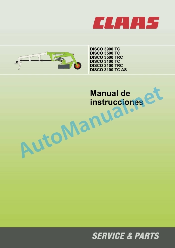
Claas Disco 3100 Tc (F51) Mower Operator Manual ES
$50.00
- Model: Disco 3100 Tc (F51) Mower
- Type Of Manual: Operator Manual
- Language: ES
- Format: PDF(s)
- Size: 7.8 MB
File List:
00 0290 338 2.pdf
00 0290 338 2.pdf:
1 Machine overview
1.1 DISC 3900 TC; 3500 TC/CRT; 3100 TC/CRT
1.1.1 Denominations
1.2 DISC 3100 TC AS
1.2.1 Denominations
2 Introduction
2.1 General instructions
2.1.1 Handling of the manual
Texts and figures
Structuring with the structure of constructive groups
Search and find
Technical instructions
Direction signs
2.1.2 Validity of the manual
2.2 Identification plates and identification numbers
2.2.1 Spare parts and technical issues
2.2.2 Identification plate
3 Security
3.1 General safety instructions
3.1.1 General safety information
3.1.2 Proper use of the machine
3.1.3 Predictably foolish misuse
3.1.4 Regulations, laws and standards
3.1.5 Technical status
3.1.6 Operational security
3.1.7 Hydraulic installation
3.1.8 Safety devices on the machine
3.1.9 Conduct in dangerous situations and in the event of accidents
3.1.10 Decommissioning and waste disposal
3.2 Warning and danger instructions
3.2.1 Indication
3.3 Graphic danger symbols
3.3.1 General information on warning symbols
3.3.2 Position on the machine
00 0515 130 0 (2)
00 0515 134 0 (33)
00 0480 462 0 (1)
00 0514 899 0 (8)
00 0515 380 0 (21)
00 0516 039 0 (22)
00 0515 139 1 (50)
00 0514 799 0 (6)
00 0516 038 0 (21)
00 0516 052 0 (25)
00 0514 825 0 (32)
4 Technical data
4.1 DISC 3900 TC – type F53
4.1.1 Measurements and weight
4.1.2 Requirements for the tractor
4.1.3 Model
4.1.4 Tires
4.1.5 Acoustic intensity level
A- equivalent calculated constant acoustic intensity level
Measurement procedure
4.2 DISC 3500 TC / DISC 3500 TRC – type F52
4.2.1 Measurements and weight
4.2.2 Requirements for the tractor
4.2.3 Model
4.2.4 Tires
4.2.5 Acoustic intensity level
A- equivalent calculated constant acoustic intensity level
Measurement procedure
4.3 DISC 3100 TC / DISC 3100 TRC – type F51
4.3.1 Measurements and weight
4.3.2 Requirements for the tractor
4.3.3 Model
4.3.4 Tires
4.3.5 Acoustic intensity level
A- equivalent calculated constant acoustic intensity level
Measurement procedure
4.4 DISC 3100 TC AS – type F51
4.4.1 Measurements and weight
4.4.2 Requirements for the tractor
4.4.3 Model
4.4.4 Tires
4.4.5 Acoustic intensity level
A- equivalent calculated constant acoustic intensity level
Measurement procedure
5 Before first start-up
5.1 General instructions
5.1.1 Checklist for first start-up
5.2 Adaptation to the machine
5.2.1 Cardan shaft – check the length
Cardan shaft – shortest operating position
Cardan shaft – longest operating position
5.2.2 Cardan shaft – adapt the length
Cardan shaft without sealing ring in the outer profile tube
Cardan shaft with sealing ring on the outer profile tube
5.2.3 Mount the cardan shaft to the machine
Sliding bolt – closure
Close shot
QS Closure
5.2.4 Adapt lateral displacement
Adjust the length of the hydraulic cylinder
Hydraulic cylinder lock position
5.3 Additional equipment
5.3.1 Wide spreading device (G03 0010)
DISC 3900 TC
DISC 3500 TC
DISC 3100 TC
5.3.2 Extension of the swath plates (G03 0060)
DISC 3900 TC
5.3.3 High cut skids (B03 0020)
5.3.4 Plug-in skids (C03 0030)
DISC 3900 TC
DISC 3500 TC/TRC
DISC 3100 TC / TRC / TC AS
5.3.5 Hydraulic connection for tractor (R03 0030)
6 Before each start-up
6.1 General instructions
6.1.1 Commissioning checklist
7 Assemble/disassemble the machine
7.1 Assemble the machine
7.1.1 General instructions
7.1.2 Attach the hitch bracket
7.1.3 Place the support leg upwards
7.1.4 Mount the cardan shaft
QS Closure
Synchronized wide angle joint
7.1.5 Connect the hydraulic pipes
Hydraulic pipes – lifting
Hydraulic hoses – turn
Hydraulic pipe – discharge
Hydraulic hose – transverse conveyor belt
7.1.6 Plug in the power supply
7.1.7 Transverse conveyor belt control piece
7.2 Dismantle the machine
7.2.1 General instructions
7.2.2 Remove the support leg
7.2.3 Unplug the power supply
7.2.4 Transverse conveyor belt control piece
7.2.5 Uncouple the hydraulic pipes
Hydraulic pipe – discharge
Hydraulic hoses – turn
Hydraulic pipes – lifting
Hydraulic hose – transverse conveyor belt
7.2.6 Dismantle the cardan shaft
Sliding bolt – closure
Close shot
QS Closure
7.2.7 Unhooking the coupling bracket
8 Driving and transportation
8.1 General instructions
8.1.1 Road traffic
Machine marking for road traffic
8.1.2 Journey through the countryside
8.1.3 Driving characteristics
8.2 Transport position
8.2.1 Folding protective devices
8.2.2 Raise the mower
8.2.3 Place in transport position
8.2.4 Lower the transverse conveyor belt into the working and transport position
8.3 Load the machine for transport
8.3.1 Load/unload the machine
9 Setting for field work
9.1 Working position
9.1.1 Folding protective devices
9.1.2 Adjust the hitch brackets
9.1.3 Adjust cutter bar discharge
9.1.4 Adjust cutting height
9.2 DISCO 3900 TC / 3500 TC / 3100 TC / TC AS conditioner
9.2.1 Conditioner speed
DISC 3900 TC:
DISC 3500 TC / 3100 TC / 3100 TC AS:
9.2.2 Diverter stop
9.2.3 Windrower plates
9.2.4 Wide spreading device
9.3 DISCO 3500 TRC / 3100 TRC Conditioner
9.3.1 Windrower plates
9.3.2 Mow without conditioning effect
9.4 DISCO 3100 TC AS transverse conveyor belt
9.4.1 Adjust the discharge cap
9.4.2 Cross conveyor belt – adjust the ejection width
10 Use at work
10.1 Field work in the field
10.1.1 General instructions
10.1.2 Turn to working position
10.1.3 Lower the mower
10.2 Mow
10.2.1 Put the machine to work
10.2.2 Mowing technique
10.2.3 Position at the ends of the plot
10.2.4 Instructions on mowing
10.2.5 Difficult harvest conditions
10.2.6 Recommendation regarding environmental protection
10.3 Mowing with DISCO 3100 TC AS transverse conveyor belt
10.3.1 Put the machine to work
10.3.2 Raise/lower the transverse conveyor belt
10.3.3 Connecting/disconnecting the cross conveyor belt
10.3.4 Mowing technique
11 Maintenance
11.1 General warning instructions
11.1.1 Screws
11.1.2 Lubrication
11.1.3 Wheels / tires
11.1.4 Hydraulic system
11.1.5 Electrical equipment
11.1.6 Protection devices
11.1.7 Spare parts
11.1.8 Imbalance
11.1.9 Cleaning and care
11.1.10 Conservation proposals during winter
11.2 Maintenance chart
11.2.1 Maintenance intervals
11.3 Lubricants
11.3.1 Lubricant table
11.4 Gear / clutch / cardan shaft
11.4.1 Main gear
gear down
Clean the purge valves
Check the oil level
Fill oil
Drain/change oil
11.4.2 Distributor gear
gear down
Clean the purge valves
Check the oil level
Fill oil
Drain/change oil
11.4.3 Bevel gear
Check the oil level
Fill oil
Drain/change oil
Clean the purge valve
11.4.4 Maintenance of cardan shafts
General information regarding cardan shafts
11.4.5 Friction clutch
11.4.6 Ventilate the friction clutch
11.4.7 Renew the friction discs
11.5 Chassis
11.5.1 Wheels and tires
11.5.2 Changing wheels
11.6 Hooking device
11.6.1 Adjust the pressure springs of the hitch brackets
11.7 Hydraulic installation
11.7.1 Hydraulic equipment
11.7.2 Hydraulic pipes
11.7.3 Pressure retainer
Check pretension pressure
11.7.4 Tension the hydraulic pump drive belt
11.7.5 Change the hydraulic pump drive belt
11.7.6 Cross conveyor hydraulic oil
Check the oil level
Fill oil
Drain/change oil
11.8 Harvesting device
11.8.1 Cutter bar gear
Check the oil level
Fill oil
Drain/change oil
11.8.2 Mower blade box
11.8.3 Change the blades
Quick blade change system
11.8.4 Blade support
11.8.5 Maintenance of mower discs
Clean the drain hole
Check wear strips
11.8.6 Change the mower discs
11.8.7 Assembling the bevel pinion units
11.8.8 Adjust the protection device
Protective canvas support, front
Left/right protective breastplate support
11.8.9 Winding protection
11.9 Forage preparation
11.9.1 Tension the conditioner drive belt
11.9.2 Change the conditioner drive belt
11.9.3 Assembling/disassembling DISCO 3900 TC / 3500 TC / 3100 TC conditioner tines
11.9.4 DISCO 3500 TRC / 3100 TRC conditioner rollers
Adjust the draft springs
Adjust synchronized gear
Adjust the distance between rollers
11.10 Harvest placement
11.10.1 Adjust the cross conveyor belt
11.11 Mounting parts/machine body
11.11.1 Adjust the oscillating frame pull springs
11.12 Errors and solution
12 Grease plane
12.1 Grease points
12.1.1 Lubricants
12.1.2 Greasing intervals
12.1.3 Greasing points – 8 h
12.1.4 Greasing points – 20 h
12.1.5 Greasing points – 100 h
12.1.6 Grease points – 250 h
Alphabetical index
John Deere Repair Technical Manual PDF
John Deere Repair Technical Manual PDF
John Deere DF Series 150 and 250 Transmissions (ANALOG) Component Technical Manual CTM147 05JUN98
John Deere Repair Technical Manual PDF
John Deere Repair Technical Manual PDF
John Deere Repair Technical Manual PDF
John Deere Application List Component Technical Manual CTM106819 24AUG20
John Deere Repair Technical Manual PDF
John Deere Parts Catalog PDF
John Deere Tractors 6300, 6500, and 6600 Parts Catalog CQ26564 (29SET05) Portuguese
John Deere Repair Technical Manual PDF
John Deere PowerTech M 10.5 L and 12.5 L Diesel Engines COMPONENT TECHNICAL MANUAL CTM100 10MAY11
John Deere Repair Technical Manual PDF
John Deere POWERTECH E 4.5 and 6.8 L Diesel Engines TECHNICAL MANUAL 25JAN08
John Deere Repair Technical Manual PDF
John Deere 18-Speed PST Repair Manual Component Technical Manual CTM168 10DEC07


