Claas Dominator 130 68 S (156) Combines Operator Manual FR
$50.00
- Model: Dominator 130 68 S (156) Combines
- Type Of Manual: Operator Manual
- Language: FR
- Format: PDF(s)
- Size: 18.9 MB
File List:
00 0293 211 2.pdf
00 0294 841 0.pdf
00 0293 211 2.pdf:
Contents
1 Introduction
1.1 General advice
1.1.1 Use of the instructions
1.1.2 Validity of the notice
1.1.3 Technical information
1.1.4 Driving on the road
1.1.5 Advice regarding electronic engine management
1.2 Attached parts / machine casing
1.2.1 Spare parts and technical questions
1.2.2 Machine nameplate
1.2.3 CATERPILLAR 3056 E engine nameplate
1.2.4 PERKINS 1006-6T motor nameplate
1.2.5 CATERPILLAR C6.6 engine nameplate
1.2.6 Drive axle nameplate
1.2.7 Steering axle nameplate
1.2.8 Hitch clevis nameplate
1.2.9 Hitch frame nameplate
1.2.10 Cabin nameplate
1.2.11 Straw chopper nameplate
2 Overview
2.1 Assembled parts / Machine casing
2.1.1 Machine overview
2.1.2 Access to the driving position and maintenance points
3 Security
3.1 General advice
3.1.1 General advice
3.1.2 Important
3.1.3 Use in accordance with instructions
3.1.4 Clearly non-compliant use
3.1.5 Safety and accident prevention instructions
3.1.6 Safety and accident prevention instructions for the combine harvester
3.1.7 Before commissioning – General
3.1.8 Additional weights
3.1.9 Transport of people
3.1.10 General rule of conduct
3.1.11 Moving the combine harvester on the road
3.1.12 Driving on a slope
3.1.13 Exit the machine
3.1.14 Front implements and trailers
3.1.15 Deposit of harvested product / deposition of straw
3.1.16 Grain recovery
3.1.17 Air conditioning
3.1.18 Adjustment and maintenance work
3.1.19 Pressure accumulator
3.1.20 Antifreeze
3.1.21 First aid measures
3.1.22 Decommissioning and disposal
3.1.23 Place the safety support in the supply channel
3.1.24 Remove the safety support from the supply channel
3.1.25 Block the machine with blocks to avoid any risk of movement
3.1.26 Raise and attach the straw guide cloth
3.1.27 Lifting the machine using jacks
3.1.28 Fire extinguisher
3.1.29 Battery cut-off switch
3.1.30 Hydraulic fluid poses a risk of injury
3.1.31 Load the machine and secure it
3.1.32 Unscrew the crane eyes.
3.2 Safety information
3.2.1 Marking of warnings and dangers
3.3 Warning pictograms
3.3.1 General instructions regarding warning pictograms
3.3.2 Motor
3.3.3 Chassis
3.3.4 Cabin / driving position
3.3.5 Power group
3.3.6 Threshing bodies
3.3.7 Separation
3.3.8 Deposit of harvested product / deposit of straw
3.3.9 Grain recovery
3.3.10 Attached parts / machine casing
3.4 Safety sticker
3.4.1 General instructions regarding safety stickers
3.4.2 Chassis
4 Technical characteristics
4.1 DOMINATOR 150 / 140 / 130
4.1.1 General advice
4.1.2 CATERPILLAR C6.6 engine
4.1.3 CATERPILLAR 3056E engine
4.1.4 Perkins 1006-T6 engine
4.1.5 Chassis
4.1.6 Chassis tire pressure
4.1.7 Chassis, track
4.1.8 Brake
4.1.9 Management
4.1.10 Electrical/electronic system
4.1.11 Cabin / driving position
4.1.12 Power supply organs
4.1.13 Threshing bodies
4.1.14 Separation
4.1.15 Cleaning
4.1.16 Grain recovery
4.1.17 Dimensions of assembly parts / machine casing
4.1.18 Weight of assembly parts / machine casing
5 Before first commissioning
5.1 General advice
5.1.1 General warnings Before initial commissioning
5.1.2 Checklist for initial commissioning
5.2 Axle frame
5.2.1 Remove/install the wheels
5.2.2 Overview of the steering axle
5.2.3 Adjust the steering axle from road position to working position
5.2.4 Steering axle 00 0649 950 1 – adjust track
5.3 Coupling device
5.3.1 Install the hitch yoke (optional equipment)
5.4 Electrical system / electronic system
5.4.1 Install the fan/air conditioning fuse
5.5 Power unit
5.5.1 Install / adjust the support plates
5.5.2 Align the receiving posts
5.5.3 Check the front tool cylinders
5.5.4 Check the front attachment suspension springs
5.6 Grain recovery
5.6.1 Close the hopper drain tube cleaning hatch.
5.6.2 Install the hopper protection device
6 Before each commissioning
6.1 General advice
6.1.1 General warnings Before each commissioning
6.1.2 Checklist for daily start-up
7 Overview of control elements
7.1 General advice
7.1.1 General warnings overview of control elements
7.2 Cabin / driving position
7.2.1 Overview of the driving position (DOMINATOR 130)
7.2.2 Overview of the driving position (DOMINATOR 150/140)
7.2.3 Hydraulic distributor (DOMINATOR 130 hydraulic lifting system)
7.2.4 Multifunction lever (DOMINATOR 150 / 140)
7.2.5 Control console (DOMINATOR 130)
7.2.6 Diesel engine speed selector (DOMINATOR 130, CATERPILLAR C-6.6, 3056 E)
7.2.7 Diesel engine speed lever (DOMINATOR 130, Perkins 1006-T6)
7.2.8 Function of indicator lights 7 and 8 (DOMINATOR 130)
7.2.9 Control console (DOMINATOR 150 / 140)
7.2.10 Diesel engine speed selector (DOMINATOR 150 / 140)
7.2.11 Functions of indicator lights 15 and 18 (DOMINATOR 150 / 140)
7.2.12 Overview of the steering column
7.2.13 Cab roof control elements
7.2.14 Cabin with fan
7.2.15 Cabin with air conditioning (with York compressor)
7.2.16 Cabin with air conditioning (with Sanden compressor)
7.2.17 Cabin with fan and heater
7.2.18 Control levers
7.2.19 Function monitoring device
7.3 Assembled parts / Machine casing
7.3.1 Work lights
7.3.2 Cabin
7.3.3 Sun roof
7.3.4 Toolbox
8 Mount/dismount the front tool
8.1 General advice
8.1.1 General warnings place/remove the front tool
8.2 Install the front tool
8.2.1 Hanging the front tool
8.2.2 Locking the front tool
8.2.3 Install the cardan shaft
8.2.4 Connect the hydraulic system
8.2.5 Connect the electrical circuit (additional equipment)
8.2.6 Remove the stands
8.3 Remove the front tool
8.3.1 Install the crutches
8.3.2 Disconnect the hydraulic system
8.3.3 Disconnect the electrical circuit (additional equipment)
8.3.4 Dismantle the cardan shaft
8.3.5 Unlock the front tool
8.3.6 Unhook the front tool
9 Road driving and transport
9.1 General advice
9.1.1 General safety instructions Travel and transport
9.1.2 Preparing for driving on the road
9.1.3 Preparing for driving in the field
9.2 Engine
9.2.1 Adjusting the diesel engine speed (DOMINATOR 150 / 140)
9.2.2 Starting the diesel engine (DOMINATOR 150 / 140)
9.2.3 Stopping the diesel engine (DOMINATOR 150 / 140)
9.2.4 Adjusting the speed of the diesel engine (DOMINATOR 130)
9.2.5 Starting the diesel engine (DOMINATOR 130)
9.2.6 Stopping the diesel engine (DOMINATOR 130)
9.3 Axle frame
9.3.1 Advance lever (DOMINATOR 150 / 140)
9.3.2 Shifting gears (DOMINATOR 150 / 140)
9.3.3 Advance lever (DOMINATOR 130)
9.3.4 Shifting gears (DOMINATOR 130)
9.3.5 Adjust the control resistance of the forward lever (DOMINATOR 150 / 140)
9.3.6 Driving characteristics
9.3.7 Towing the machine
9.3.8 Forward towing
9.3.9 Towing in reverse
9.4 Brake
9.4.1 Activate the parking brake
9.4.2 Release the parking brake
9.4.3 Foot brake
9.4.4 Braking / stopping the machine (DOMINATOR 150 / 140)
9.4.5 Brake / stop the machine (DOMINATOR 130)
9.4.6 Park the machine
9.5 Management
9.5.1 Management
9.5.2 Adjusting the steering column
9.6 Coupling device
9.6.1 Hitching the trailer
9.6.2 Unhitching the trailer
9.7 Cabin / driving position
9.7.1 Adjust the driver’s seat with mechanical suspension (standard model)
9.7.2 Adjust the driver’s seat with mechanical suspension (standard model)
9.7.3 Adjusting the mechanically cushioned driver’s seat (optional equipment)
9.8 Attached parts / machine casing
9.8.1 Pivoting the front ladder (standard)
9.8.2 Adjust the rear scale
10 Setting for work
10.1 General advice
10.1.1 General safety instructions, working settings
10.2 Power unit
10.2.1 Setting the cutting height display
10.2.2 Adjust the scraper profiles
10.2.3 Height adjustment of the feed chain
10.2.4 Adjust the lowering speed of the front implement (DOMINATOR 150)
10.3 Threshing bodies
10.3.1 Remove/install the concave segments (Multicrop concave)
10.3.2 Adjusting the concave basic setting
10.4 Separation
10.4.1 Adjust the separation flow control sensors
10.5 Cleaning
10.5.1 Check/adjust fan speed display
10.5.2 Adjust the cleaning flow control sensors
10.5.3 Remove the grids
10.5.4 Mount the grids
10.6 Deposit of harvested product / straw deposit
10.6.1 Remove the straw guide plate (straw chopper with standard distributor)
10.6.2 Install the straw guide plate (straw chopper with standard distributor)
10.6.3 Unscrew the articulated knives
10.6.4 Screw in the articulated knives
10.6.5 Straw chopper, grid mounting position
10.7 Grain recovery
10.7.1 Setting the DOMINATOR 150 hopper full indicator
11.1 General advice
11.1.1 General work warning advice
11.2 Structure and operation
11.2.1 Cutting deck
11.2.2 Threshing bodies
11.2.3 Shakers
11.2.4 Cleaning
11.2.5 Trimming
11.3 Basic rules for harvesting and combining
11.3.1 To be respected during harvesting and combining!
11.4 Front tool
11.4.1 Horizontal adjustment of the reel (mechanical)
11.4.2 Horizontal adjustment of the reel (hydraulic)
11.4.3 Adjust the reel peripheral speed
11.5 Power unit
11.5.1 Measure the ground support pressure
11.5.2 Raise the cutting height
11.5.3 Reverse front attachment / power unit
11.5.4 Switching on the front tool
11.5.5 Disconnect the front tool.
11.6 Threshing bodies
11.6.1 Clutching the threshers
11.6.2 Disconnect the threshing elements
11.6.3 Adjusting the concave
11.6.4 Installing/removing the deburring bats (additional equipment)
11.6.5 Eliminate windings on the beater
11.6.6 Adjust the mixer speed
11.6.7 Reduction of mixer speed (chain drive)
11.7 Separation
11.7.1 Adjusting the anti-splash fabric
11.7.2 Pay attention to straw jam alarms behind the separation
11.7.3 Set separation flow control display
11.7.4 Install/remove the sawtooth separators
11.8 Cleaning
11.8.1 Adjust fan speed
11.8.2 Adjust the ventilation hatch
11.8.3 Manually adjust the grids
11.8.4 Adjust the cleaning flow control display
11.9 Deposit of harvested product / straw deposit
11.9.1 Commissioning the straw chopper (swivel the standard distributor to the crushing position)
11.9.2 Stopping the straw chopper (pivot the standard distributor to the windrowing position)
11.9.3 Swivel the standard spreader into transport position, transport trailer
11.9.4 Adjust the counter-knives (standard straw chopper)
11.10 Grain recovery
11.10.1 Controlling the return of harvest
11.10.2 Open/close the hopper cover
11.10.3 Swivel the hopper discharge tube outwards / inwards (DOMINATOR 150 / 140)
11.10.4 Swivel the hopper discharge tube outwards/inwards (DOMINATOR 130)
11.10.5 Connect/disconnect hopper drain
11.10.6 Remove/install the hopper auger cover plates
11.10.7 Clean the machine to change crops
11.11 Grid tables / Threshing tables
11.11.1 Grid table
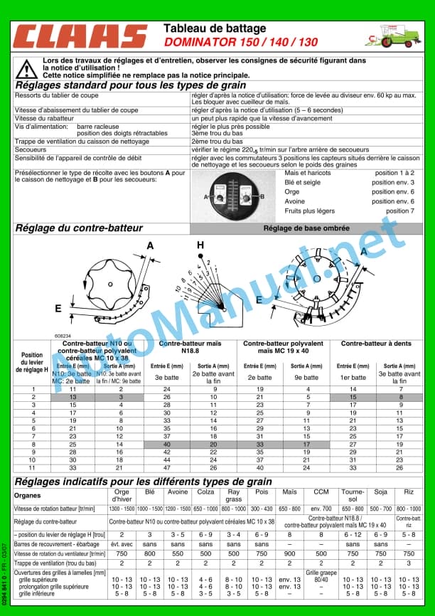
11.11.2 Threshing table
11.12 Trimming
11.12.1 Trimming bars
12 Incidents and remedy
12.1 General advice
12.1.1 General warning advice Fault and solution
12.2 Cabin / driving position
12.2.1 Power plant
12.2.2 Air conditioning incidents and remedies
12.3 Front tool
12.3.1 Front tool
12.4 Power supply unit
12.4.1 Failure and solution at the power supply unit
12.5 Threshing bodies
12.5.1 Failure and solution at the level of the threshing body
12.5.2 Drummer
12.6 Separation
12.6.1 Separation, failure and solution
12.7 Cleaning
12.7.1 Cleaning, failure and solution
12.8 Deposit of harvested product / deposition of straw
12.8.1 Harvest deposit / Straw deposit, failure and solution
12.9 Grain recovery
12.9.1 Grain recovery, failure and solution
12.9.2 Installing the hopper drain shear bolt
13 Maintenance
13.1 General advice
13.1.1 General warning advice Maintenance
13.2 General advice
13.2.1 Front tool
13.2.2 Clean the engine compartment and hazardous areas
13.2.3 Belts
13.2.4 Drives
13.2.5 Bolting
13.2.6 Lubrication
13.2.7 Cleanliness of lubricants
13.2.8 Brakes
13.2.9 Wheels / tires
13.2.10 Hydraulic system
13.2.11 Electrical system
13.2.12 Air conditioning
13.2.13 Protective devices
13.2.14 Spare parts
13.2.15 Unbalance
13.2.16 Welding work on the combine harvester
13.2.17 Turn off the machine
13.2.18 Cleaning bonded surfaces
13.2.19 Winterizing tips for combine harvesters
13.2.20 Coolant
13.3 Maintenance table
13.3.1 Maintenance frequencies
13.4 Lubricant table
13.4.1 Lubricants
13.5 Engine
13.5.1 Overview of the CATERPILLAR C-6.6 engine
13.5.2 Overview of the CATERPILLAR 3056 E engine
13.5.3 Overview of the PERKINS 1006-6T engine
13.5.4 Overview of the cooling elements
13.5.5 Clean the area surrounding the diesel engine
13.5.6 Drain fuel from fuel tank
13.5.7 Refueling the machine
13.5.8 Clean the fuel filler strainer
13.5.9 Close / open the fuel circuit shut-off valve
13.5.10 Bleeding air from the fuel system
13.5.11 Clean the fuel filter element
13.5.12 Drain the condensation water from the fuel pre-filter (standard equipment)
13.5.13 Replace the fuel pre-filter (standard equipment)
13.5.14 Drain the condensation water from the fuel pre-filter (additional equipment)
13.5.15 Replace the fuel pre-filter (additional equipment)
13.5.16 Replace fuel filter CATERPILLAR C-6.6 / 3056 E
13.5.17 Replace the PERKINS 1006-6T fuel filter
13.5.18 Check diesel engine oil level
13.5.19 Replace diesel engine oil/oil filter
13.5.20 Adjusting the diesel engine valves
13.5.21 Check the coolant level of the water cooler
13.5.22 Check the dosage of the coolant mixture
13.5.23 Drain the coolant from the radiator
13.5.24 Drain the liquid from the water cooler
13.5.25 Filling the cooler with coolant
13.5.26 Clean the radiator screen
13.5.27 Cleaning the cooling element
13.5.28 Replace coolant hoses
13.5.29 Clean/replace air filter of diesel engine with plastic housing
13.5.30 Replace the safety cartridge of the air filter with plastic housing of the diesel engine
13.5.31 Cleaning the suction grille
13.5.32 Replace the air suction hoses
13.5.33 Tighten the air suction hose clamps
13.6 Axle frame
13.6.1 Wheels / tires
13.6.2 Check the tightening torque of the wheel nuts/wheel bolts.
13.6.3 Drive axle gearbox, clean surrounding area
13.6.4 Check the oil level of the DOMINATOR 150 / 140 axle gearbox
13.6.5 Drain the oil from the DOMINATOR 150 / 140 axle gearbox
13.6.6 Fill the axle box with DOMINATOR 150 / 140 oil
13.6.7 Check the oil level of the DOMINATOR 130 axle gearbox
13.6.8 Drain the oil from the DOMINATOR 130 axle gearbox
13.6.9 Fill the DOMINATOR 130 axle gearbox with oil
13.6.10 Check the oil level of the drive axle gearbox
13.6.11 Change the oil from the drive axle gearbox
13.6.12 Filling the drive axle gearbox
13.6.13 Adjust the DOMINATOR 130 chassis coupling
13.6.14 Adjust the DOMINATOR 130 bypass valve
13.7 Brake
13.7.1 Check/top up the brake fluid level
13.7.2 Adjusting the parking brake
13.7.3 Adjusting the foot brake
13.8 Drive belts / drive chains
13.8.1 General safety advice
13.8.2 Left side drive diagram DOMINATOR 150 / 140 / 130
13.8.3 Right side drive diagram DOMINATOR 150 / 140 / 130
13.8.4 Adjust the belt (R1)
13.8.5 Adjust the belt (R2)
13.8.6 Adjust the belt (R3)
13.8.7 Adjust the belt (R4)
13.8.8 Adjust the belt (R5)
13.8.9 Adjust the belt (R8)
13.8.10 Belt adjustment (R9)
13.8.11 Adjust the belt (R10).
13.8.12 Remove the belt (R7)
13.8.13 Fitting the belt (R7)
13.8.14 Adjust the belt (R12).
13.8.15 Adjust the belt (R13)
13.8.16 Remove the belt (R14)
13.8.17 Fitting the belt (R14)
13.8.18 Adjust the belt (R14)
13.8.19 Remove the belt (R42)
13.8.20 Install the belt (R42)
13.9 Hydraulics
13.9.1 Check the hydraulic system oil level
13.9.2 Hydraulic system, change oil / replace oil filter / air filter DOMINATOR 150 / 140
13.9.3 Hydraulic system, change oil / replace oil filter / air filter DOMINATOR 130
13.10 Electrical/electronic system
13.10.1 Checking the battery acidity level
13.11 Cabin / driving position
13.11.1 Clean/replace the cabin air filter
13.11.2 Clean the cabin forced air filter
13.11.3 Clean the groups in the cabin roof
13.11.4 Commissioning the air conditioning
13.11.5 Measures to protect the air conditioning during prolonged rest periods DOMINATOR 130 with York compressor
13.11.6 Checking the humidity saturation of the air conditioning refrigerant
13.11.7 Replace the refrigerant in the air conditioning
13.12 Power supply unit
13.12.1 Clean feed channel receipts
13.12.2 Adjusting the feed chains
13.12.3 Adjusting the power chain torque limiter
13.12.4 Check the friction plates on the feed channel
13.13 Threshing bodies
13.13.1 Clean the destoner tray
13.13.2 Clean the threshing bodies
13.14 Separation
13.14.1 Cleaning the shakers
13.14.2 Checking the anti-splash fabric
13.14.3 Clean the separation flow control sensor
13.15 Cleaning
13.15.1 Clean flow control sensor cleaning
13.15.2 Clean the fan
13.15.3 Setting the fan speed display
13.15.4 Cleaning stepped waterfalls
13.15.5 Clean the grills
13.16 Grain recovery
13.16.1 Adjusting the grain elevator chain
13.16.2 Adjusting the grain elevator chain
13.16.3 Clean the auger buckets
13.16.4 Clean the hopper
13.16.5 Adjust the transport position of the hopper discharge tube support
13.17 Attached parts / machine casing
13.17.1 Checking the fire extinguisher
14 Lubrication plan
14.1 Lubrication points
14.1.1 General warning tips lubrication scheme
14.1.2 Fats
14.1.3 Lubrication intervals
14.1.4 Lubrication points – 10 o’clock left side
14.1.5 Lubrication points – 10 o’clock right side
14.1.6 Lubrication points – 50 h left side
14.1.7 Lubrication points – 50 h right side
14.1.8 Lubrication points – 100 h left side
14.1.9 Lubrication points – 100 h right side
14.1.10 Lubrication points – 500 h left side
14.1.11 Lubrication points – 500 h right side
Alphabetical index
John Deere Repair Technical Manual PDF
John Deere Repair Technical Manual PDF
John Deere Repair Technical Manual PDF
John Deere Repair Technical Manual PDF
John Deere Repair Technical Manual PDF
John Deere 18-Speed PST Repair Manual Component Technical Manual CTM168 10DEC07
John Deere Repair Technical Manual PDF
John Deere 16, 18, 20 and 24HP Onan Engines Component Technical Manual CTM2 (19APR90)
John Deere Repair Technical Manual PDF
John Deere Repair Technical Manual PDF
John Deere Repair Technical Manual PDF
John Deere Application List Component Technical Manual CTM106819 24AUG20


